Around the beginning of October 2015 I’ve got an oportunity to go for a synthmeet to show my new SDSV modules. The problem was I got no PSU or a modular case. I had only a week to DIY something and started with very simple mini PSU project, based on Doepfers A-100 MNT. As I use mostly 8 HP width drum modules, I decided to pack as lot as 16 pin connectors as possible. The limitation was the maximum PCB size I owned, 160 x 100 mm (common eurocard size). Here is my story of Mini PSU (Power Supply Unit) for modular synth.
Schematic
First of all I wanted to keep it simple, small and safe, therefore I used PSU wall wart as a AC source. Design is based on two half-wave rectifiers and 7812/7912 voltage regulators pair to get +/-12 V. There are 7 standard 16-pin connectors, so you can power up to 7 modules. D1 and D2 are used as rectifiers, D3-D6 as a 7X12 protection (1N4007 will be also ok). C7-C10 are tantalum type capacitors, therefore be shure you solder them correctly. LED1/LED2 with resistors are used as indicators, also ensure some minimum current will be draw from each 7X12. Filtering capacitors C1 and C4 voltage rating should be 35 V*. (I believe the first version of PSU used 6 capacitors, C1-C3 for positive rail and C4-C6 for negative, but after some calulations and to save space I just left only C1 and C4, with increased capacity). The PSU should be used with 12 VAC, 1 A (or greater) wall wart, fused, if possible.
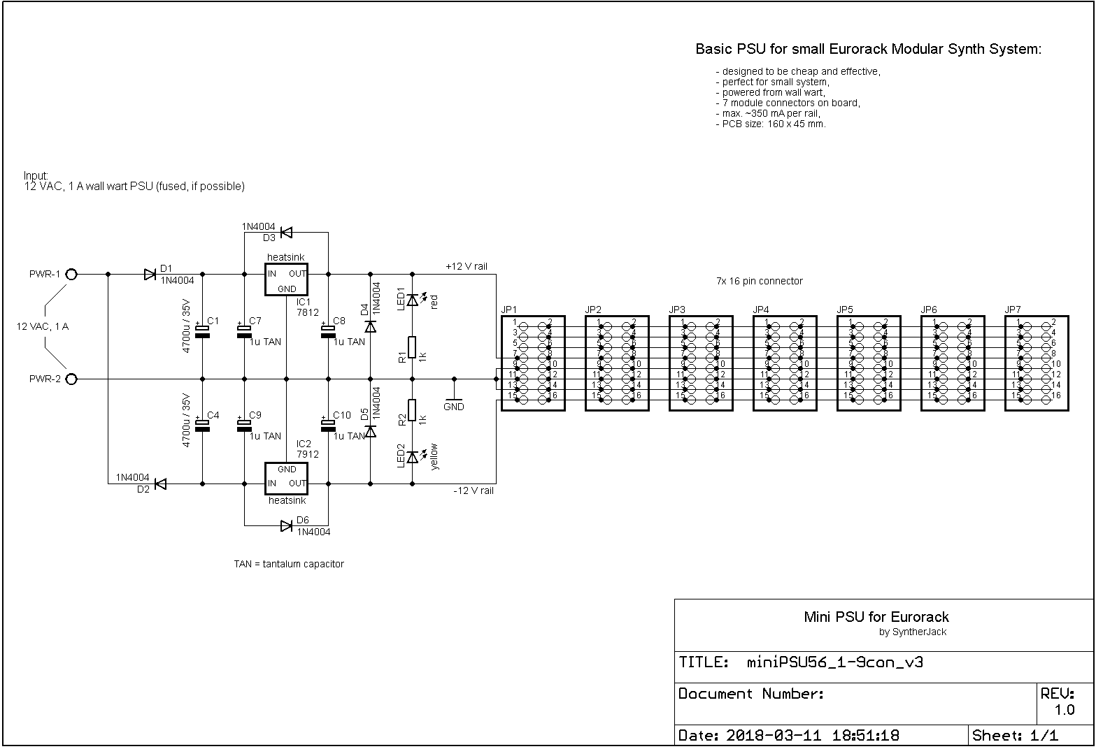
* ok, but why 35V? Output of the 12 VAC wall wart, as mentioned on the schematic, can go to around 15 VAC when PSU will be not loaded. As a result, 15 * 1,4 = 21 V peak (ommiting diode voltage drop) amplitude occurs at the capacitor input, with minimum 30% (some say 50%) margin of safety, just above 25 V. The next value over 25 V rating is 35 V. So, thats why.
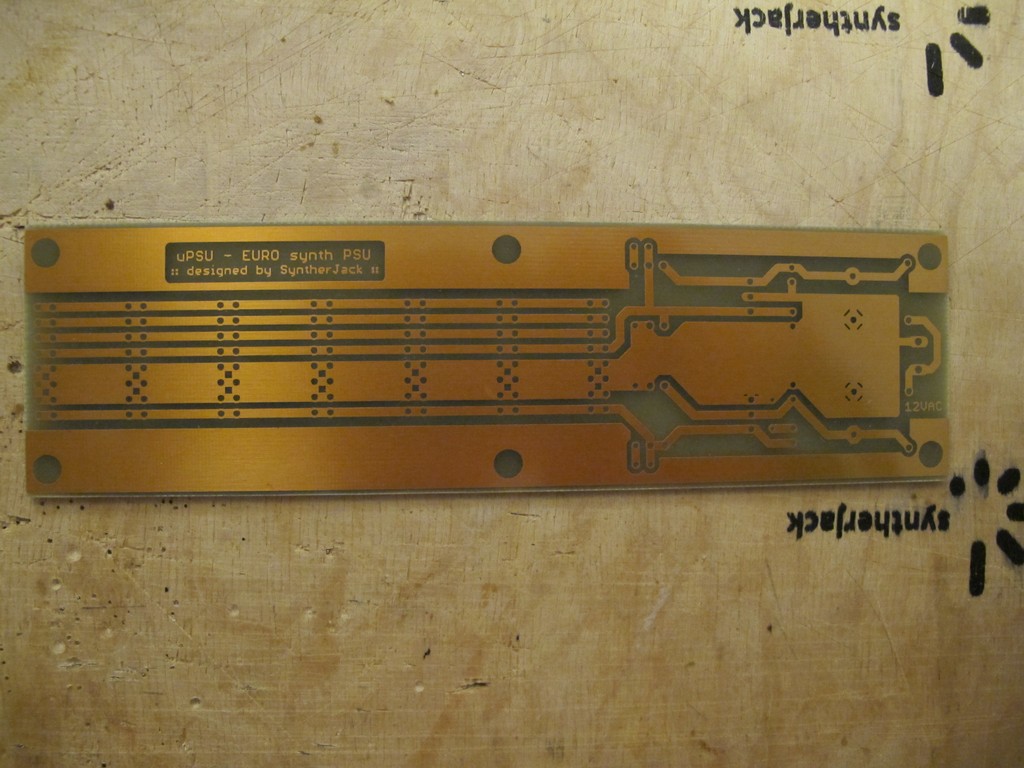
PCB design
There is not a lot to design for such simple circuit. PCB is one-sided and it has only one small jumper (near the C9 caption on the picture below). The main goal was to put as many 16 pin connectors as possible, leaving enough clearance between them. The heat sink is HS-115 type from Stonecold.
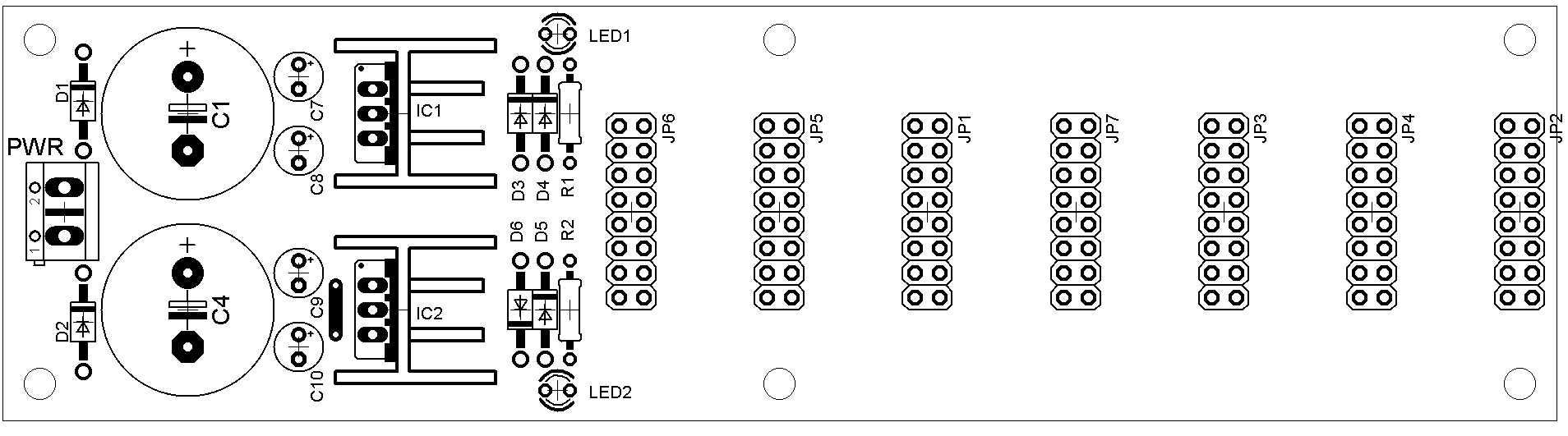
There are 6 screws holes to keep PCB in place inside your modular synth case. The middle ones are very important as they prevent PCB from bending as you put ribbon cables in the sockets. You can use standard eurorack IDC16 sockets if you like. I used cut double pin headers, because I’ve got a lot of them. Designed PCB size is 160 x 43 mm, but if you want to DIY, cut it to 160 x 45 mm.
Build
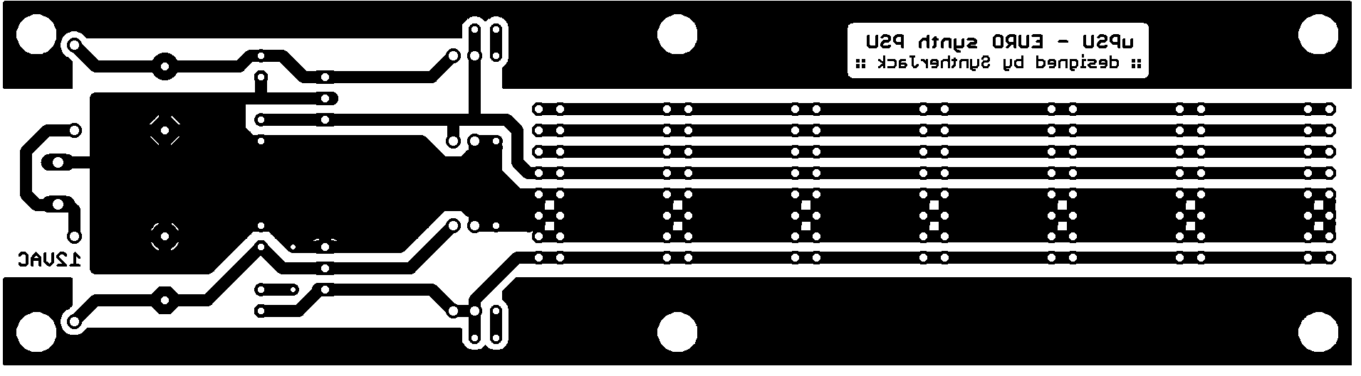
I had only few days to make it, so I went 100% DIY and etched PCB for myself. The only annoying part was drilling, way over 100 holes. You can find full PCB layers pack as attachment at the site bottom or HERE if you want to make one.
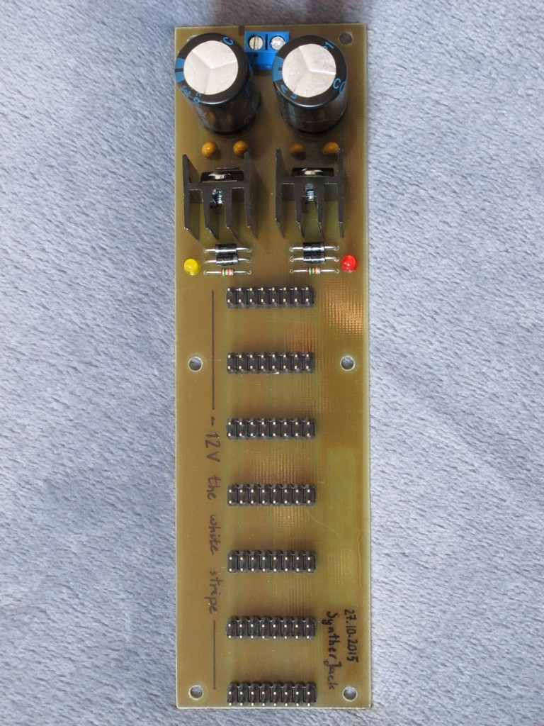
PSU integrated with busboard let you cut the price of the whole system (few euro, but still). I paid 3 euro for 1,2 A, 12 VAC wall wart (but you can find a cheaper one probably) and 6-7 euro for the rest of the parts. ~10 euro for the PSU is quite a good deal! If you have time for DIY of course. The build is very simple. The soldering itself took me around 1 hour. After you solder all the components and test your PSU put a protective coating on the copper layer, f.e. Contact Chemie Plastik 70 or similar. In addition you can mark where the RED STRIPE (not the white stripe) of the power supply ribbon cable goes.
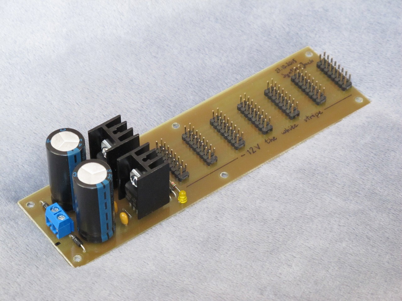
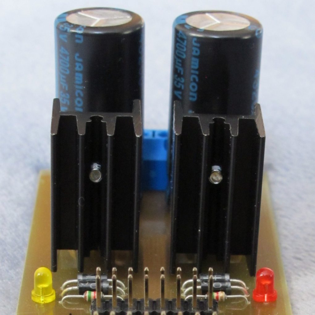
Heat sinks can’t touch each other, as they are on the different potential – 7812 heat sink is connected to GND, while 7912 heat sink to input (or filter output in other words). If you want to put both ICs on the common heat sink, be shure to put some insulation (f.e. mica) under them. I fixed both heat sinks few milimeters above the PCB to make air flow easier. Also don’t forget to add thermal grease or silicone thermal conductive pad between voltage regulator and the heat sink!
“Laboratory” tests
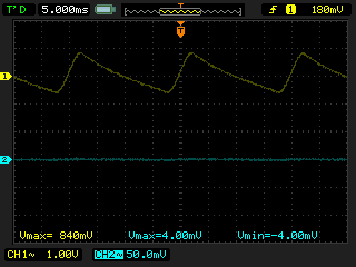
I’ve played with this PSU using 12 VAC, 1200 mA wall wart and tested the PSU with 22 Ω and 32 Ω load on each rail (I’ve found only 10 Ω and 22 Ω 10 Watt resistors in my drawer):
- for 22 Ω load, current draw from single rail – 530 mA, heat sink temperature – slightly over 60°C, output voltage with visible 1 Vp-p ripple, output current value is definitely too high!
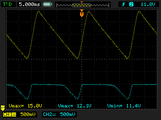
- for 32 Ω load, current draw from single rail – 370 mA, heat sink temp. – below 50°C, no visible ripple.
I’m using this PSU in my small eurorack system for around 3 years now with 6 modules with current load for each rail around 250 mA and it never failed. In conclusion I would say, 300 mA maximum load is a good compromise (but 350 mA will not harm it, too 🙂 (“What doesn’t kill your PSU will make it stronger ” doesn’t work here). Remember, you will fix your PSU inside a closed case and the temperatures will be greater then in open air.
End of story
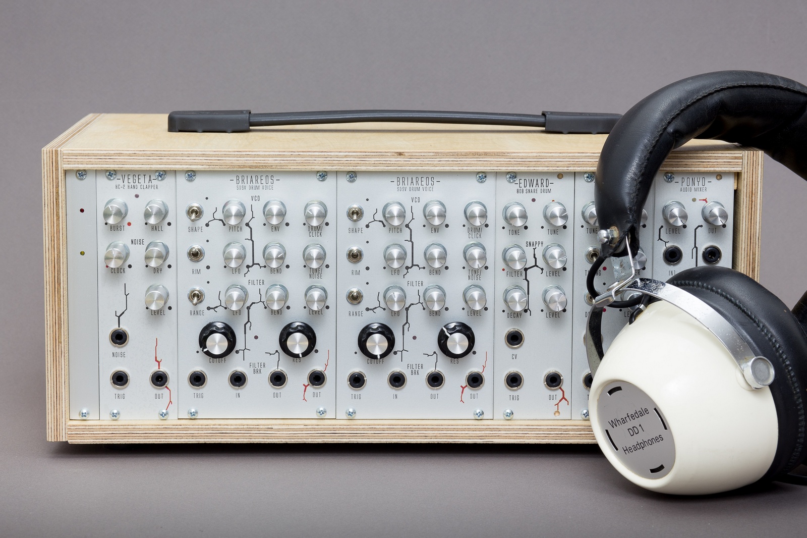
The Mini PSU sits in my Mini Case now.
No one can see it.
No one.
Before you do anything, remember: ~230 V can kill you without problems. If you don’t have experience with mains voltage, leave it to someone who has. You are using the project files for your own responsibility. Please be careful, don’t try to blow your small 1000 euro system with 10 euro power supply.
But still, I believe in you,
Cheers
Jack
THANK U A LOT!)))
Build my PSU by your project.
But, I’m changed tantalum caps, to USSR 1uf tantalum caps, and it works pretty good)
Could this be changed to 15v by just changing the rectifiers
I meant regulators not rectifiers by the way?
12 VAC 1A PSU output voltage will be probably too low to handle 7815/7915 properly, better go for somiething like 15 VAC. Cheers!
Hi, would it somehow be possible to use a wall wart with a 12VDC output instead? It seems nearly impossible to find one with an AC output.
Yes, it is very hard. If you don’t want to go with AC wall wart, the only way around is to use DC wall wart and DC/DC converter with +/- 12V. This combination is used in all popular small size modular power supplies. Cheers!
Take the wall wart apart and cut the output wires off, then locate the output from the transformer and connect there. Simples
Hi Jack! Could the big caps be changed for another value ones? 3300uf for ex? (I have ones I’ve recovered…)
Really nice site!
In the power entrance, is just needed to the two wall wart cables?
thanks
is just needed to connect*
May i use a 3A wallwart?
The datasheet for the linear regulators say they can deliver 1.5 Amps max. So yeah, i also would go for more than 12 V input, since they can go up to 35. Cheap Laptop power cables are around 19V and 2-3A. Maybe go to 50V caps then, elcos really don’t like to be stressed too much when it comes to voltages.
Hello Syntherjack,
Congratulations for this awesome website as it serves me and many other beginners a great deal. Your articles, tutorials and help, personaly, are immensely appreciated. Thank you for your time, effort and for sharing all the useful information. I have a question about the uPSU above. The schematic displays 1K LED resistors but the final board has 1.5K resistors soldered.
This is just to be on the safe side, right? Should I use 1.5K resistors as well?
And another question: I’m thinking of posting to my website your uPSU build with all the credits and references to your website. Is it OK with you?
Thanks
Would it work if instead of a wall wart I put a 12v transformer? ?
Dont suppose you have any PCB`s going/for sale , I dont have the space to make my own PCB`s (yet)
When everything feels urgent, it’s easy to lose focus and clarity. Step back, identify the most impactful task, and tackle it first. Protect your time with clear priorities and avoid reacting to every distraction. Focus is about choice, not just effort. What helps you stay grounded under pressure? Let’s share strategies!