Back to 2006
It was year 2006 and my electronic knowledge was extending. I’ve allready build a ICL 7107 voltometer and a dekatron spinner, therefore I felt I can do something really complex. One day I saw a Syntom II, an electronic drum synthesizer project printed in Electronics and Music Maker magazine, (E&MM, 1983). I decided – this one will be my next (and first synthesizer related) build. Here is a story of my big failure (with happy end).
Because I’m the best
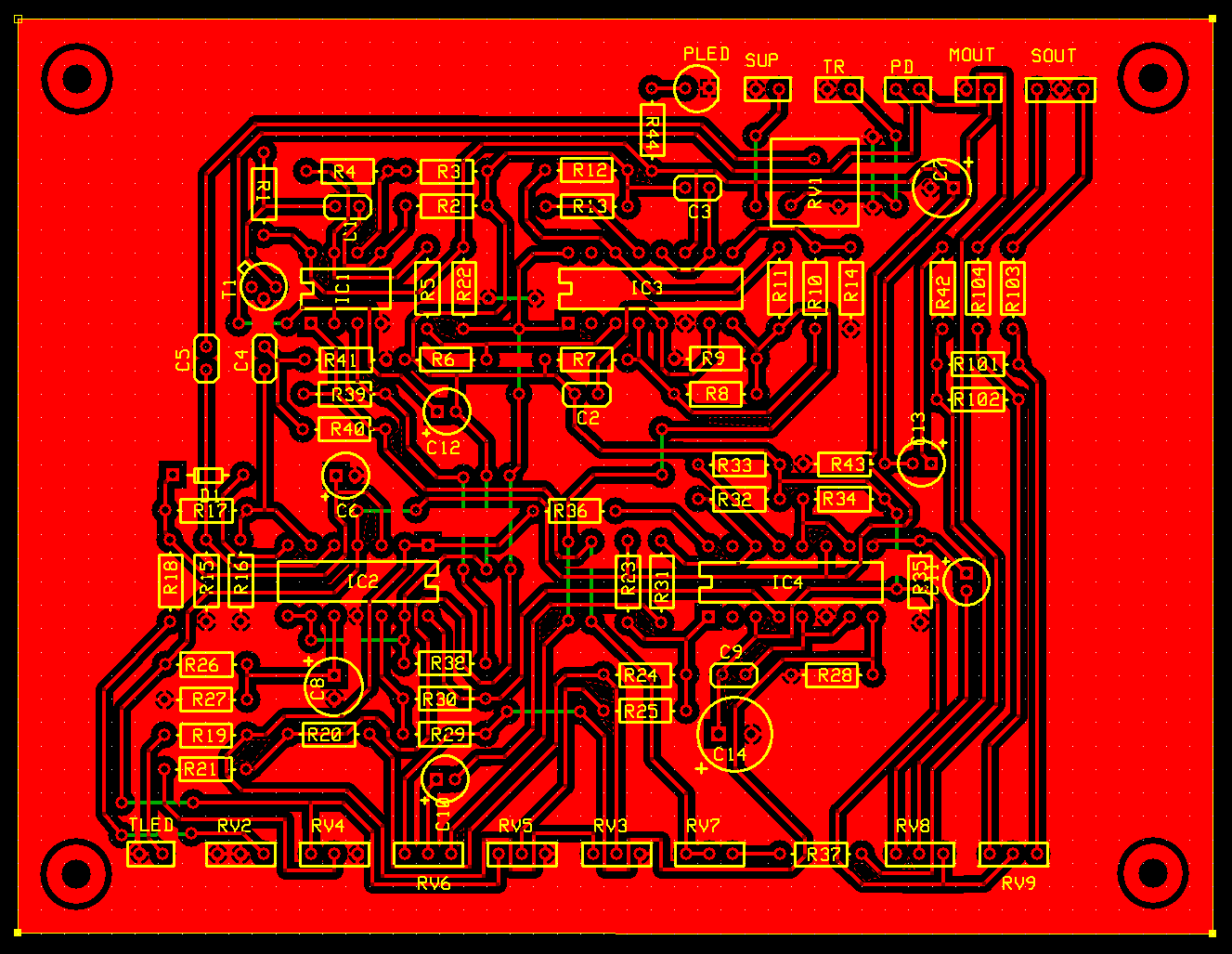
I felt really self-confident. I found a printable PCB template online, but I thought I can do much better. My experience included 5 designed PCBs, so I decided to create a custom one. The only PCB design software I mastered back then was ExpressPCB. And I got a great idea – why to use a expensive panel potentiometers, if I can save a lot of $$$ and use trimmers instead. What could go wrong?
Everything! I soldered it, bus wasn’t able to force to make any sound except of pops. I remember I spend a lot of time trying to figure out what went wrong. After a week of ineffective attempts I’ve dumped a project. It was one of my biggest fails.
Back from dead
Hard to believe, but the PCB (with all components) spent 12 years in a cartoon box. I used it as a shelter for old projects and a spare parts I will never use. As I digged thru all my stuff durning cleanings, I always saw it – Synthom II, a PCB of shame.
One night I though I will give it a try one more time. First of all, I took a multimeter, removed all ICs and powered a PCB up (+12 V and GND only, as Syntom is using virtual ground). All VCC points were at +12 V potential, except one, that was +11,9 V (and it was not a multimeter issue). I believe I tested those points in the 2006, but because I used an old analog multimeter back then I just missed the 0,1 V difference. When I turn the PCB, a delinquent revealed.
One of ground fill was unconnected. The rest of voltages were in ordnung, so I took an magnifying glass and inspected PCB with my own eyes. I found one more unconnected ground fill, near the envelope timing capacitor. I fixed those errors, but there was still no response from noise generator. It was time to check the schematic, possibly I made an error there.
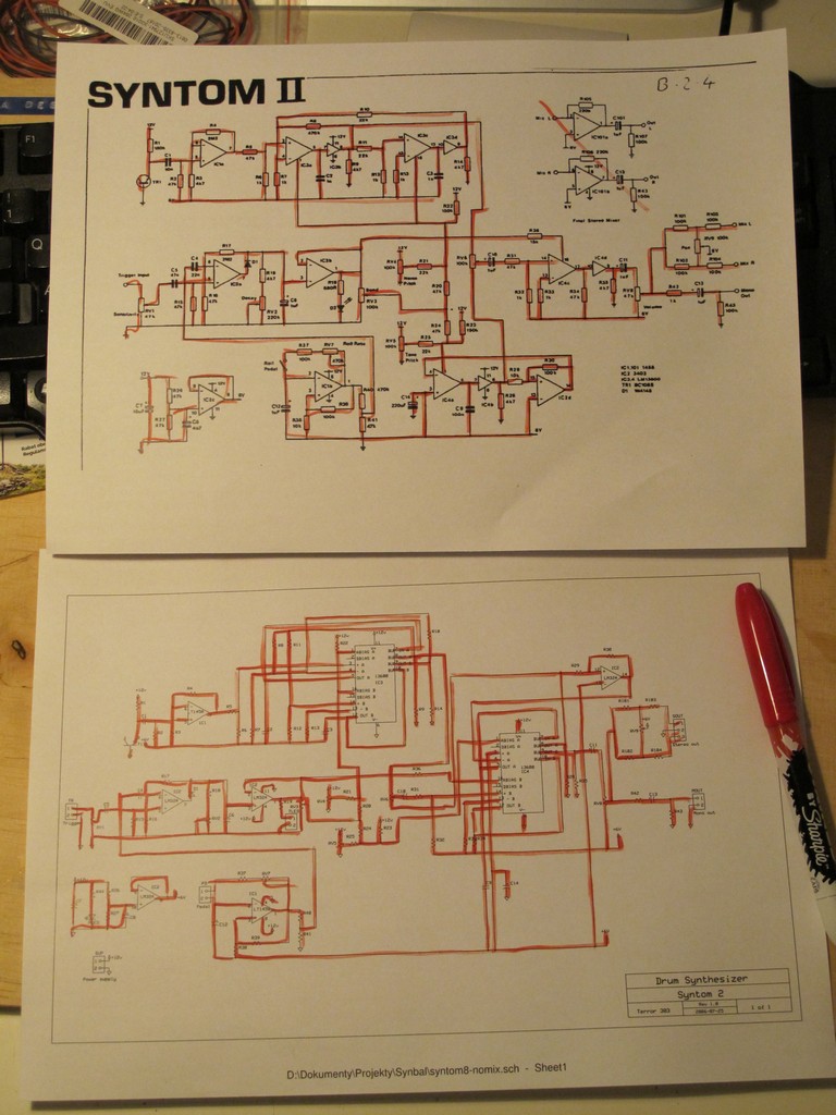
I printed the original and copied ExpressSCH schematic, then traced both with red pen. Unfortunately there was no error 🙁 The last thing that could be wrong were the noise circuit components. After checking BC107 transisistor PCB outline and a pin markings in datasheet, I’ve noticed, I soldered the transistor backwards. Seems like there was an error in PCB design software library.
After fast repair, the drum started to work. Now it was a time to eurorack it.
Euroracking and modding
There was no standard 2×5 eurorack power connector on the Syntom II PCB, mine also hadn’t one. I fixed it with small additional PCB. And as I had to include a new PCB, I decided to add a LFO to the existing design with noise and tone pitch modulation capabilities. The LFO was strongly inspired by Boss CE-2 LFO circuit. Because the LFO output oscillates around virtual ground (~+6 V), and the modulation levels of the Syntom varies from 0 to +12 V, when the LFOs output level goes up (from 0V), same goes the offset. But this can be compensated to some level with individual noise/tone pitch controls.
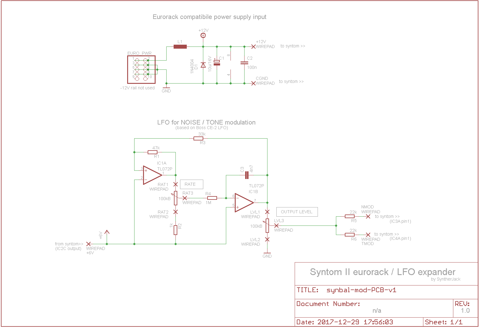
The size of the LFO/eurorack expander PCB matched my Syntom II design, so it could be mounted easily on the top of it. The virtual ground for LFO was supplied from Syntom PCB. The board is so simple, the whole circuit can be build on universal PCB. But I etched mine, because etching quiets me. There is nothing better then beer, cat and hot etchant in a jar.
LFO can modulate noise VCF cutoff (noise pitch) and VCO pitch, the control of mod depth is common for both generators. The drum synth structure is very similar to Coron DS8 – both drums using VCO/noise generator combo with LFO/bend modulation. The difference is Coron noise source cannot be modulated (it has 2 color setings instead), it also lacks drum roll generator. Originally the ROLL was controlled via external pedal – I used a simple push button placed on the fornt panel instead.
The block diagram of the modified Syntom II looks as following:
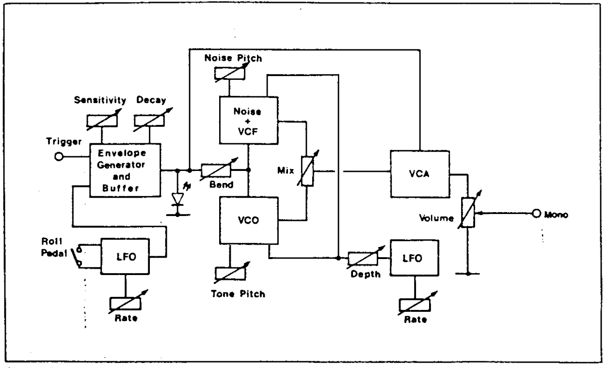
The trigger pulse is shaped creating simple envelope with sharp, fixed attack and decay controlled via DECAY potentiometer. The same envelope is used for VCF/VCO BEND and output VCA. Roll LFO creates a train of pulses mixed with external trigger signal (so you can actually use a module without any external triggering hardware, like sequencer). Both noise source and VCO have a seperate pitch controls. Pitch of noise is changed by controlling cutoff frequency of the LP filter connected in series with actual noise generator. The output ratio between both generators is set via MIX potentiometer. The only additional circuit is LFO on the right, with RATE and DEPTH controls. Original Syntom has optional stereo output with PAN, but I skipped it.
Lets build it!
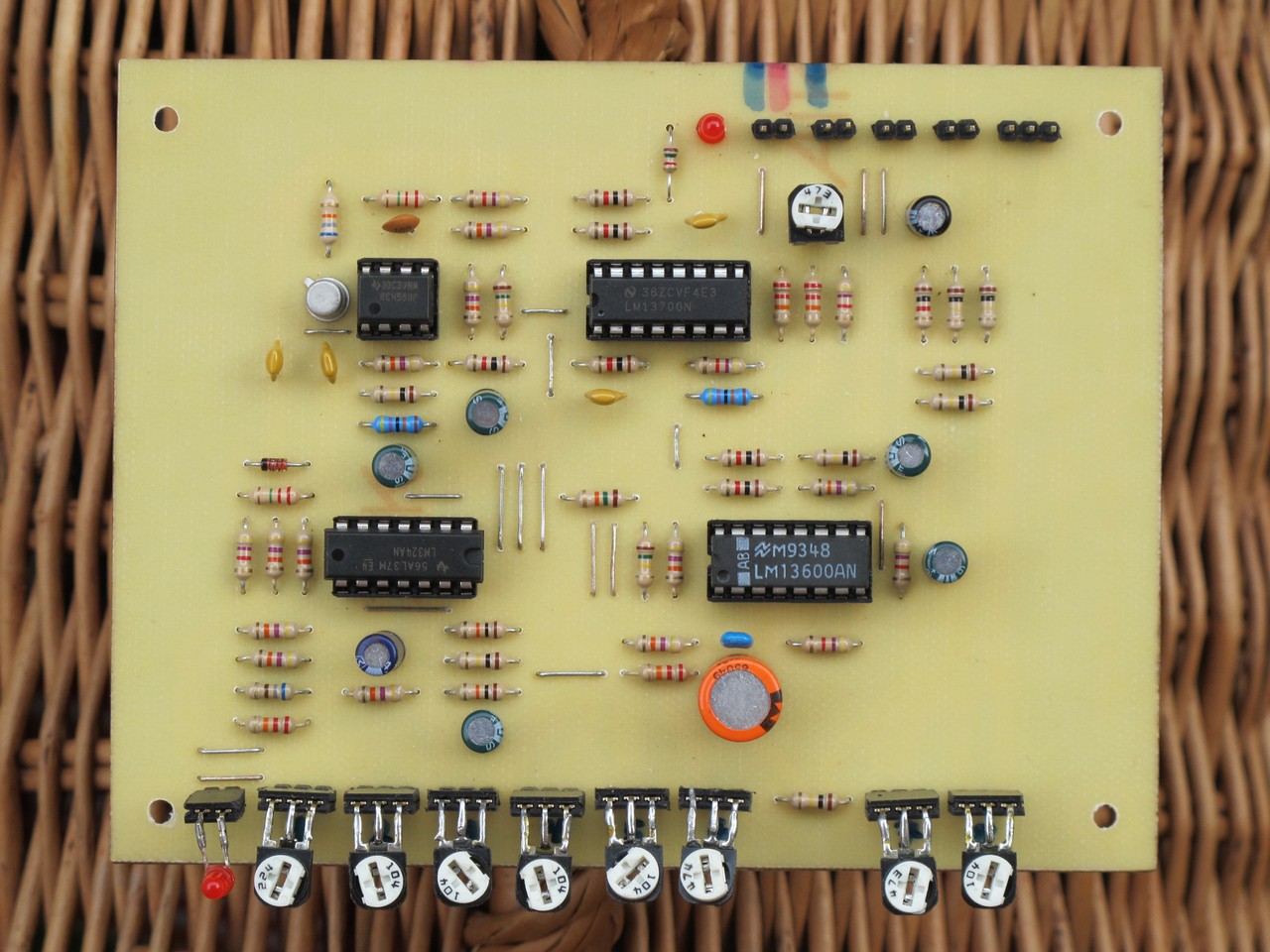
It is my standard quality eurorack build, with 2 mm aluminum front panel and 0,5 mm metal sheet PCB holder. You can read about whole process in a series of my articles on DIY eurorack modules. I used, as always, 16 mm dust sealed Alpha Taiwan potentiometers and my favourite quality noname jacks bought at local store.
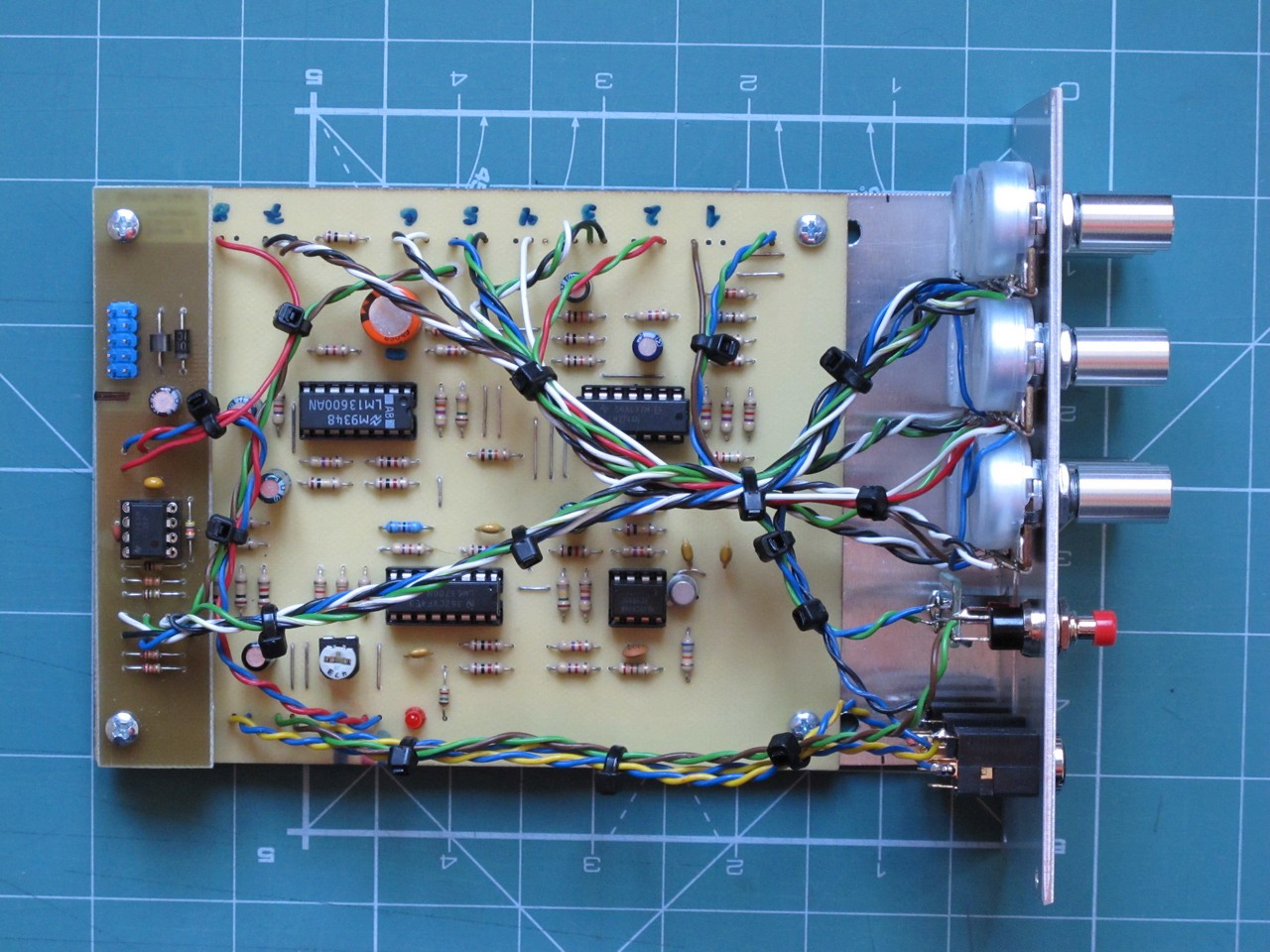
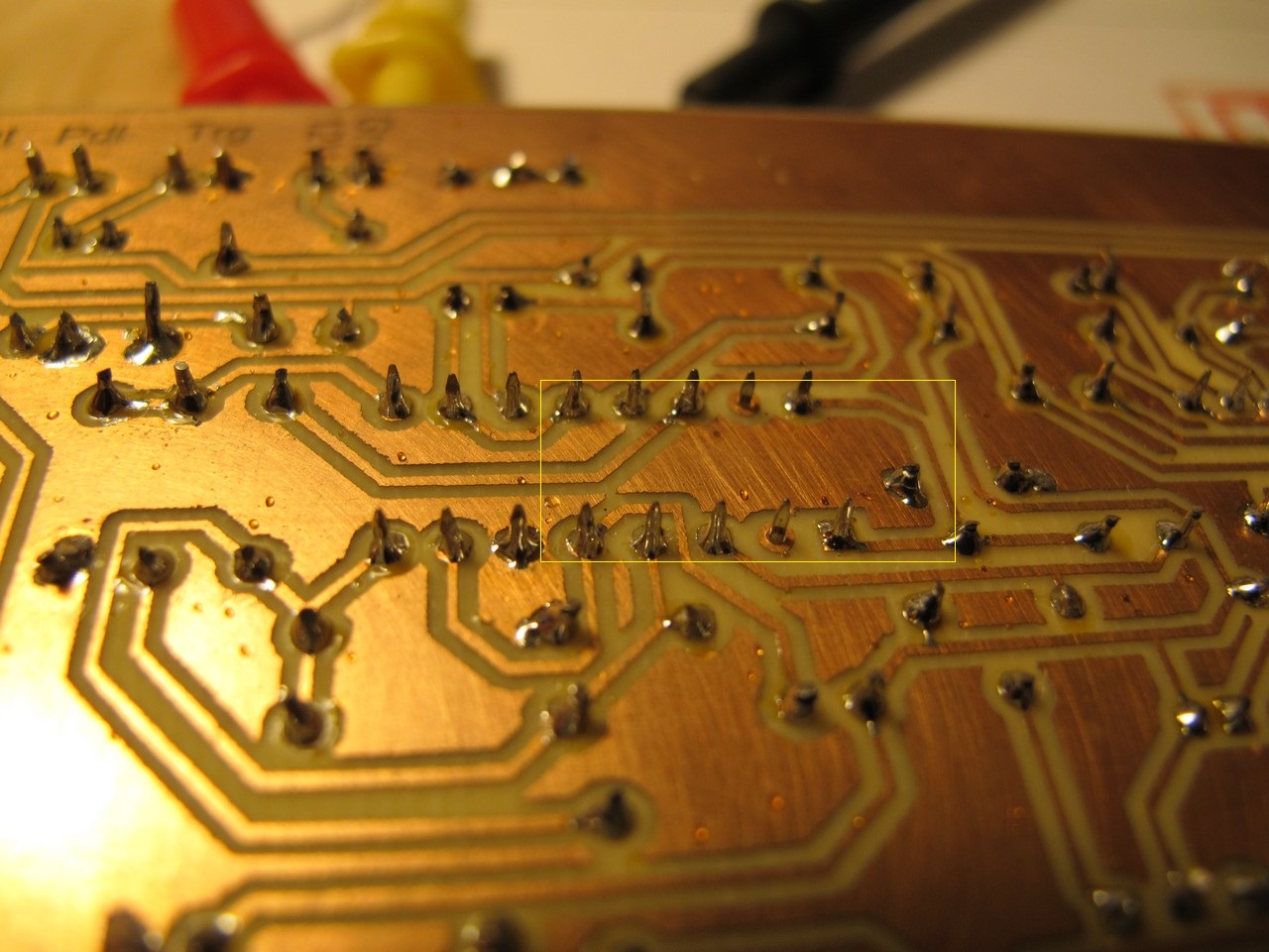
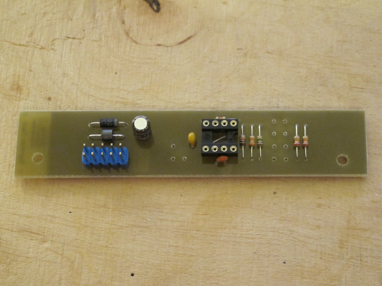
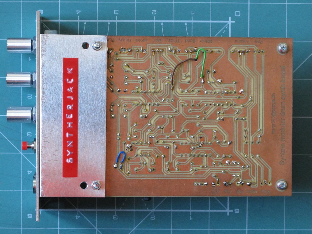
Copper side of the PCB looks not so neat. I drilled a hole to secure 2 LFO wires (brown and green), soldered directly to traces (not a great solution, but it is easier to solder as wire aligns with trace, also the propability of short-circuit reduces). On the bottom left you can notice a blue wire that connects “ground fill orphan” with the rest of the plane. Just above it you will see a reversed transistor. Just few centimeters below the PCB center, under an IC, there is another gorilla connection, made with silver plated copper wire.
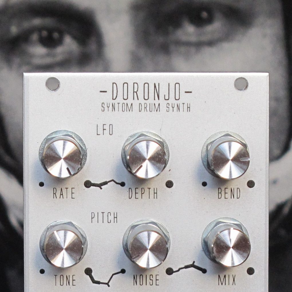
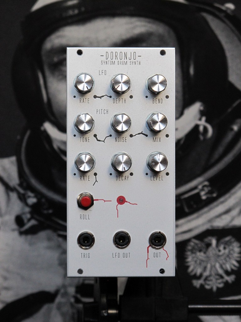
And this is how Syntom II front panel looks like. The name “Doronjo” comes from the name of one of the characters from a cartoon I liked as a kid (you can quess which one was it). How I designed the front panel and what’s an idea behind such control placement?
First of all, I tried to place certain potentiometers/jacks in a scheme common for all my drum modules:
- TRIGGER pulse input on the bottom left,
- sound OUTPUT on the bottom right, the only jack socket marked in red,
- output LEVEL potentiometer above the OUTPUT jack,
- trigger LED always in the middle – it could not be placed over the DEPTH potentiometer (at the top of the module), due to lack of space, so the only alternative was in the fourth row (and also my other modules use the same trigger LED position – Kazuya, Briareos and SnapClap ).
The rest of the controls are arrangement rather logically:
- automatic modulation LFO/BEND in the first row – the root-like connection between RATE and DEPTH indicates they work as LFO group,
- manual modulation (pitch TONE/NOISE) in second, along with MIX ratio between VCO output and filter (noise) output – MIX knob in the middle (between TONE and NOISE) would be more intuitive, but then the LFO and PITCH labels would be not aligned :/; also MIX and LEVEL both control audio levels and it would be nice to have them close to each other,
- third row contains rest of controls – LEVEL on the right by default; DECAY had to be in the middle, because RATE is functionally connected with ROLL button and they should be as close as possible.
That’s how I ended with this front panel design.
I will add a demo later. If you need a original build plans, call me.
Cheers
Jack
Please where do you get those silver knobs from