There is a story behind this module. Using my countless stupidity, i menaged to broke both hands while riding my bike. After that, i had a lot of free time, but i wasn’t able to many things. With some training i menaged to master computer mouse with partially plastered hand and keyboard striked with pencil. So I clawled thru internet, looking at cats and music videos on Youtube.
Then I stopped on this one:
Yes. There it is: Simmons SDSV. It was time to take a closer look.
Via Wiki:
„The Simmons SDS 5 (also notated as SDS-V or SDSV) was the first viable electronic replacement for acoustic drums. It was developed by Richard James Burgess and Dave Simmons, manufactured initially by Musicaid in Hatfield, UK, and commercially released in 1981. (…) The standard SDSV was loaded with 5 modules: Bass, Snare and three Tom Toms, which looked almost identical, with controls for noise level, tone level, bend, decay time, noise tone and click drum control which added extra attack derived from pad impact. Each module’s parameters were optimised for the drum it was designed to emulate. Optional Cymbal and Hi-Hat modules were also available with open and closed hi-hats controlled from an external pedal. There was also a mixer section with individual volume control for each module (only into the mono/stereo output) and controls for pad sensitivity.”

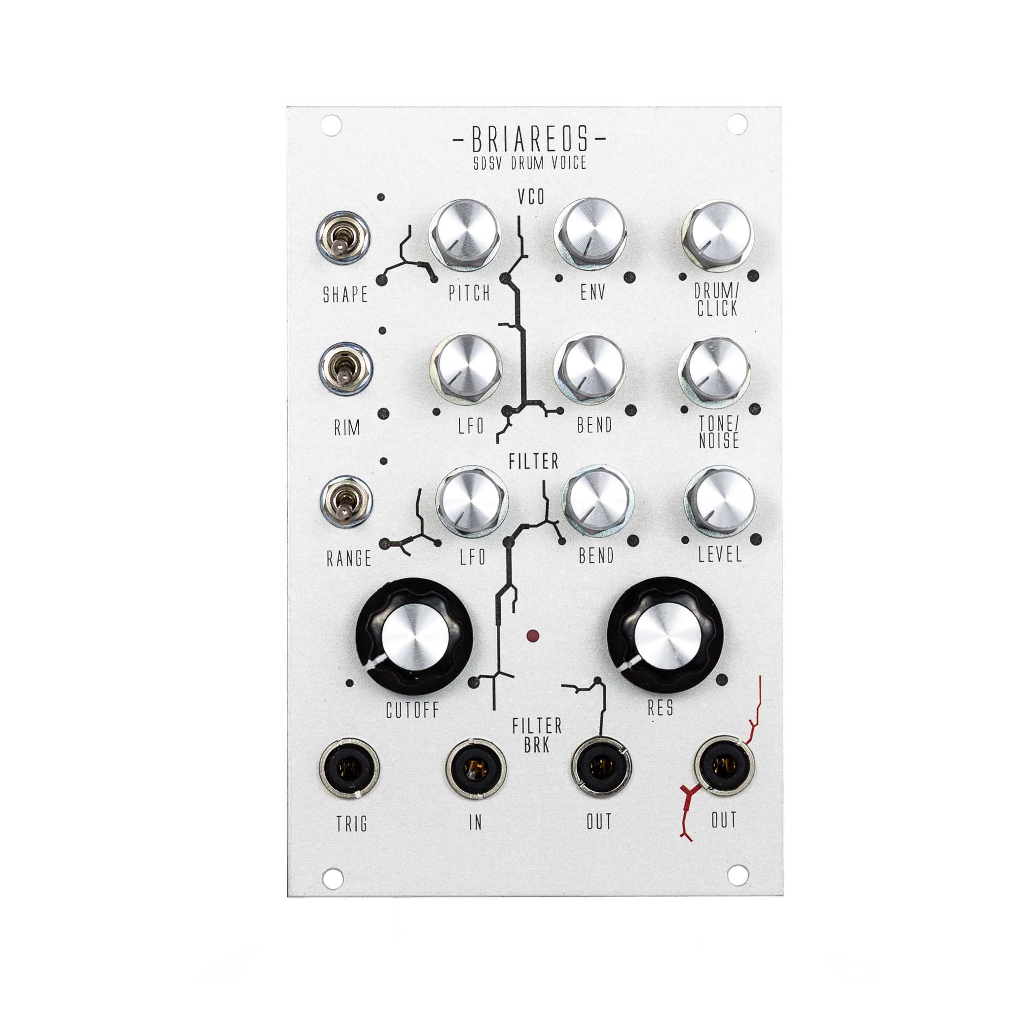
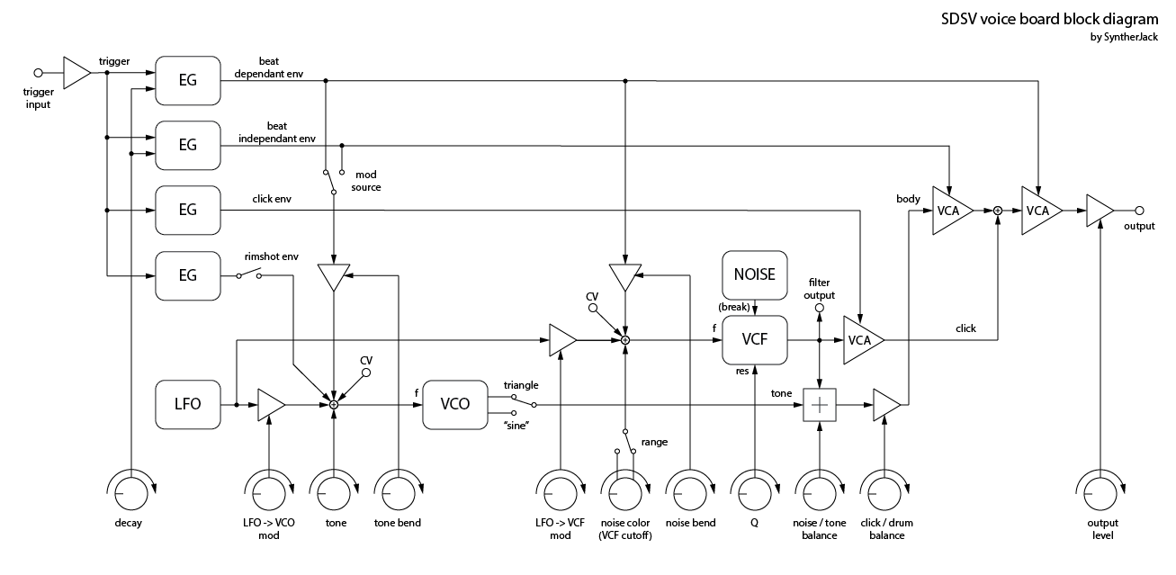
The structure of Simmons SDSV drum voice is quite unique. Sound generation engine is very simple (one VCO, one noise source with filter and LFO with fixed frequency) – the power of Simmons design lays in the modulations.
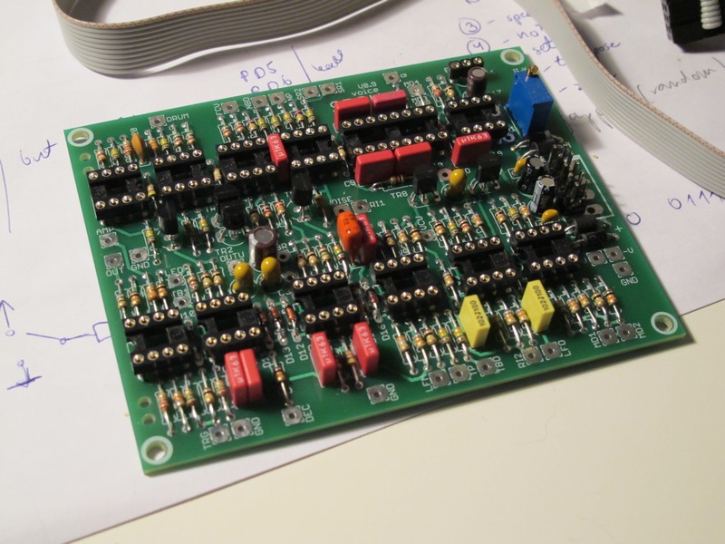
I looked for schematics, there are only two You can find: one hand-drawn with english/german markings, second comes from the service manual – both have errors and some missing values. I decided to make one PCB, that allows to recreate bass, snare and tom tom sounds. Cymbal and hi-hat modules use additional digital circuit board with sound sample stored in EEPROM and I didn’t have an acces to it. Circuit errors were quite obvious, missing component values were read from original PCB photos taken by private SDSV users.
Designed PCB is two sided, 80x100mm (half eurocard). I DIYed 2 modular synthesizers modules, but they don’t make the most of the SDSV circuit. I didn’t included LFO speed control, CV inputs for LFO, VCF, VCO and output filter switch.
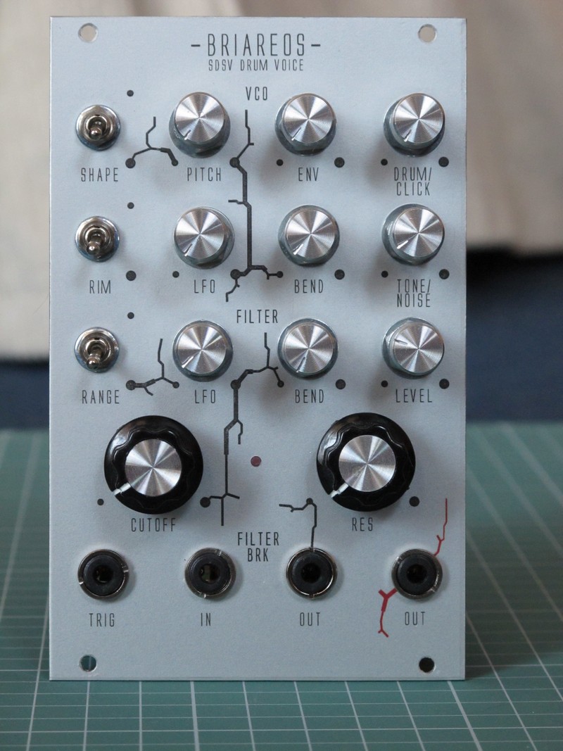
Below you will find 3 demos of the module. First two are fully functional prototypes, the last is a final demo of a finished eurorack module. I not very good at demos (they are boring as ****), but believe me, this module have incredible range od sounds. You can make bass (also 808 style, with long decay sine), snappy snared and hi-hats.
Prototype demo:
The final module demo:
Oberling from MuffWiggler forum made a very good demo of his 6-voice SDSV DIY sound system based on this project. You can check a documented building process (in german) on his blog BassBude.
Technical data of the SDSV voice:
- Topology:
- 4x EG (simple AR),
- 3x VCA – CA3080 based,
- 1x VCO – triangle and filtered triangle outputs,
- 1x LFO – triangle core,
- 1x noise generator (transistor based),
- 1x VCF – SSM2044 based.
- Controls (much more then in original circuit):
- decay,
- VCO tone,
- VCO sweep,
- LFO -> VCO modulation depth,
- noise tone – filter cutoff,
- noise sweep,
- LFO -> cutoff modulation depth,
- filter resonance,
- noise / VCO balance,
- drum / click balance,
- output level,
- rimshot modulation on/off,
- VCO output filter on/off,
- noise sweep range.
- I/O:
- trigger in,
- filter in,
- filter out / noise out,
- drum out,
- trigger LED.
PCB is designed for some more modifications, not shown in demos: LFO speed, LFO speed CV, VCF cutoff CV, passive output filter for hi-hat sounds, VCO modulation source – EG1 or EG2.
- Power supply:
- 50 mA @ +12V,
- 20 mA @ -12V,
- works also with +/-15V.
This is not the end. I decided to add digital part of the circuit found in hi-hat modules. Check my SDSV expander!
Cheers
Jack
This article uses material from the Wikipedia article “Simmons_SDS-V”, which is released under the Creative Commons Attribution-Share-Alike License 3.0
Warning for MOTM users (thanks to mangros)
[…] for anyone making this with a MOTM power connector – the silkscreen outline is wrong. The header tab should be at the other side (closest to the board edge).
This looks very interesting. I love the sensitivity of the original simmons pads with sdsv modules compared to any recent roland trigger module or midi trigger interface. How is your sensitivity set? I’d like especially a maximum input sensitivity so I can play the pads really softly, will this work with your module? I’ve still got the original pads.
Hello, I tried to keep my SDSV interpretation as close to original as possible, but to be honest, I didn’t tested how sensivity works :/ But in theory, all I need to do is check how it responds to different trigger levels.
Hi, I would like to recreate not only drum pads but as well the module, for myself. may I ask for help in case of the module? galaxyhunter.space@gmail.com