The purpose of my passive volume control build was simple – I just needed an analog regulation of headphones loudness my laptop was missing (and nothing feels better than a potentiometer knob in your hand). This project was so incredibly boring, that at first I didn’t want to write about it. However, apart from its simplicity, there are several interesting techniques I used and would like to share with you. And forgive me, it will be more a photostory than a proper technical post.
Schematic & parts
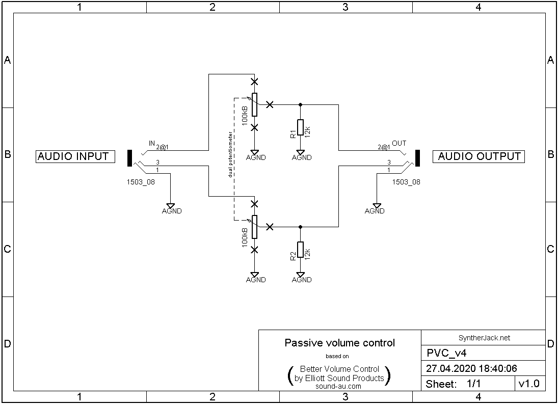
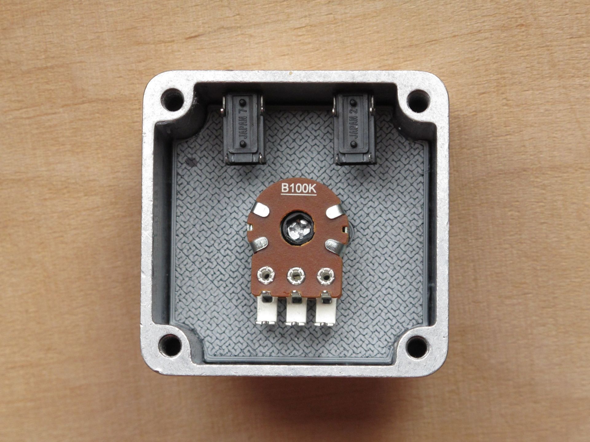
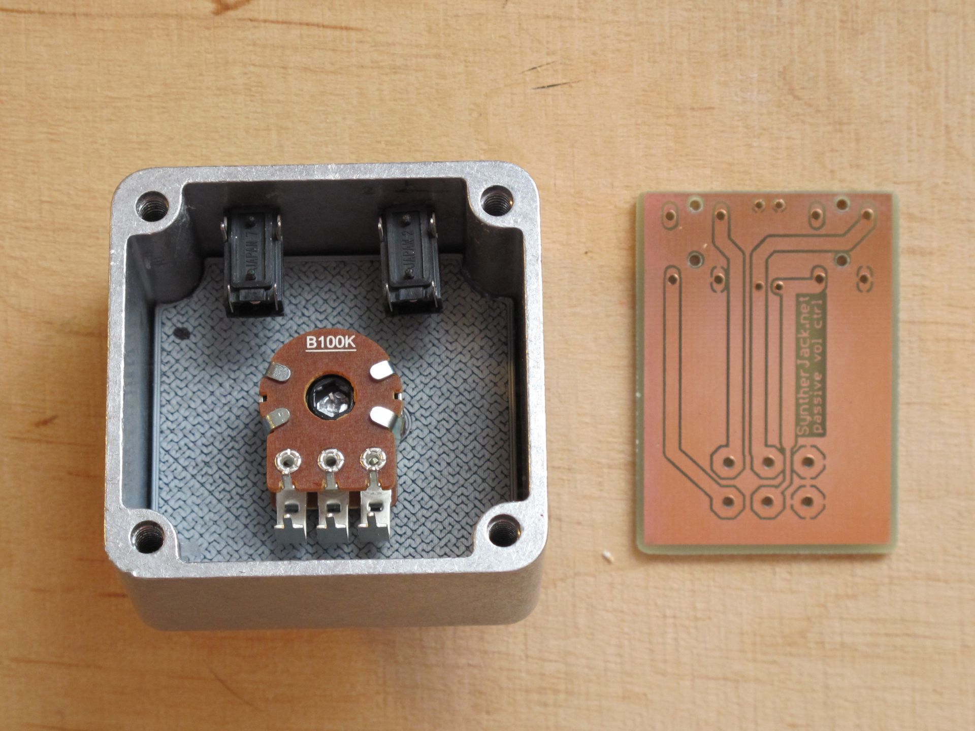
The schematic of passive volume control includes only 5 main components: dual linear potentiometer, 2 resistors and 2 mini jack sockets. It is 1:1 copy of Better Volume Control from Elliott Sound Products. The interesting thing is, it uses linear potentiometer along with load resistor to get smooth increase in volume level. For more info on theory please refer to homepage of the original designer.
The list of used components:
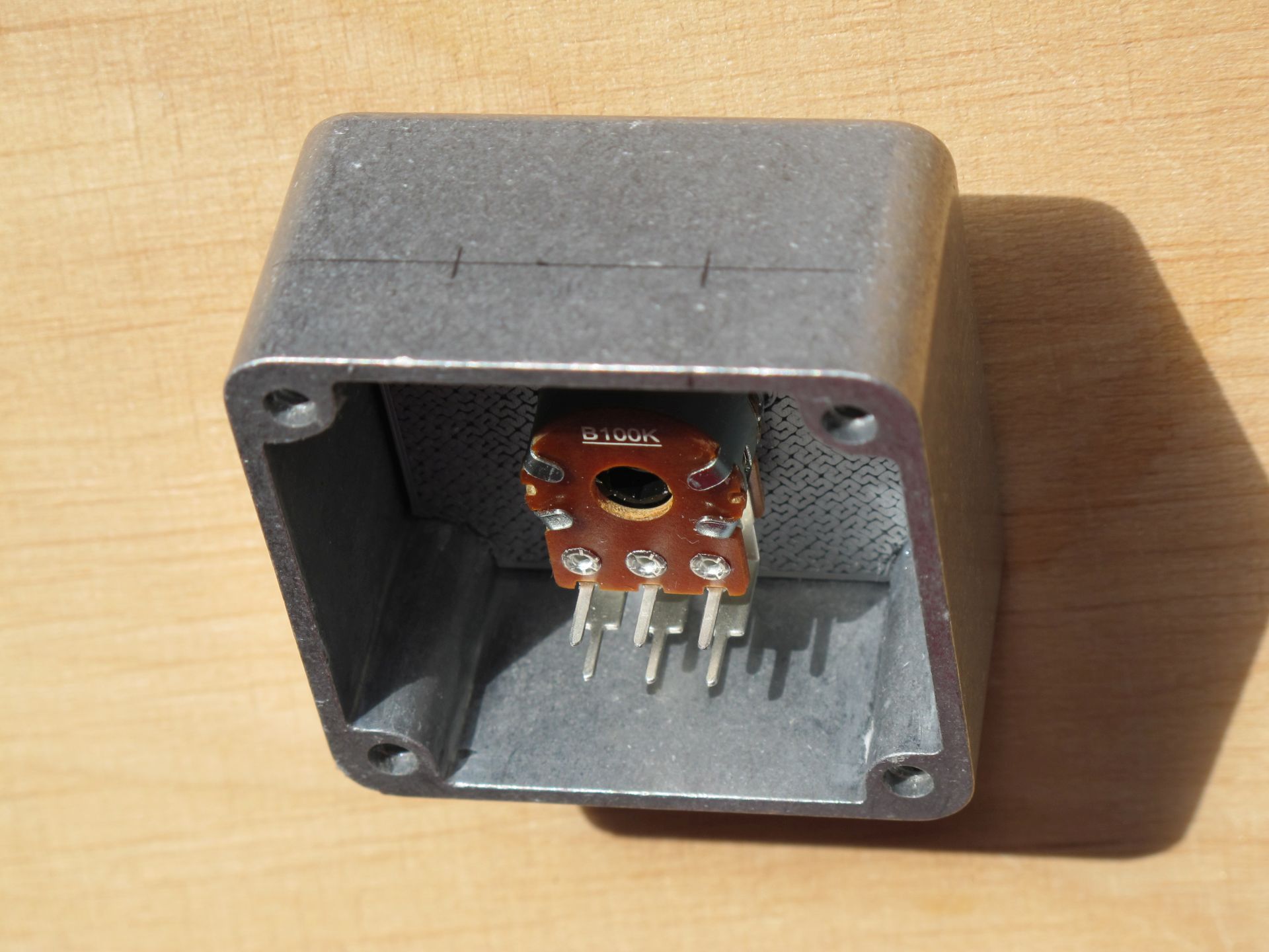
- 1x dual Alpha Taiwan 100 kB (linear) potentiometer, RV16A01F-41-15R1-B100K
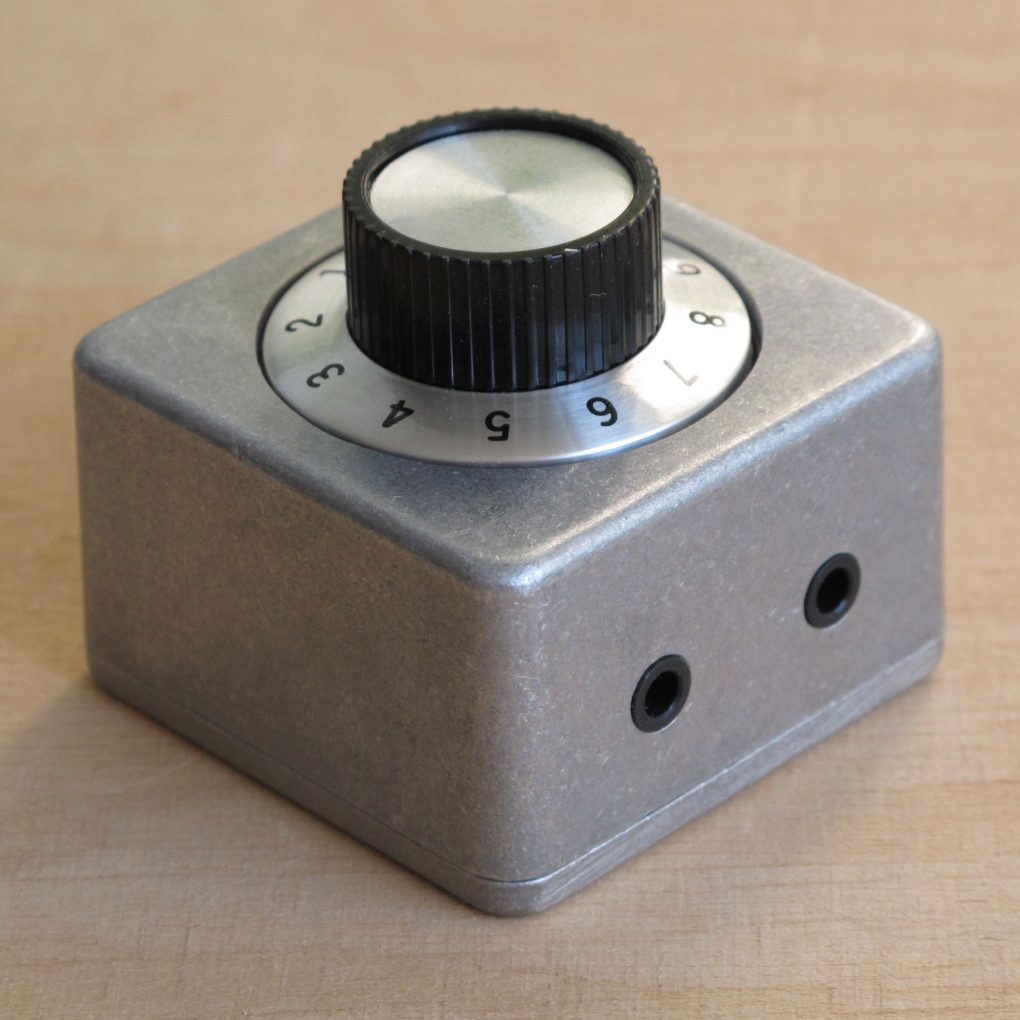
- 1x SCI RN-114A potentiometer knob (similar to Tayda Electronics TE-KN-138A, but with smoother typography),
- 2x 12 kΩ resistor, 1%, 0,6W,
- 2x mini-jack socket, Lumberg 1503-08 (small and high quality),
- 1x Tayda Electronics 1590LM aluminum case (a bit similar to Hammond 1590LM, but cheaper).
The fuzzy idea
This is where things got more interesting (but they were still felt quite boring back then). I wanted to get a cool safe look with a very tight-fitting knob recessed into a case. Because I never experimented with such knob placement and haven’t seen a lot of them in DIY audio stuff, so it was very tempting. I went with the “greedy” design approach – I was thinking what will be the next step after I finished previous one. At this point I knew only where knob will be placed and that’s all.
Initially I wanted also to use mini jacks for input and output and an additional regular 6,3 mm jack as second output for professional headphones (to eliminate the need for an adapter), but the idea was dumped as case turned out to be too pokey.
The build – potentiometer knob opening
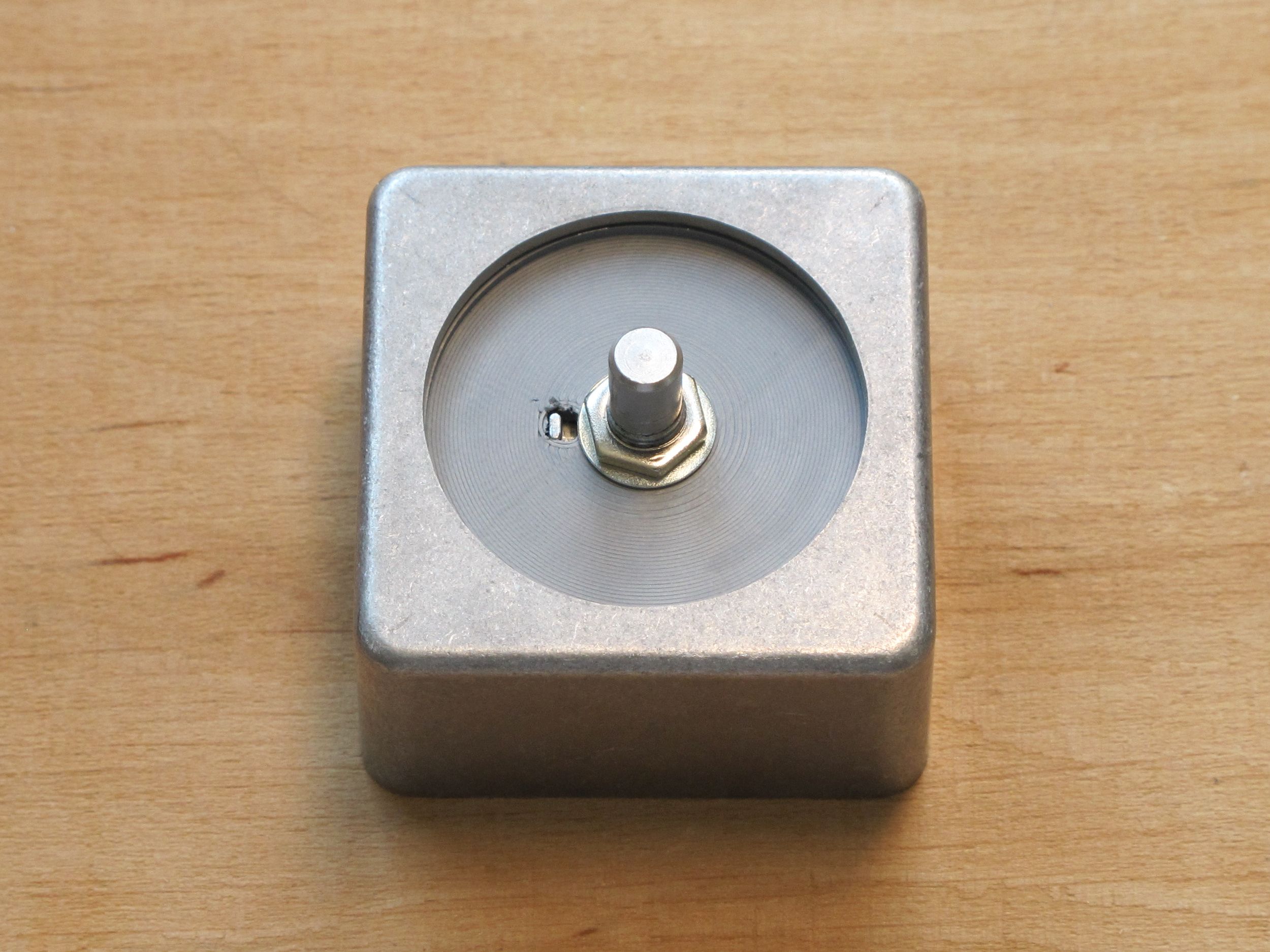
I decided to use small 1590LM aluminum case from Tayda Electronics, cheap and robust, unpainted with raw industrial feel. (A very conveniently thing to say if you are sick of spray painting). I marked the center of the case and draw a 38 mm circle with calipers, then drilled a series of small holes inside it. Luckily it doesn’t have to look beautiful now.
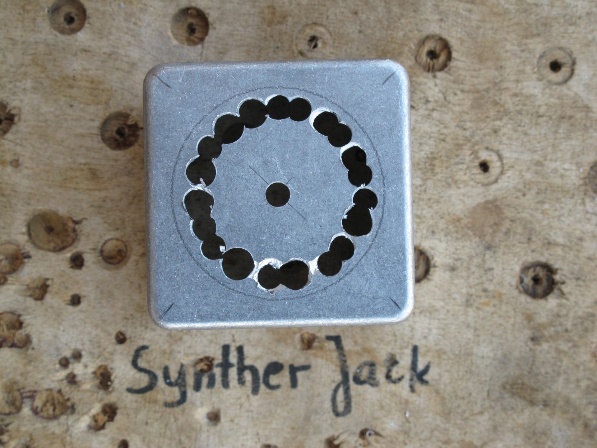
Then I used slightly larger drill and small round file to join holes where possible and removed the irregular interior of the circle. Of course, I forgot to wear protective gloves and the remaining edges were sharper than I’ve expected.
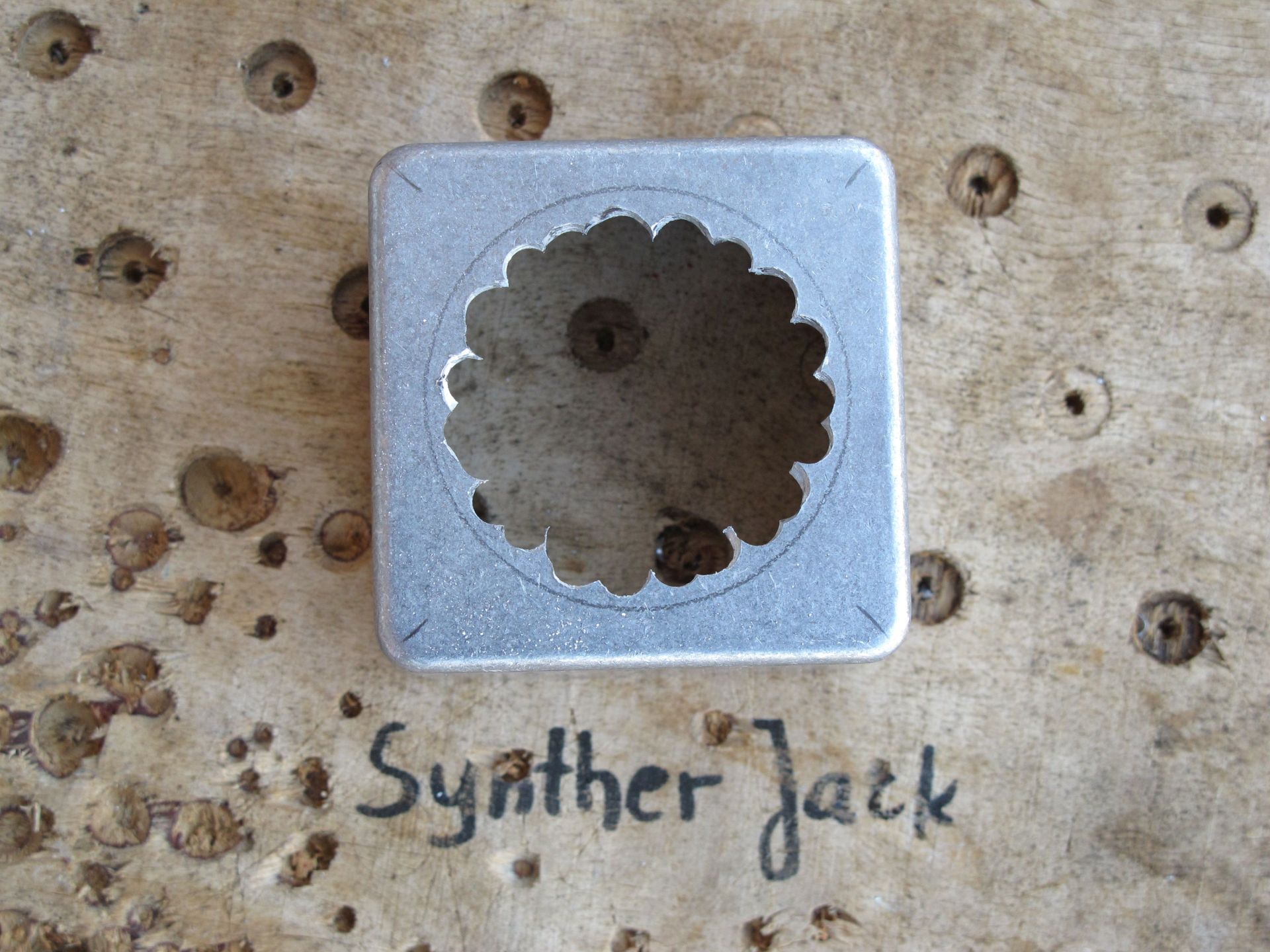
The rest of the job was finished with semicircular files. Filing and smoothing took just few minutes, as the case material is relatively soft. Result was not bad, not bad at all, but I wouldn’t like to repeat it. The problem appeared – how to mount a potentiometer?
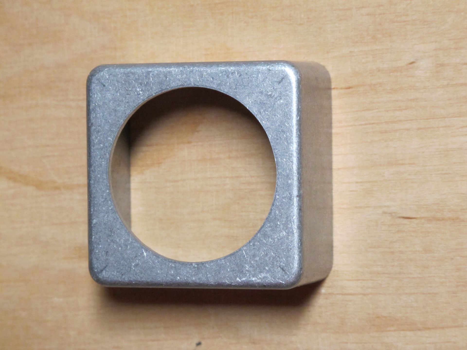
Drilled hole was exactly 38 mm in diameter, only 1 mm larger than the knobs. This means the potentiometer must be also placed very precisely, while this means the fixing hole must be drilled near perfectly. I own only a small Proxxon 12V system drill stand, so extremely precise positioned 6 mm hole was way out of my capabilities.
…and here comes the 3D print.
The build – potentiometer holder
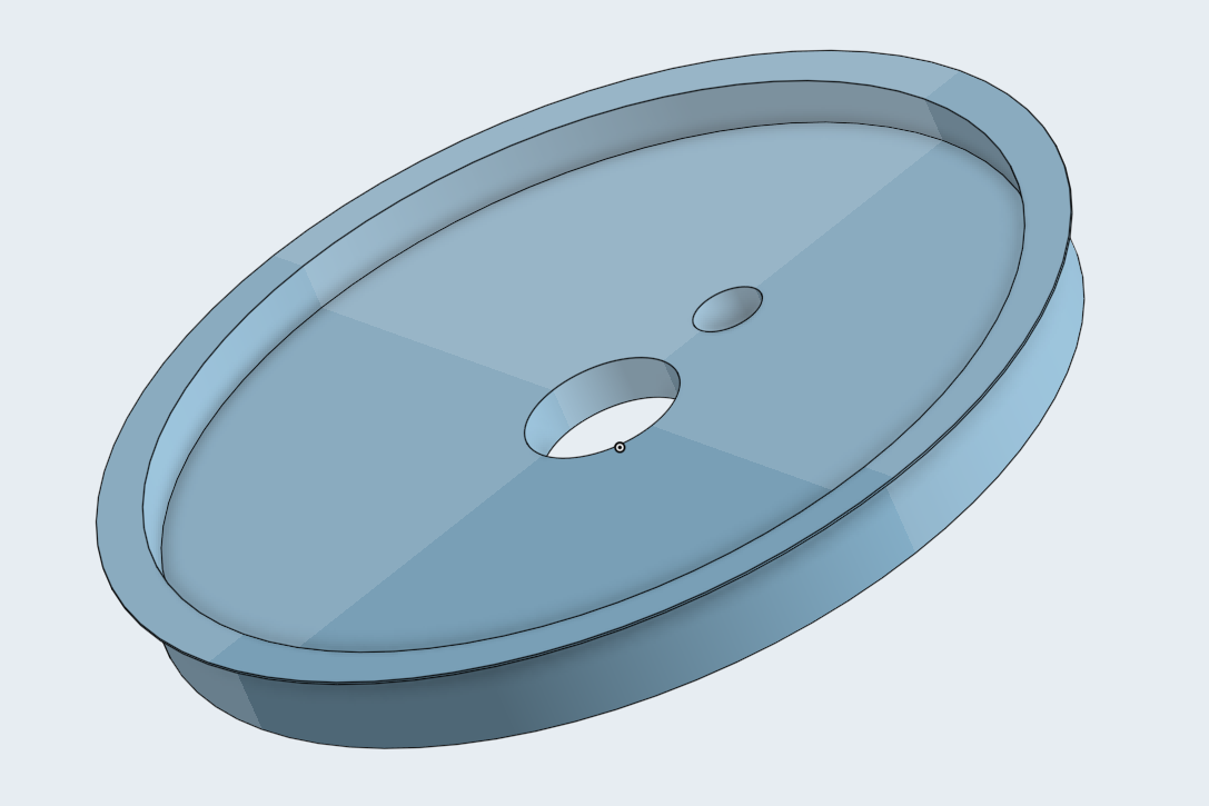
At first, I was going to use a PCB laminate with hand-drilled mounting hole as a potentiometer holder, but after a while I thought it will be much simpler to print a whole bracket on a 3D printer. After fast measurements I designed a part in OnShape and send the project to my friend, a proud Prusa owner. 3D print is generally very useful for internal standoffs, supports and spacers, as is usually strong, but ugly. Some other 3D printed parts were used in my Glidophone project.
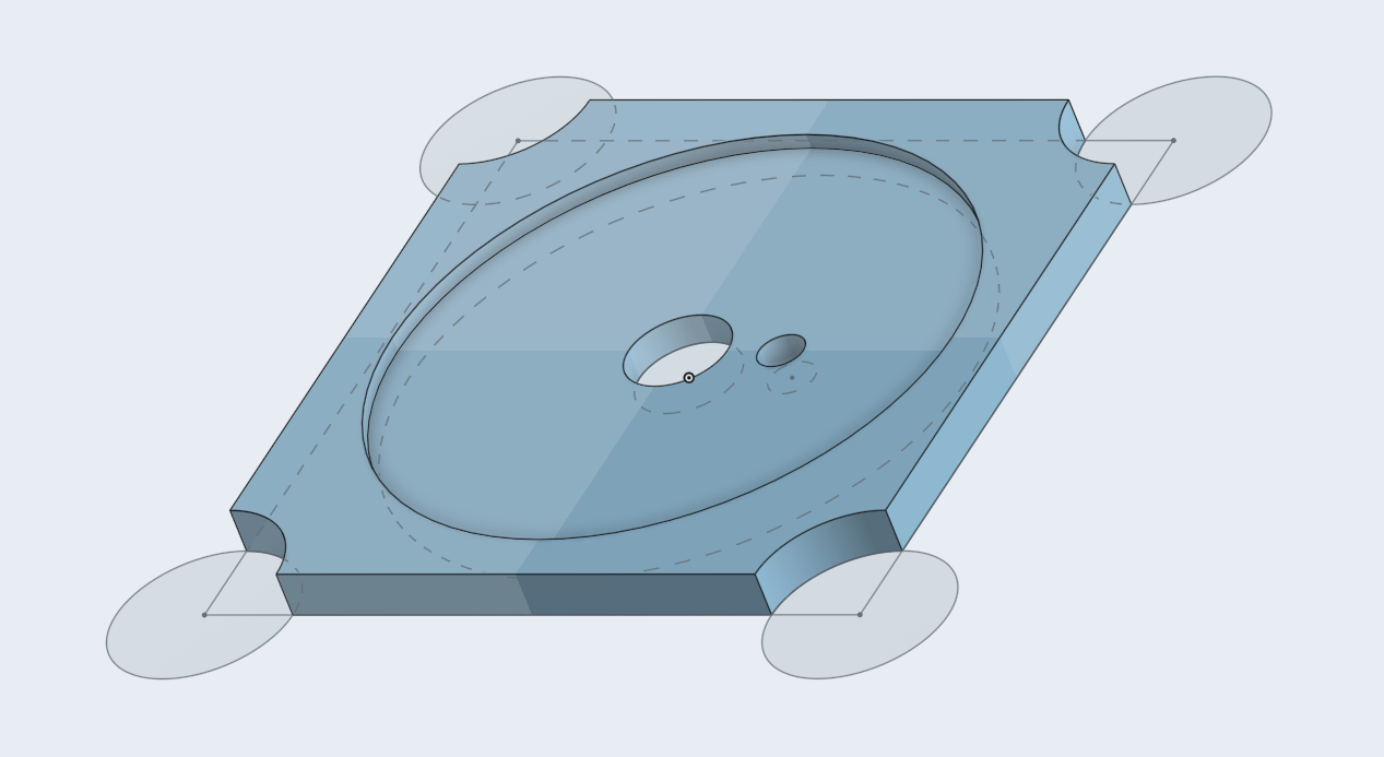
3D printer is much more precise than me and unlike me doesn’t hurt itself during work. It was important as I needed the knob shaft to be in the center of drilled opening. Of course, I checked the free play between knob and a shaft – and mostly thanks to shaft cylindrical shape, fit turned out to be very tight.
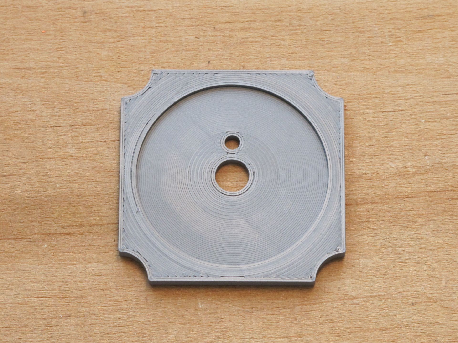
The supporting 3D printed part was glued to aluminum enclosure with epoxy. But I wouldn’t be myself if I didn’t make a mistake in the design. The hole for this little unnamed protruding piece of aluminum sticking on the side of potentiometer turned out to be slightly to close to the center – I had to use file to fix it. It will be covered by the knob anyway.
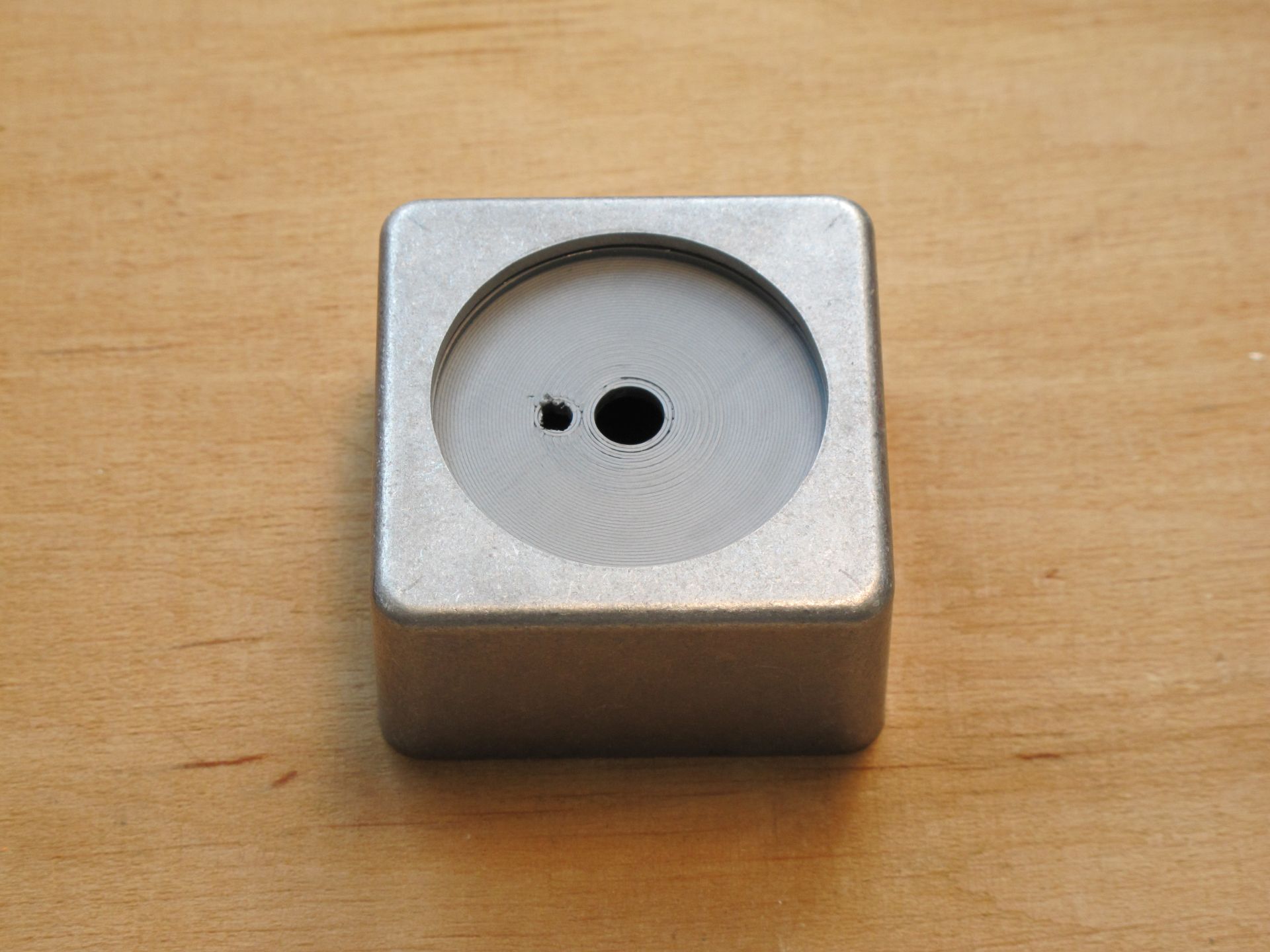
Then I installed the pot, pushed few times if the glue is holding strong, fixed the knob and rotated to check if the surrounding clearance is even. It wasn’t perfect, but acceptable. The next part of a puzzle – jacks (and 2 resistors)!
Edit: Now, when I am thinking about 3D printed insert design I think, it could be done a bit more clever. It will be independent of opening imperfections, unfortunately look less sleek with a narrow collar (~2 mm) and low (~0,1 mm) around the knob. Just another idea probably worth trying.
The build – Jacks
I chose my favorite Lumberg PCB mounted (and not enclosure mounted) jack sockets. This was going to cost me a lot of trouble. Firstly, I marked a jack position inside a case – just drew a round outline of a socket pushed against the facet. Then I set more or less a center if it. As the jack was to close to the screwing section of the case, I marked with arrow it should be moved and draw a new center (small dot in the shape of arc).
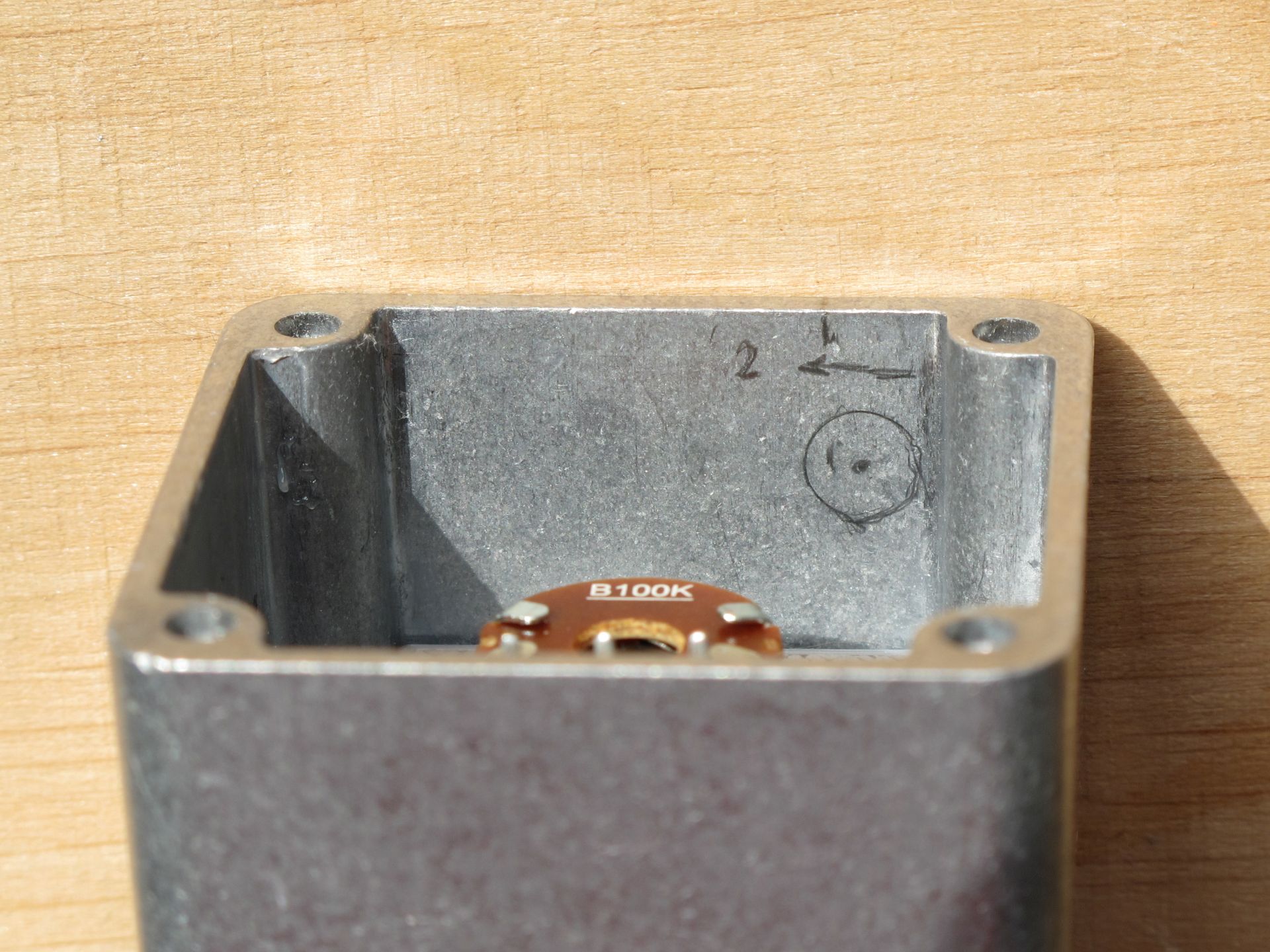
I measured the distance from jacks center to the enclosures top and marked it with the line of the other side of the case. Then drew a line on the edge of the case (just above the arrowhead), so I could get a horizontal position of the socket placement. This way I got the exact position of the jacks on the enclosures outside, so I could drill a hole supporting them (the fitting is very tight).
From this perspective jacks fit perfectly – but in reality they are fixed a bit to high in relation to the potentiometers body. It wouldn’t be a problem if I planned to just wire them, but my plan was more sophisticated (as long as you can call a plan of connecting 5 parts together sophisticated). And besides, the jacks were PCB mounted and need some support to not fall when plug was inserted.
In this point I had two options:
- glue sockets and wire all the components, or…
- design state of the art PCB.
For me, the choice was obvious.
The build – PCB
As I am not the hot glue guy, and I am moving somewhere into “I hate wiring” region, I decided to design a PCB to connect all parts (yes, I also think it is an overkill). You may already noticed, as PCB is soldered onto pot and jacks terminals, its design had to be very careful and precise. As the most important were correct pot and jack positions, at first I printed few designs and check if they fit.
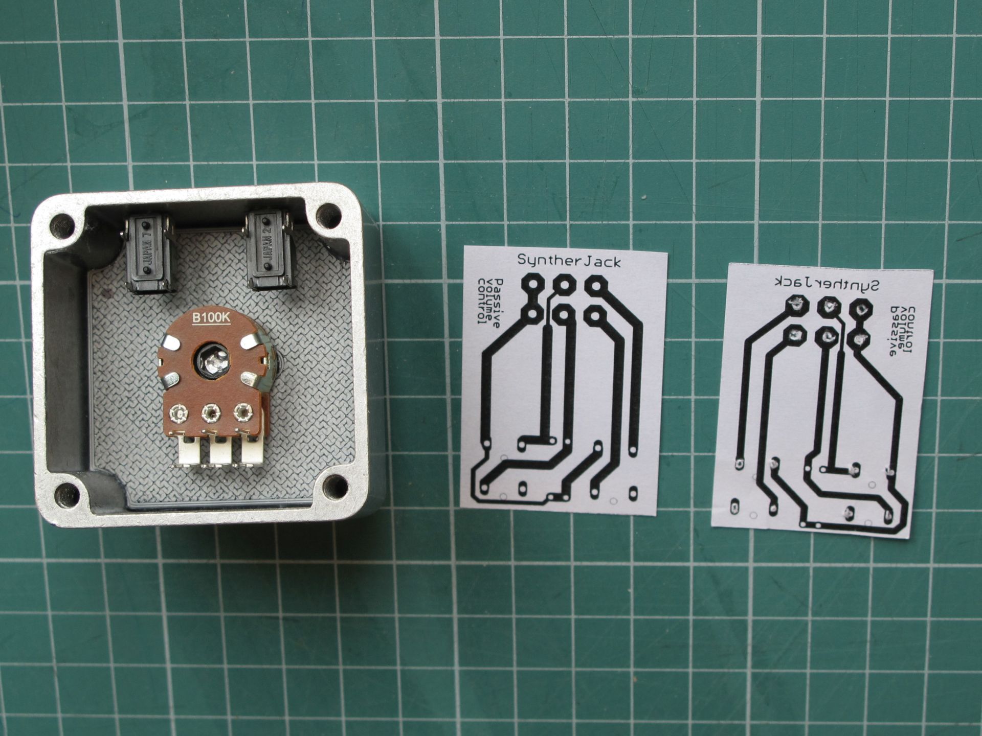
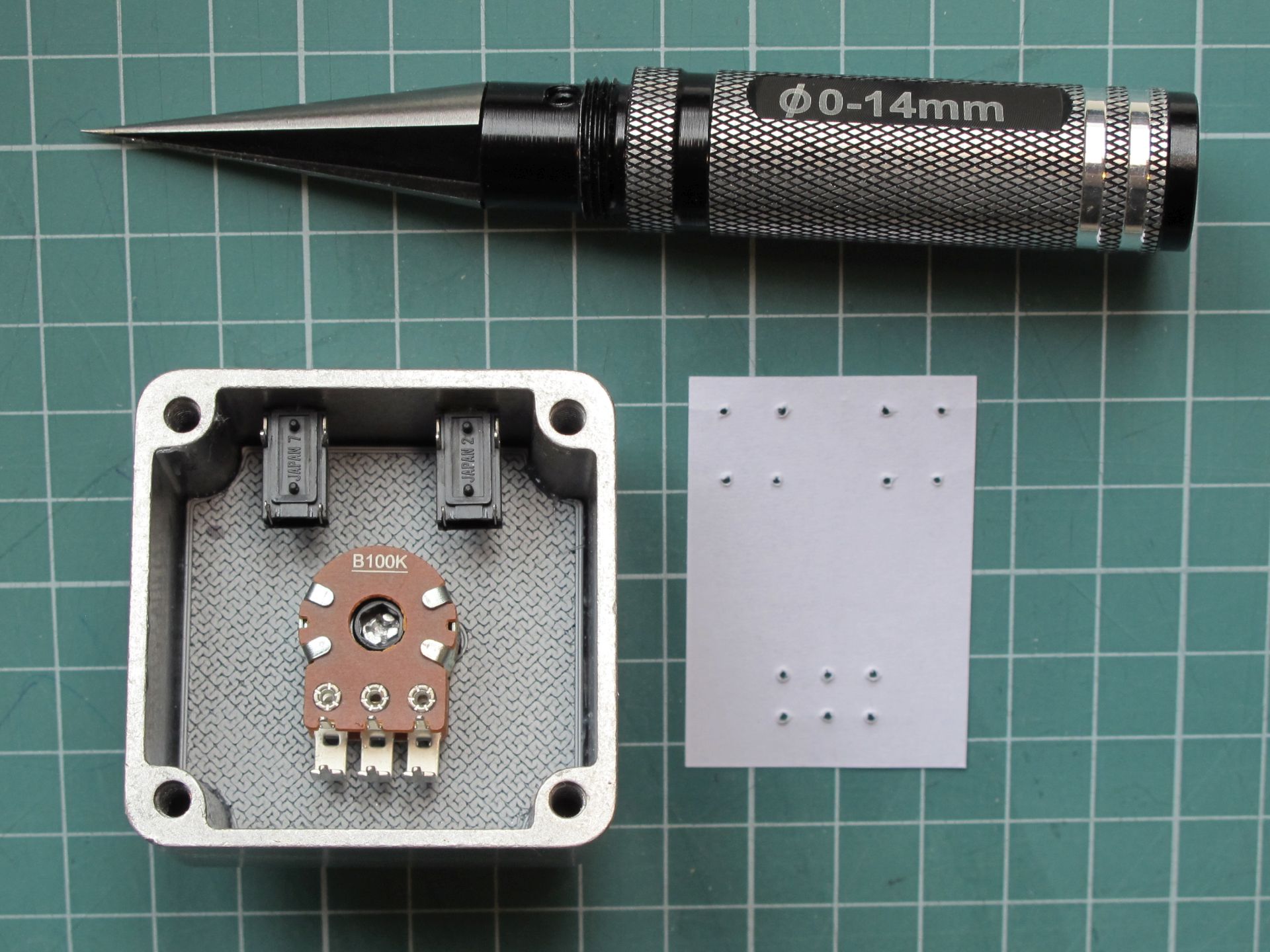
The best fitting one was chosen, I made holes inside the soldering pads and check placement one more time. The paper prototype just slip onto the terminals without any friction, which was my goal. You can find the tool I used for hole punching under “14 mm Black Professional Reaming Knife” (or similar) phrase on AliExpress. From the paper template I also got exact dimensions of the PCB.
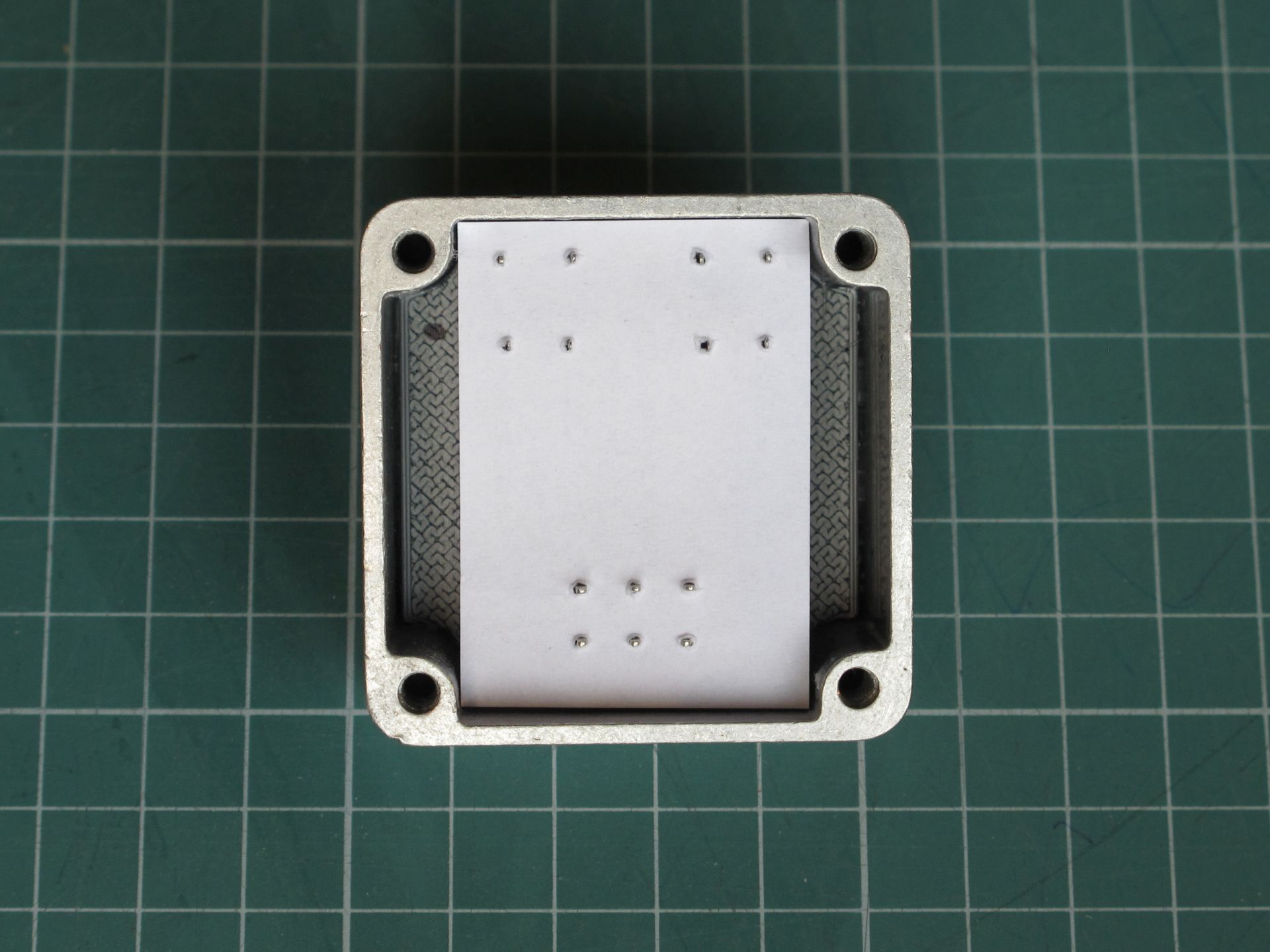
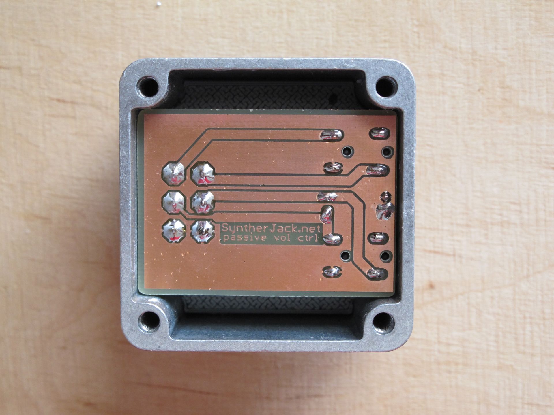
The PCB manufacturing took about 1 hour. As usual, I used photo positive method (Bungard laminate with light-sensitive coating + UV light exposing). I etched PCB slightly longer than planned, then ground it, to ensure very close fit on the side of case opposite to the sockets. It was important, as it prevented jacks from sliding out while pushing the plug in.
I was about to solder my passive volume control together, when thought came – the circuit is indeed very simple and I probably didn’t make any mistake, but what “if”? It would be really stupid to have an undemountable volume control with wrong direction of potentiometer rotation :/ Moreover, I made similar obvious mistakes in the past and I wasn’t going to repeat them.
The build – quick tests & final soldering
Because after soldering all parts together there was no easy way of disassembly them, I tested the circuit. Just copied the PCB electrical connections with protoboard and jack modules. As everything worked fine, I soldered the resistors sealing my passive volume control forever. FOREVER!
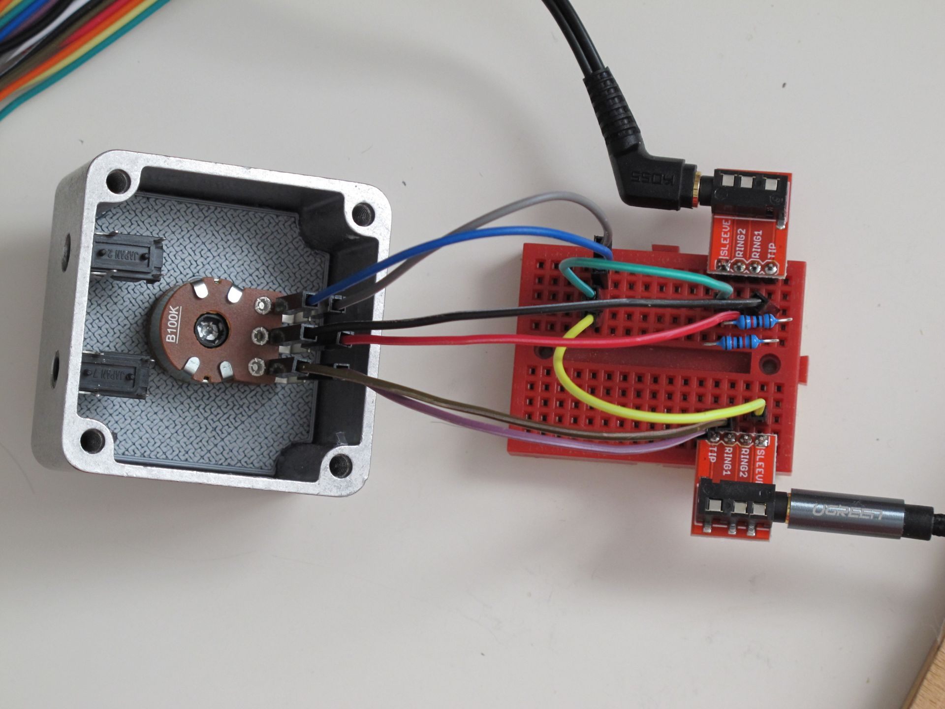
After 2 minute long tests I soldered the resistors to the PCB, then PCB onto the pot and jacks terminals. I know, board should be protected with some additional antyoxidation coating, but I intentionally missed this step. There was a chance, a lacquer will soak on the other side of PCB and stick to the opened jack sockets.
The big final!
Passive volume controls are quite expensive for what they are, usually just a dual audio taper pot with a pair of jacks or RCAs. The cheapest can be found for around 20 euros, more expensive cost hundreds. Mine below 10 euro, but it cost me a lot of time, more than I expected. I am very close to saying, I just unnecessarily wasted few days to get the knob recessed into the case. But at least it looks almost as good as I imagined 🙂
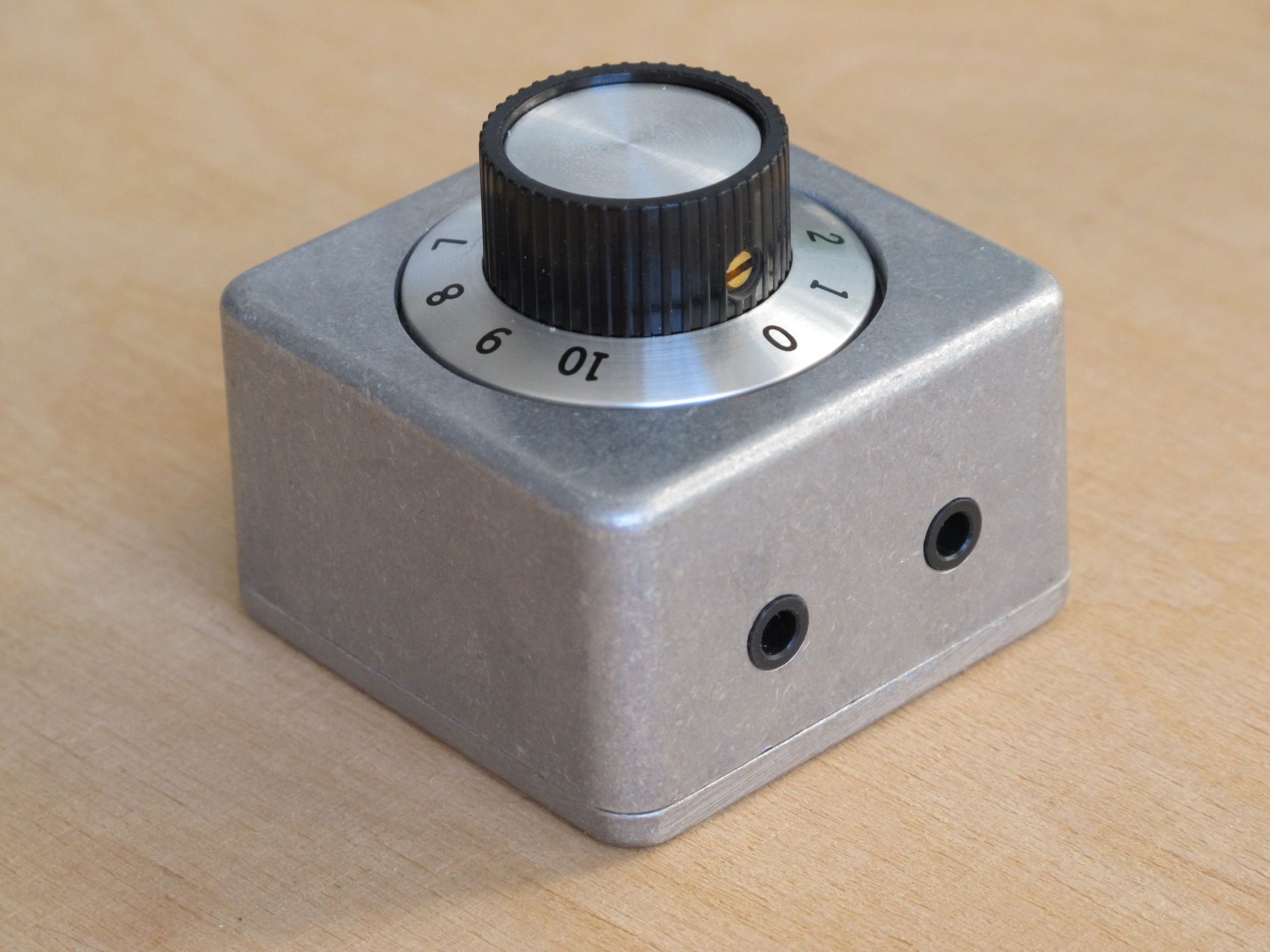
If you are wondering, where is the “0” position, it’s on the top, where jacks are. And the “input/output” marking are on the bottom on the case. Unit won’t be unplugged frequently anyway. The size of thr finished device is 50 x 50 x 45 mm and the weight 90 grams. The knob and rotation resistance feels classy.
I hope it was an interesting journey, which will inspire you in some amazing DIY projects!
Cheers
Jack
Glad you shared this despite its simplicity! The execution and design is great. Really love how the knob is set into the case. Makes for a really professional looking piece of gear. And yes – hard to beat the feel of a giant pot!
Looks neat!
I think I‘ll build something like that, just for the fun of it. I have an old footswitch-enclosire lying around, would be perfect for something like taht…
Sadly, I have only mono-jacks and moni-potentiometers lying around…
Hey syntherjack, does this volume control really work? Please excuse my doubts. There only based on the fact that I have yet to build one that works through the full range of travel as would the knob on my stereo. I even purchased one on two occasions and only created sound in the last 10%. No more than I could do. The best I could do was part of a small amp. I built. About the last 25% travel. I even read Elliotts lengthy report on the subject. What percent of travel do you create music. And your doing it with one pot and two resistors? All those grounds end up together and on your pcb. Just trying to understand exactly what you did.
Your friend Keith
Guten Tag
Kannst Du mir so ein Teil fertig – bauen ?
Gruss
BrunoKeiser
The impedance of your headphones should be quite high for this to work really well. What impedance are they?