Introduction
As Korg Volca Modular prices dropped recently to around 100 euro, it became a great and quite cheap introduction into the World of Voltage Controlled Modular Synthesizers. With additional Arduino and few components, you can ensure yourself many nights of modulation heaven (or hell, it all depends). So, how to connect Arduino to Volca Modular safely and throw some basic LFO? Let’s go straight to it!
The circuit
Long story short: I used Arduino Nano. First thing – Arduino outputs 0 – 5 V level signals, Volca Modular can receive safely 0 -3,3 V on all its inputs (in fact specs are not so tight, but lets stick to official data). Second thing, as Arduino outputs only digital signals, so we have to find a way to transform then into analog ones. The plan is as following:
- implement Pulse Width Modulation based waveform generation in Arduino, then smooth the output using simple lowpass filter,
- then add a simple voltage divider on Arduinos output to drop voltage from 5 V to around 3,3 V,
- as we don’t know what really happens on Volca Modular inputs, buffer the output to add protection to the Arduino.
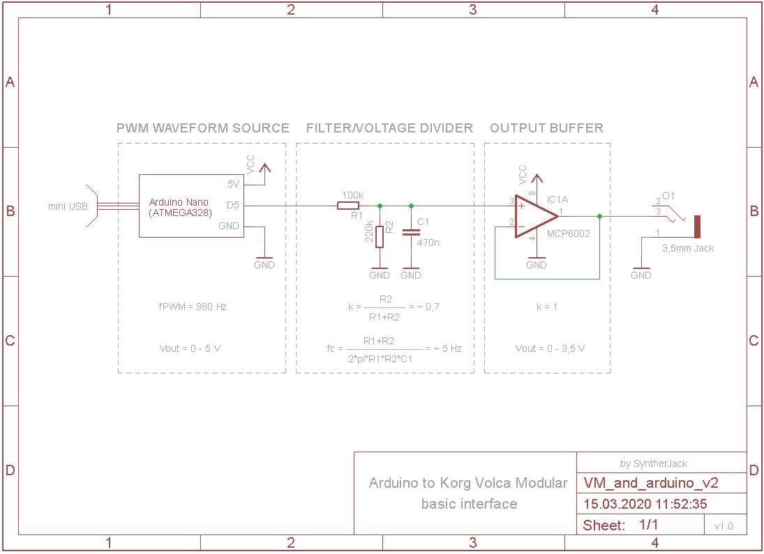
Filter/voltage divider
The circuit is a tradeoff between functionality and parts count. R1, R2 and C1 forms a voltage divider and passive RC lowpass filter. The amplification of this section is around 0,7 and cutoff frequency close to 5 Hz. 0,7 because we need to drop voltage from 5 V to 3,3 V (3,5 will do the job also). But where this 5 Hz came from?
Arduinos analogWrite PWM frequency (carrier signal frequency) is fixed and for Arduino Nano equal to 490 or 980 Hz depending on pinout choice. Higher PWM frequency allow us to output higher CV modulation signals, so pin 5 or 6 with 980 Hz capabilities seems an obvious choice. The rule of thumb says the filter cutoff should be 1000x lower then PWM frequency and it is a good starting point for cutoff frequency calculation. In general:
- the lower filters cutoff frequency will give us less distorted final modulation signal (lower peak-to-peak ripple voltage), but for the price of its lower maximum frequency (for LFOs it’s usually no big deal unless you want your LFO to go into audio range),
- the higher filters cutoff frequency, the more distorted signal, but you can go wild with outputs signal frequency (then call your device lo-fi or 8-bit and get $$$ for it).
You can use this great free online RC Lowpass Filter Design Tool for PWM to further explore the problem.
To get the R1, R2 and C1 I used formulas showed on schematic. For the designed simple RC filter, the peak-to-peak ripple voltage is around 0,03 V for 50% pulse width – in other words, when you set pulse width value in Arduino to 128, the output voltage after filter will be not constant, but slightly changing (+/- 0,015 V with 980 Hz) as carrier signal will not be filtered entirely. You can always make the circuit better by using more advanced active designs, like f.e. Sallen-Key I used in my Korg Monotron Duo LFO to get more aggressive fitering.
Output buffer
The last piece of the puzzle – output buffer build around MCP6002 rail-to-rail opamp. As we are not shure, how Volcas internal inputs looks like, it is safer to use an output buffer to protect our Arduino and separate LP filter from Volca Modular internals . Free advice: get some MCP6002, they are very handy for battery and USB powered synths.
The sketches
Generally speaking, there are 2 basic approaches to microcontroller based signal generation:
- using formula to generate signal values in real-time (great where you are able to form a formula describing your waveform – basic shapes like square, saw, triangle and random waveforms),
- reading stored (precalculated) values from lookup table (great for almost everything).
PWM signal generation itself is implemented with analogWrite() and delay() functions avaliable for Arduino platform. There are better ways to do this, like writing directly to ATmega Timer registers in carefully chosen PWM mode and using Timer overflow interrupts for precise timing, but you’ve got all that to come. In this short tutorial I will cover only basic waveform generation and give you four examples – all tested with Arduino Nano:
- sawtooth generation using basic formula, great as modulation source f.e. for pitch to get Dub Siren feel,
- 3 step waveform created with simple array, great for arpeggios,
- 4 step customizable waveform generation with if-else logic, perfect for slow stepped modulations,
- sine with 3rd harmonic using lookup tables as sample source, nice for slowly evolving drones.
Fell free to use the sketches and modify them as you wish, you can’t damage your Volca Modular in this way (at least in theory). In all sketches, delay() is responsible for output signal frequency. The higher delay value will be, the lower resulting frequency.
Example 1 – generation of sawtooth waveform using formula
Sawtooth waveform is most easy to generate. The only thing you have to do is just increment pulse_width and after it reaches its maximum value, reset it. For instance, in presented sketch ~1 Hz sawtooth is generated.
//Arduino Nano sawtooth LFO -> Volca Modular
//by SyntherJack, 14.03.2020
#define to_Volca 5
//pin 5 of Arduino Nano has 980Hz PWM frequency
//check yours here: https://www.arduino.cc/reference/en/language/functions/analog-io/analogwrite/
int pulse_width = 0;
int pulse_width_step = 1;
void setup() {
pinMode(to_Volca, OUTPUT); //configure as output
}
void loop() {
analogWrite(to_Volca, pulse_width); //generate PWM signal with PW defined by pulse_width
//change pulse_width for some modulation effect
//saw is one of the simplest to generate
//increment pulse_width until it reaches its maximum value (for 8-bit PWM it is 255, equal to 100% PW)
pulse_width = pulse_width + pulse_width_step;
//then reset it
if (pulse_width == 256){
pulse_width = 0;
}
//to get 1 Hz saw we need to increment pulse_width 255 times/second, which gives delay of around 4 ms
//but you can suit it to your needs (or add f.e. potentiometer to change it in real time)
delay(4);
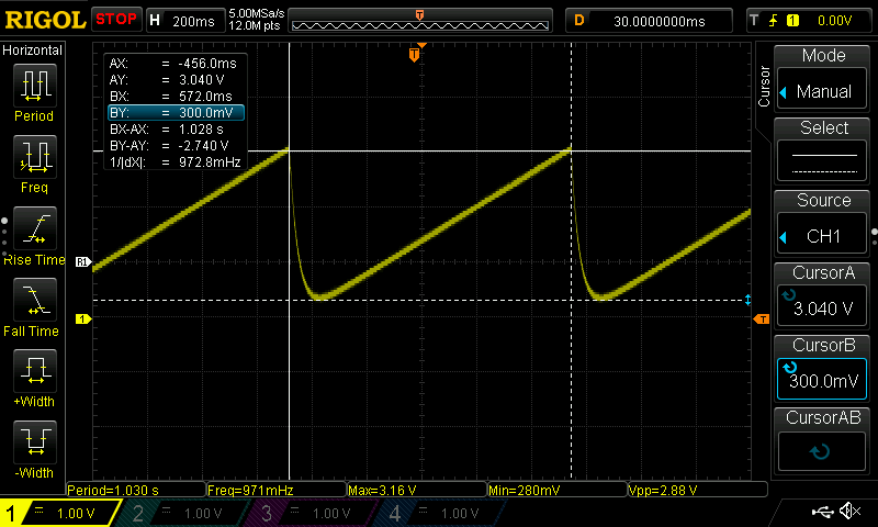
}And what the resulting waveform looks like (after the filter)? As you see, it is not a perfect saw, but at least it’s close to 1 Hz. Due to too low PWM frequency (and therefore low filter tuning) the slopes are not perfect. Now it is not a big problem, but with sequenced waveforms we will get compulsory slides between “notes”. We are also losing some of the waveform at the bottom (it should reach 0 V at the beginning of each cycle).
Example 2 – generation of a 3 step simple sequenced waveform
All the values are stored in STEP_VALUES[3] table. After time set by STEP_TIME passes the counter variable is incremented and new value is written into pulse_width variable. Unfortunately the PWM frequency is too low to create 8-bit style fast arpeggios. But if can live with a bit of distortion, you can for instance make the LP filters cutoff frequency higher by replacing 470nF by something like 220n (not tested) and go wild with C64 style music.
//Arduino Nano simple 3 step arpeggio -> Volca Modular
//by SyntherJack, 16.03.2020
#define to_Volca 5
//pin 5 of Arduino Nano has 980Hz PWM frequency
//check yours here: https://www.arduino.cc/reference/en/language/functions/analog-io/analogwrite/
int pulse_width = 0;
int counter = 0;
//step values stored in array - minimum value is 0, maximum 255
const int STEP_VALUES[3] = {0, 128, 192};
//time each step will be played in ms
const int STEP_TIME = 200;
void setup() {
pinMode(to_Volca, OUTPUT); //configure as output
}
void loop() {
analogWrite(to_Volca, pulse_width); //generate PWM signal with PW defined by pulse_width
//read from STEP_VALUES and set pulse_width
pulse_width = STEP_VALUES[counter];
//increment counter - incrementation by 1 = 100 ms
counter = counter + 1;
if (counter > 2) counter = 0;
//delay value defines for how log step value will be hold
delay(STEP_TIME);
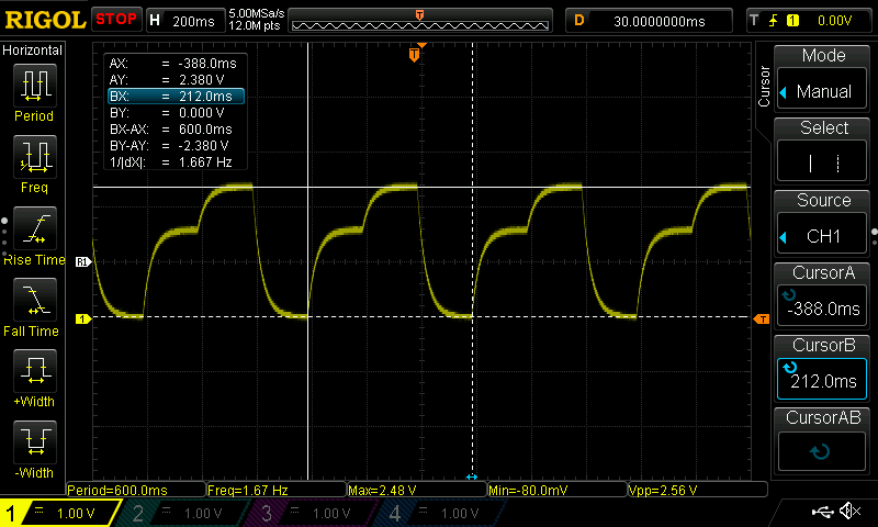
}The circuit output waveform looks as following. The slides between levels are not intended – as I mentioned before, the problem lays in too low PWM frequency and LP filter tuning. Of cource it can be solved by changing generated waveform frequency to lower 🙂 …or just moving to other waveforms generating techniques utilizing direct access to ATmega timers and interrupts.
Example 3 – generation of a 4 step customizable sequenced waveform
This code implements 4 step customizable sequencer. STEP_VAL_x is the value of the step in the range 0 – 255, and STEP_TIME_x tells when and for how long the STEP_VAL_x will be set. F.e. first step of the sequence will be at STEP_VAL_1 = 0 and held until counter reaches STEP_TIME_1 = 5. Step 1 will be played for 5 x delay time, equal to 5 x 100 ms = 500 ms. Then pulse_width will be changed to STEP_VAL_2 = 128 (around 1,7 V after the RC filter) until counter reaches STEP_TIME_2. This will take also 500 ms. Step 3 with STEP_VAL_3 = 192 will be played for around 1 second, then STEP_VAL_4 = 255 (around 3,5 V after the RC filter) for 500 ms and a whole sequence will end in 2,5 s after counter exeeds STEP_TIME_4. In addition, you can extend this logic for 8 steps or 16 steps, sky is the limit (in real synth DIY, the only limit is how much you can spend on potentiometers 🙂 )
//Arduino Nano simple 4 step sequencer -> Volca Modular
//by SyntherJack, 14.03.2020
#define to_Volca 5
//pin 5 of Arduino Nano has 980Hz PWM frequency
//check yours here: https://www.arduino.cc/reference/en/language/functions/analog-io/analogwrite/
int pulse_width = 0;
int counter = 0;
//step values - minimum is 0, maximum 255
const int STEP_VAL_1 = 64;
const int STEP_VAL_2 = 128;
const int STEP_VAL_3 = 192;
const int STEP_VAL_4 = 128;
//step switching time (in STEP_DUR_X x 100 ms)
//maximum step switching time is equal to 32,767 (for Arduino Nano int), and for 100 ms delay equal to around 55 minutes
const int STEP_TIME_1 = 5;
const int STEP_TIME_2 = 10;
const int STEP_TIME_3 = 20;
const int STEP_TIME_4 = 25;
void setup() {
pinMode(to_Volca, OUTPUT); //configure as output
}
void loop() {
analogWrite(to_Volca, pulse_width); //generate PWM signal with PW defined by pulse_width
//increment counter - incrementation by 1 = 100 ms
counter = counter + 1;
//change pulse_width for some modulation effect
//stepped waveform can be used to define a somehow musical sequence
if (counter <= STEP_TIME_1) pulse_width = STEP_VAL_1;
else if (counter > STEP_TIME_1 and counter <= STEP_TIME_2) pulse_width = STEP_VAL_2;
else if (counter > STEP_TIME_2 and counter <= STEP_TIME_3) pulse_width = STEP_VAL_3;
else if (counter > STEP_TIME_3 and counter <= STEP_TIME_4) pulse_width = STEP_VAL_4;
else if (counter > STEP_TIME_4) counter = 0;
//delay value defines timing step - here is equal to 100 ms
//lower values will give you faster sequence
delay(100);
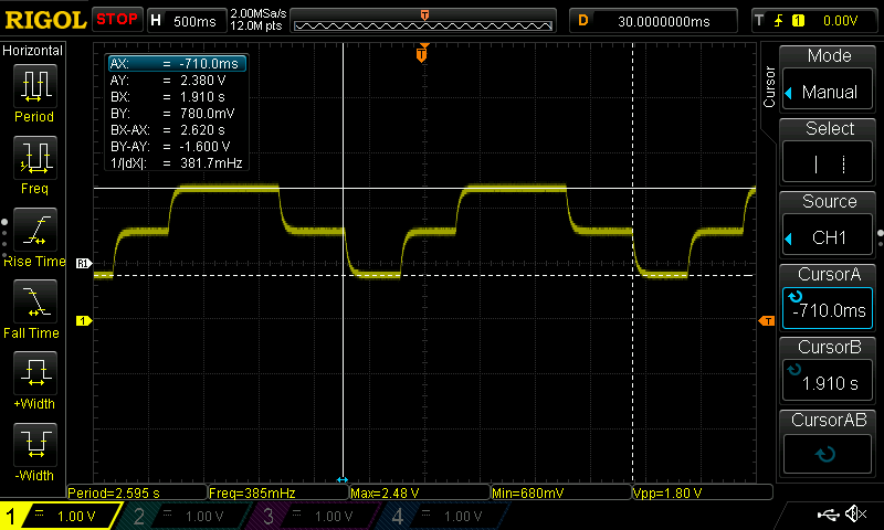
}Now, much slower waveform is generated then in previous example. The period of a waveform is close to to 25 x 100 ms = 2,5 s, as we expected. The offset ~680 mV offset is intended – the lowest value of STEP_VAL is 64 (1/4 of maximum possible output voltage). To get any musical result, the waveform should be rescaled in Volcas utility module to hit the notes.
Example 4 – generation of a sine waveform with 3rd harmonic using lookup table
Lookups are my favourite – fast, you can generate any waveform you will imagine – memory size is the only limitation. I used this technique in my Monotron DUO to add an LFO, in Simmons SDSV hi-hat expander for metallic waveform generation and in Manutronix Dub Siren for LFO with customizable waveshape. The only thing you have to do is to read the consecutive table values and output them. The problem is – how to get the table values? Stay tuned for the tutorial on lookup table creation!
//Arduino Nano sine with 3rd harmonic LFO -> Volca Modular
//by SyntherJack, 14.03.2020
#define to_Volca 5
//pin 5 of Arduino Nano has 980Hz PWM frequency
//check yours here: https://www.arduino.cc/reference/en/language/functions/analog-io/analogwrite/
int pulse_width = 0;
int counter = 0;
//lookup table with stored waveform walues - here a sine with 3rd harmonic
int sine_with_3_harm[256] = {0xFE, 0xFE, 0xFE, 0xFD, 0xFB, 0xFA, 0xF7, 0xF5, 0xF3, 0xF0, 0xEB, 0xE8, 0xE4, 0xE0, 0xDC, 0xD7,
0xD1, 0xCD, 0xC7, 0xC3, 0xBD, 0xB8, 0xB2, 0xAE, 0xA8, 0xA2, 0x9C, 0x97, 0x92, 0x8C, 0x88, 0x84,
0x80, 0x7B, 0x77, 0x73, 0x70, 0x6B, 0x68, 0x66, 0x64, 0x61, 0x60, 0x5E, 0x5D, 0x5D, 0x5C, 0x5C,
0x5D, 0x5D, 0x5D, 0x5E, 0x60, 0x61, 0x64, 0x66, 0x68, 0x6A, 0x6D, 0x70, 0x73, 0x75, 0x78, 0x7B,
0x7E, 0x82, 0x85, 0x88, 0x8B, 0x8E, 0x91, 0x94, 0x95, 0x98, 0x99, 0x9C, 0x9E, 0x9F, 0xA1, 0xA1,
0xA1, 0xA2, 0xA2, 0xA1, 0xA1, 0x9F, 0x9E, 0x9C, 0x99, 0x98, 0x95, 0x92, 0x8E, 0x8B, 0x87, 0x84,
0x80, 0x7A, 0x75, 0x71, 0x6B, 0x67, 0x61, 0x5C, 0x56, 0x51, 0x4C, 0x46, 0x40, 0x3A, 0x36, 0x30,
0x2C, 0x26, 0x22, 0x1E, 0x19, 0x15, 0x12, 0x0E, 0x0B, 0x08, 0x07, 0x04, 0x02, 0x01, 0x00, 0x00,
0x00, 0x00, 0x00, 0x01, 0x02, 0x04, 0x07, 0x08, 0x0B, 0x0E, 0x12, 0x15, 0x19, 0x1E, 0x22, 0x26,
0x2C, 0x30, 0x36, 0x3A, 0x40, 0x46, 0x4C, 0x50, 0x56, 0x5C, 0x61, 0x67, 0x6B, 0x71, 0x75, 0x7A,
0x7E, 0x82, 0x87, 0x8B, 0x8E, 0x92, 0x95, 0x98, 0x99, 0x9C, 0x9E, 0x9F, 0xA1, 0xA1, 0xA2, 0xA2,
0xA1, 0xA1, 0xA1, 0x9F, 0x9E, 0x9C, 0x99, 0x98, 0x95, 0x94, 0x91, 0x8E, 0x8B, 0x88, 0x85, 0x82,
0x7E, 0x7B, 0x78, 0x75, 0x73, 0x70, 0x6D, 0x6A, 0x68, 0x66, 0x64, 0x61, 0x60, 0x5E, 0x5D, 0x5D,
0x5D, 0x5C, 0x5C, 0x5D, 0x5D, 0x5E, 0x60, 0x61, 0x64, 0x66, 0x68, 0x6B, 0x70, 0x73, 0x77, 0x7A,
0x7E, 0x84, 0x88, 0x8C, 0x92, 0x97, 0x9C, 0xA2, 0xA8, 0xAC, 0xB2, 0xB8, 0xBD, 0xC3, 0xC7, 0xCD,
0xD1, 0xD7, 0xDC, 0xE0, 0xE4, 0xE8, 0xEB, 0xF0, 0xF3, 0xF5, 0xF7, 0xFA, 0xFB, 0xFD, 0xFE, 0xFE};
void setup() {
pinMode(to_Volca, OUTPUT); //configure as output
}
void loop() {
analogWrite(to_Volca, pulse_width); //generate PWM signal with PW defined by pulse_width
//set pulse_width using lookup table
pulse_width = sine_with_3_harm[counter];
//increment counter - incrementation by 1 = 4 ms, defined by delay
counter = counter + 1;
//maximum value for counter is 255 as it is the last index of a sine_with_3_harm array
if (counter == 256) counter = 0;
//if we want f.e. 0,125 Hz waveform (1 cycle every 8 seconds, or 8000 ms), the delay would be 8000 / 256 = ~31 ms
delay(31);
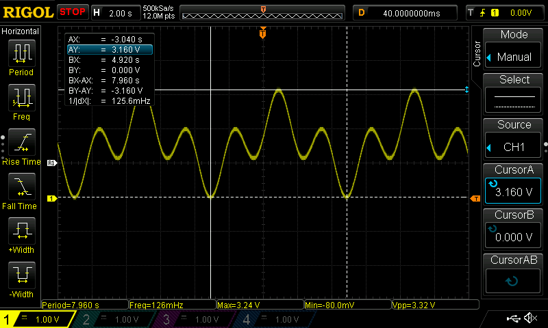
}We hit a 0,125 Hz frequency quite good, the waveform itself looks not distorted – at least not as much as previously generated. The base frequency is equal to 0,125 Hz and third harmonic 0,375 Hz – we are far away from filters cutoff frequency which is set to 5 Hz. As we used a lookup table, just by switching it we can generate (almost) every imaginable waveshape!
Let’s put it all together!
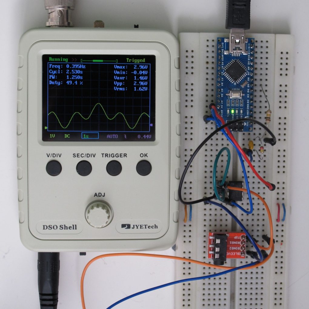
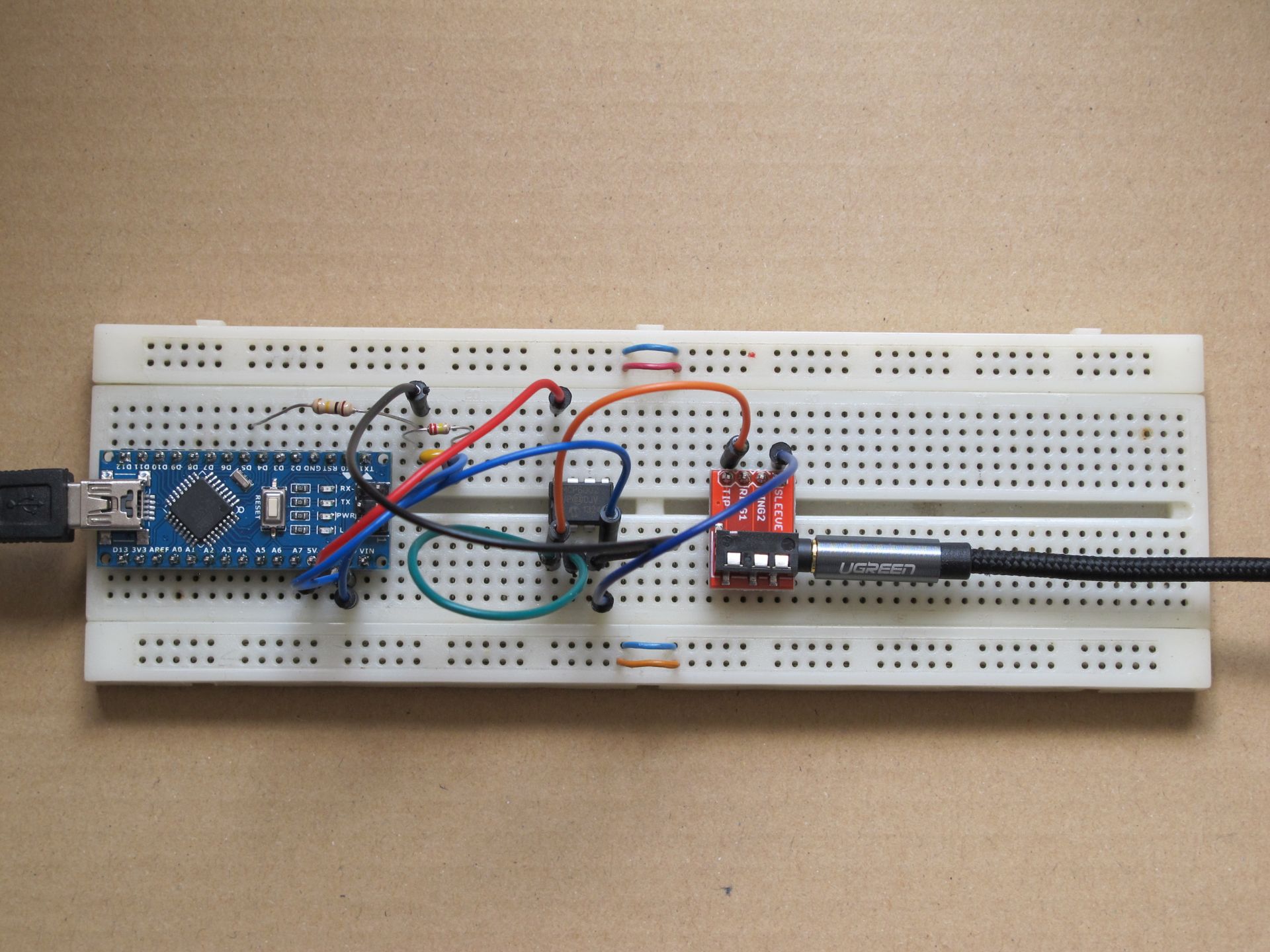
Actually, there is not much to put together. As you can see, I connected my Arduino Nano via mini USB to supply the circuit. D5 is the PWM output from the Arduino and 3 visible passive elements create the filter/voltage divider. Output buffer is supplied from Arduinos PCB (pins 5V and GND). In addition I used a Mini Jack break out board to simplify the connection to Volca Modular (Jack inputs and outputs are the only points you can reach Volcas ground). And thats it!
I created a basic raw demo to show possibilites of using Arduino as modulation source. I will leave the whole creative/musical process up to you, as I suck at music production. I used all the sketches presented above, so you can easily replicate the results. Moreover, you can try to generate two waveforms at a time, one 980 Hz pin on Arduino Nano is still free!
Remember, you use all my sketches and ideas on your own responsibility. Don’t send me broken Volcas 🙂
Happy DIYing and stay tuned!
Cheers,
Jack
Great stuff!! Have you considered using an Arduino MKR Zero? From what I understand, it outputs 3.3V and has one analogue output (as well as 7 analogue inputs), so it could perhaps be patched directly into the Volca Modular. I still did not have the time to go after this, but I was thinking of creating extra modules for my Volca Modular using multiple circuits of this model of Arduino, patching them between each other and directly into the Volca using jumper wires.
Man, would it be possible to make an arduino circuit for a clock divider-multiplier? I would like to add it to my volca mix.
It would be a great little project!
Also the Volca modular clock put is not directly compatible for to be used as sync for other volcas, it needs a sort of littlebits-pulse converter for to be able to use the modular clock divider out for syncing other volcas, I do not know if you noticed that.!
The Midi out send a pure Midi-clock, that can be used to convert the normal sync, to a full fledged Midi-clock, super stable. No notes, nothing, just the clock out from the PIN used for Midi out…
I use it a lot to sync all the Volcas to other gear, when I want to set the Volca as Master clock.
I didn’t do anything special also, no circuitry, just a normal TRS jack.
I have a Tangible Waves clock divider, and it works flawlessly with the V. Modular analogue clock out pulses…
Look at AEM Modular system, it costs a fraction of Eurorack modules, and the also have a Volca Modular converter module,
I don’t have that and everything works fine in both directions.
littlebit-pulse are biased signals, you’ll need to amplify and clip it to ground, it’s a really simple circuit, no IC’s involved.
Did you know of the Korg Modular EURO project? There was a facebook page, they made into a small production with patreon I think, it was a full Volca Modular to Eurorack conversion kit, with extruded pins in the internal side, normalled to minijacks.
It’s become impossible to find about the makers or the project itself anymore.
Even this page, was rather difficult to find. Props.