When I first saw Korg Monotron Duo in 2014, I thougth: “Nothing to do here”. Mod points were quite boring, even with schematics there was not a lot to do. With Original Monotron, or even Delay, there were some exciting and very simple hacks. So I bought a Monotron Delay, modded it and forgot about his blue brother.
The idea
Few weeks ago I was cleaning my hard drive and saw Duo schematics by accident. Mod points were still boring, but I found some other interesting things I didn’t think about before:
- SQR1 and SQR2 – if there’s a square, there is a suboscillator (very easy to make with microcontroller external interrupt acting as frequency divider),
- SAW1 and SAW2 – sawtooth = PWM, also can be used as second VCO waveform,
- PLS1 and PLS2 – can be used as clock for some waveform generation,
- GATE – LFO reset, as in Original Monotron,
- IC5A pin 2 – VCF cutoff CV can be injected here,
- Q1 and Q3 base – VCO pitch CV injection point.
Now the problem was how to put it inside Monotron along with all pots and switches. From my small experience with Delay I knew I could fit: 2 pots and 4 switches or 2 pots, 2 switches and 1 pushbutton. I wanted an LFO with frequency and modulation depth control, so only option one left. I had to skip a lot of cool ideas 🙁 Finally I decided to add an LFO, suboscillator and a second waveform for one of VCOs.
The measurements
I have connected wires to all Monotrons mod points and checked the waveforms with oscilloscope. Squarewaves are 50% and come from GND to near VCC, sawtooths unfortunately have low amplitude (1, 12 V) with very uncomfortable 2,86 V offset.
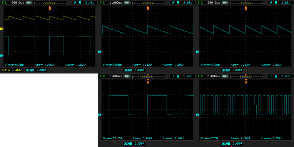
VCO2 squarewave amplitude is slightly lower due to additional modulation circuit around Q3.

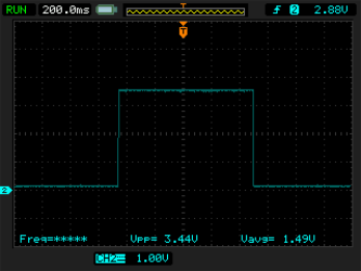
GATE signal goes from GND to about 3,44 V as long as ribbon keyboard is pushed.
So. The square is just begging to be used with microcontroller, sawtooth needs to be scaled (amplification with negative offset).
The circuit
I ended with following circit.
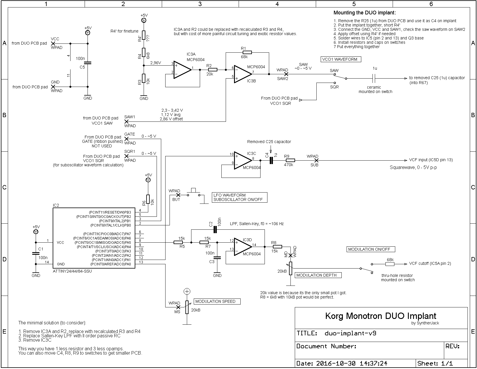
The upper circuit scales the SAW1 waveform – amplifies it and adds negative offset. Lower is based on Atmel ATTINY44 microcontroller and adds LFO and suboscillator. Microcontroller runs on internal 8MHz clock generator, software is slightly below 4 kB. I used this specific uC because of quite small (and easy to solder) SOIC14 package and build-in ADC. Opamp is Microchip MCP6004, cheap and rail-to-rail. Digital to analog conversion is done via 8-bit PWM. Sallen-Key II-nd order 120 Hz lowpass filter removes PWM carrier (cutoff frequency seems a little low but is ok for LFO).
The values of the pots (20 kB) were chosen by the lady in the electronic shop – it was the only “walkman type” pots she had. For other values you have to recalculate R8 (for 10 kB it will be 6k8). The R4′ resistor is to tune the sawtooth waveform offset – it has a value between 0 and 1k Ohm and should be soldered after installing PCB inside Monotron (there is a description on the schematics).
The software
Most waveforms generation is based on DDS, the random ones uses 16-bit LFSR (Linear Feedback Shift Register). One cycle of each non-random waveform are stored in 8 bit x 256 table (I store saw shapes also, but they could be computed as well).
There are 13 waveforms generated (12 of them are presented below). All goes from 0,25 to 20 Hz.
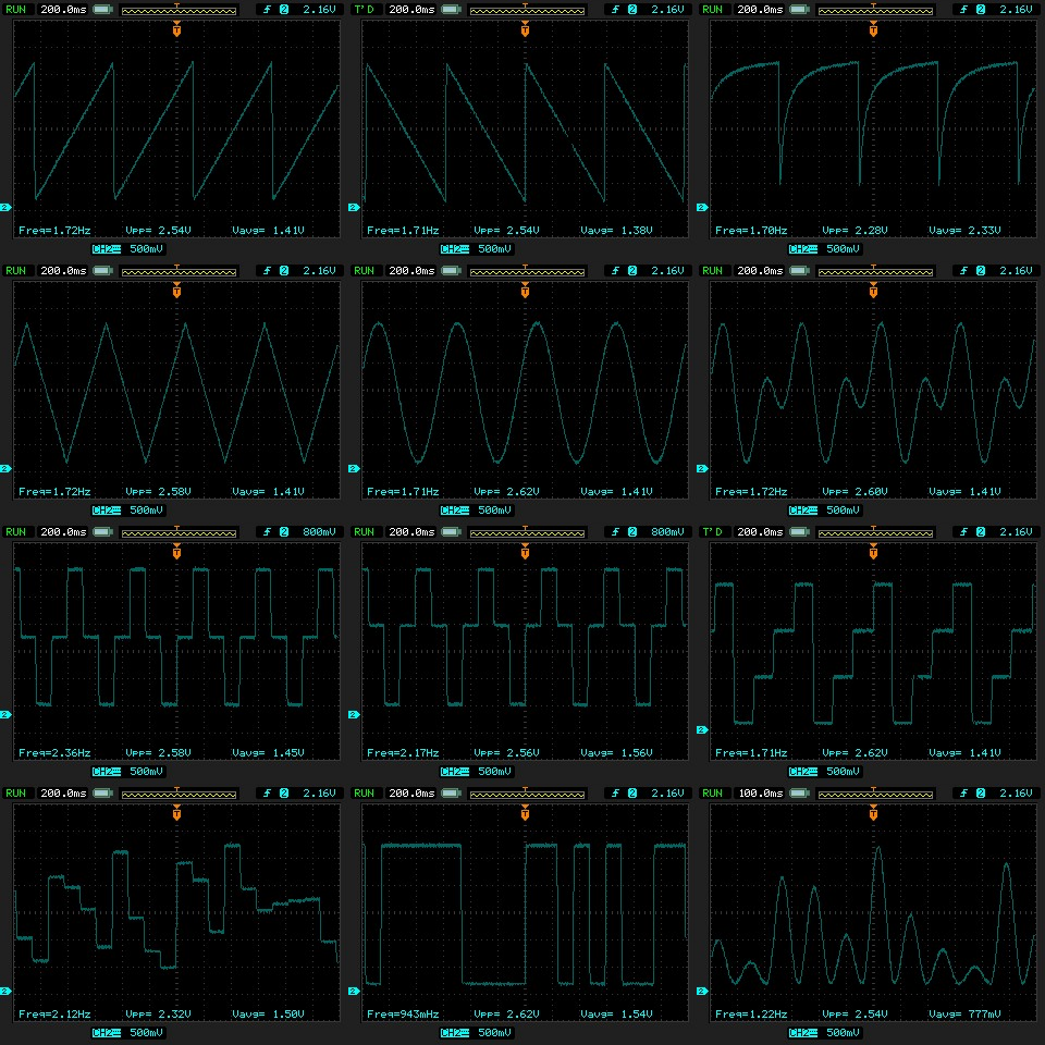
They can be divided into categories:
- standard – positive and negative saw, sine, triangle,
- special – expotential (for drum sounds), sine with 3rd and 5th harmonic,
- sequencer-style – 3 stepped in the third row,
- random – sample and hold, 1-bit noise and sine with random amplitude.
Suboscillator uses external INT0 interrupt to detect the positive squarewave edge from SQR1 point on Monotrons PCB. On each detection the suboscillator output is negated – this way SQR1 waveform frequecy is divided by 2.
The code has about 500 lines (mostly tables) and compiles to 4038 bytes. Ready to burn HEX file is at the end of the post in supermodderpackage.
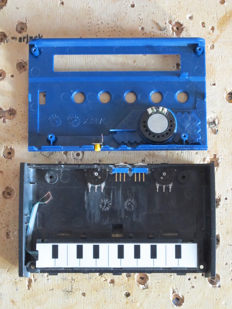
The build
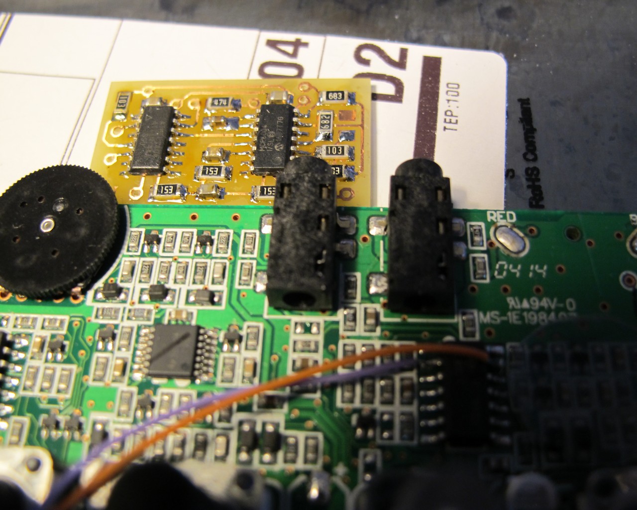
The idea was first tested on prototype board with thru-hole components, then moved to etched on-sided PCB with SMD parts.
The final SMD PCB is about 18 x 32 mm, it is a problem to fit something bigger inside Monotron. All resistors are on 1206 package and caps in 0805. The ready-to-print PCB as pdf can be found as attachment zipped at the end of post.
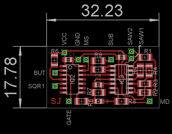
The PCB is really easy to solder with some soldering flux. Even without advanced SMD skills it should be a pleasure 🙂
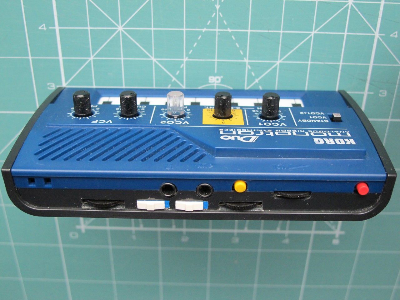
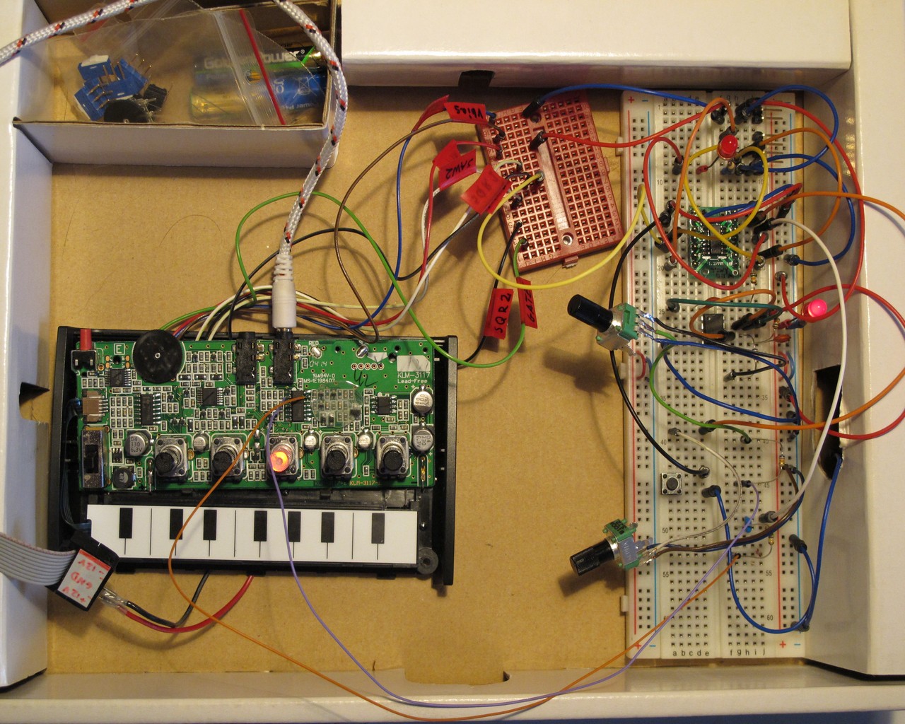
PCB is ready, now the drilling and filing. The pots are some unknown “walkman type”, switches Excel Cell Electronics ESP1010 and pushbutton Omron B3F-1062. All are glued with Autoweld CX-80. From inside it looks awful. Pots and slide switches fits under PCB and are only 2,5 mm high.
The only Monotron PCB mod points used are SQR1 (for suboscillator), SAW1 (as second VCO1 waveform), VCC and GND (for microcontroller and opamp supply). For wiring I used kynar.
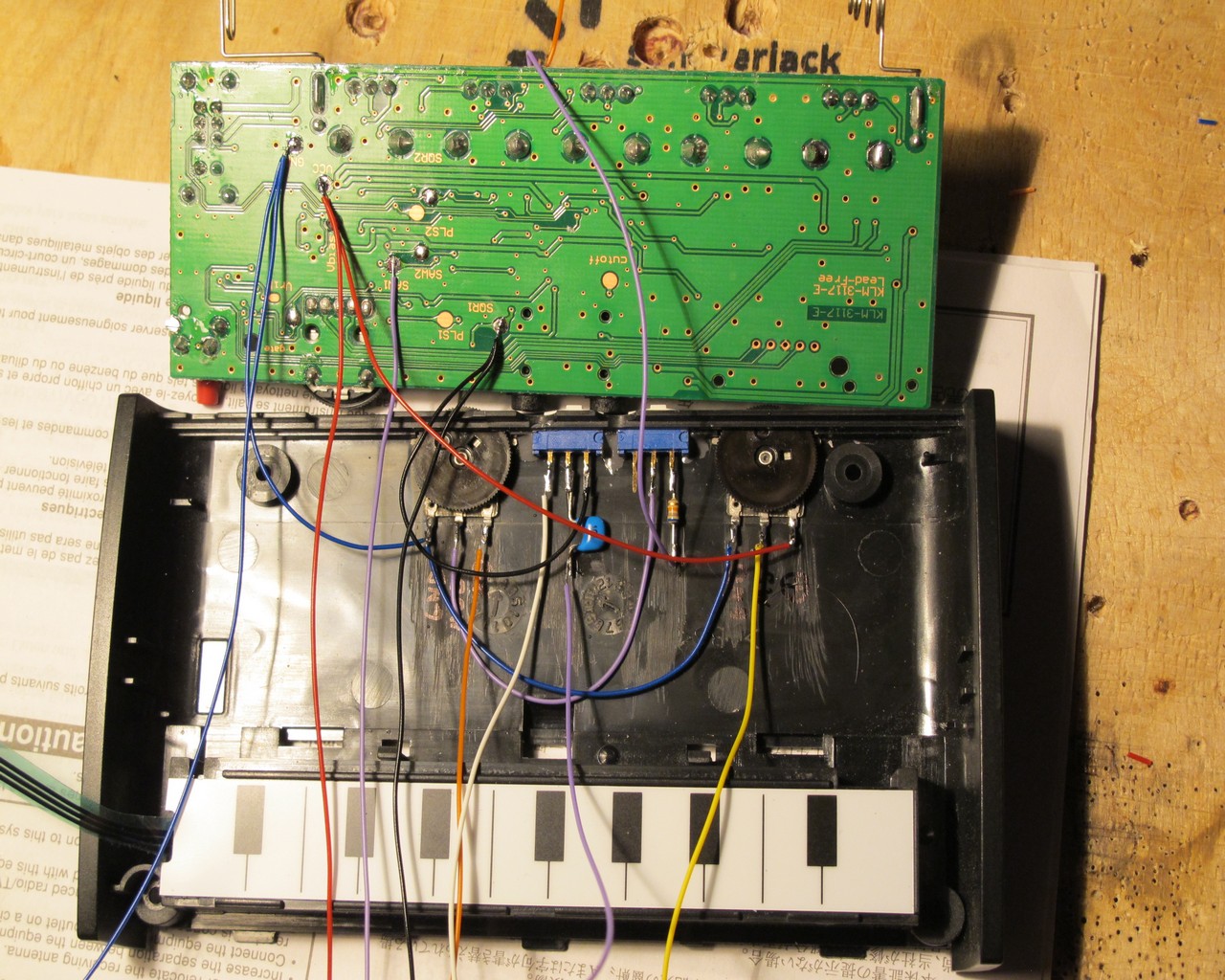
The implant PCB holds on thin transparent laser printer foil to keep it in place and protect againt shortcuts (wires are connected thru-hole).
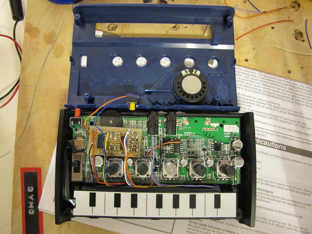
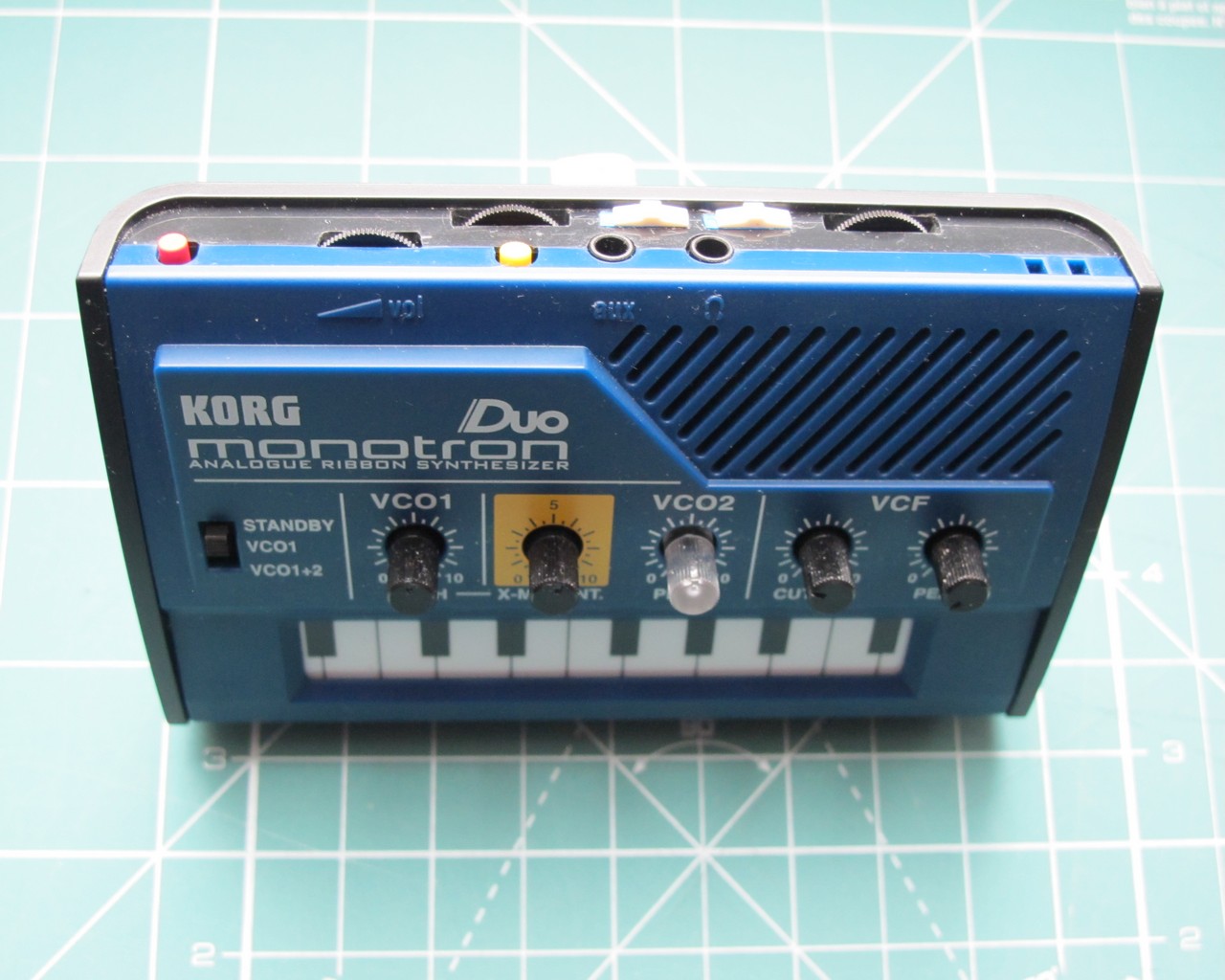
After resoldering speaker wires and closing the device, everything looks perfect. This is how Monotron DUO should be from the beginning. Slide switches may seem to close to the jacks, but they are just fine.
The demo
How it sounds? I don’t want to say it is impressive, but compared to stock device it can really make some amazing things. The demo is short and shows only few LFO waveforms.
Do all mods for your own responsibility. You may finish with dead or amazing device. The choice is yours.
Hi,
Are you planning to repeat the project? You could modify Monotron Duo devices, and sell them on ebay. I would be a buyer.
Please let me know if you are willing to buy a new device and mod it for me.
Cheers,
Attila
I spend over 20 hours to put this one together (not counting programming, etching etc.). It would be >400$ it I would sell one :/
Thanks for your response, that is too much indeed. Anyway, congratulations, keep up making cool devices.
hi,
what kind of pot or trim (i don´t know) i´d need for remplacing or reparing the “peak” function of my monotron duo?
i love your mod little machine!!
Cheers!
Reply
Hello,
from official schematics it looks like 10kB, Alps RK09 (but Alpha Taiwan may also fit)
Cheers!
Great work!
What other cool mods did you have to skip?
I’m currently awaiting my duo which is in the mail. Plan is to mod it with Teensy 3.2 as micro controller and re-house it.
Very inspiring!
Hello!
The problem was a limited space and I want to fit all controls on the back. I had idea to add PWM, as both generators output sawtooth waves, but it would need some additional switch (or potentiometer) to turn PWM off and on. The noise source would be also very useful for wind / snare style sounds, but still, one more pot for amplitude control. And a pulse generator, so you can excite filter at high resonance settings! With microcontrollers sky is the limit 🙂
Cheers!
Hi I know this is an old post but not long ago bought a monotone duo, and was disappointed to find the only the filter worked for the aux in.
I am wishing to modify it so that the aux in works with the VCOs.
I have seen a youtube video where a guy has modded the monotone delay in this way with one wire and a switch between the cutoff and LFO contacts.
The duo though has a different PCB layout so was wondering if you knew how this could be done.
I have been searching for any other posts about this mod but cant seem to find any as all other mods are more complex.
I would appreciate ideas or advice that you could give please.
Nice mod by the way.
I’m not shure what do you mean by “to modify it so that the aux in works with the VCOs.” You wish to change filters cutoff with aux in signal?
I’m currently attempting to modify my Monotron Duo so that I can control via CV (using a KMI QuNexus keyboard or a Beatstep/Pro). There seem to be lots of examples of people doing this with Original or Delay models but I’m struggling to find the relevant information about the Duo. I tried to understand it from your solder points but I’m not experienced/confident enough with soldering to contemplate attaching wires to the SMD components. Is it possible to do it using only the connections on the reverse of the board?
Hi, i really like this mod, so i decided to repeat it. I feel that i missed something. On your schematic you wrote “solder wires to q3 base”, but there are no details except common picture with mod points. Should i cut sqr2 trace as you showed on the picture, or it’s not needed for this mod? By now i have the following results: i got dirty saw signal on Saw2 output, saw and square switch works, i hear different waveforms, mod switch works, mod depth works, but i can’t understand why lfo doesn’t work or how to change it’s waveform. Suboscillator works, it is enabled and disabled with button. I have crappy 20MHz oscilloscope, please give me some tips how to find the issue.
Aaaaand i fixed it. I knew i screwed up somewhere, yes, my bad. I confused walkman pot pinout, because i have 5 pin pots. So, if you look at the knob, you need pins 1,2, 5. So easy, but spent so much time checking everything :).
It works! Thank you for both duo and delay, they are beasts!