4sum is a simple, monophonic portable audio mixer with 4 inputs and 1 output with separated level controls for each channel. I designed this one for one reason: I did not have any mixer for my Monotrons and other “toys”! (Now you can get it at patch.audio).
The design
The best way to design something good is to make a list of features you need, then check other designers failures, straighten or avoid them and add/review your own ideas – especially if we talk about something so popular and manufactured in thousands different variants like audio mixer. At first I’ve read a lot of small mixers reviews and wrote down other people complains. Among others, the most often repeated:
- poor battery life or no battery option,
- low quality potentiometers,
- output 180° phase shifted (which in some setups caused signal to cancel),
- mono output for mono mixers (only one speaker plays after you connect mixer to amplifier).
Then I’ve added my own thoughts and experiences:
- OUTPUT level control – “Who is playing loud on those damn Monotrons! Turn down the volume!” – very usefull on synth meets if you don’t want to run every 10 minutes to main mixing console,
- no channel MUTE if it can’t be done right (without loud pop sound) – I’ve got kicked out from one synth meet for this :/ So, pop generation chance should reduced to minimum,
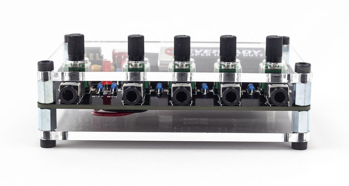
- all connectors on top to avoid unnecessary mess with cables going on different sides of device,
- power supply from 9F22 batteries – quite cheap, popular, gives plenty of headroom and you can buy at as USB rechargeable!
The circuit
…is simple and effective. Signal is coming via one of four INPUTs and its level is set by LVLI1..LVLI4 potentiometers. R1..R4 are mixing resistors, C1 is removing DC on the IC1A input. IC1A and IC1B are cofigured as inverting amplifiers one with the constatant gain of one and second dependent on LVLO setting. Two inverting amplifiers connected in series will cause input and output signals to be in phase. R6 resistor along with LVLO potentiometer sets mixer amplification, from 0 to around 2. C2 with R7 acts as lowpass filter, removing DC component from the output. TLo72 is protected against shortcut, so no additional output resistor is needed. Biasing circuit is a standard voltage divider (R8 and R9) with C4 as potential supply noise remover. R10 and LED serves as circuit power indicator and D1 protects is against negative battery connection.
The circuits heart is build around TL072 low-noise operational amplifier (obvious choice in many audio-related circuits). I just cannot justify use NE5532 opamp in portable application, less noisy, but 3x more power hungry. You can use it if you want, but device operation time will drop significantly (see tests below).
The choice of 2x amplification ensure there will be no clipping for consumer (~0,9 Vp-p) audio level – slight clipping can be hearable for professional (~3,5 Vp-p) audio level and maximum amplification. Unfortunately mixer will not handle eurorack hot signals around 10 Vp-p. 6F22 battery power supply for consumer audio level gives a headroom ~2,4 V ((5,6-0,9)/2), for professional ~1,1 V ((5,6-3,5)/2), which will drop as battery became to discharge (see tests below).
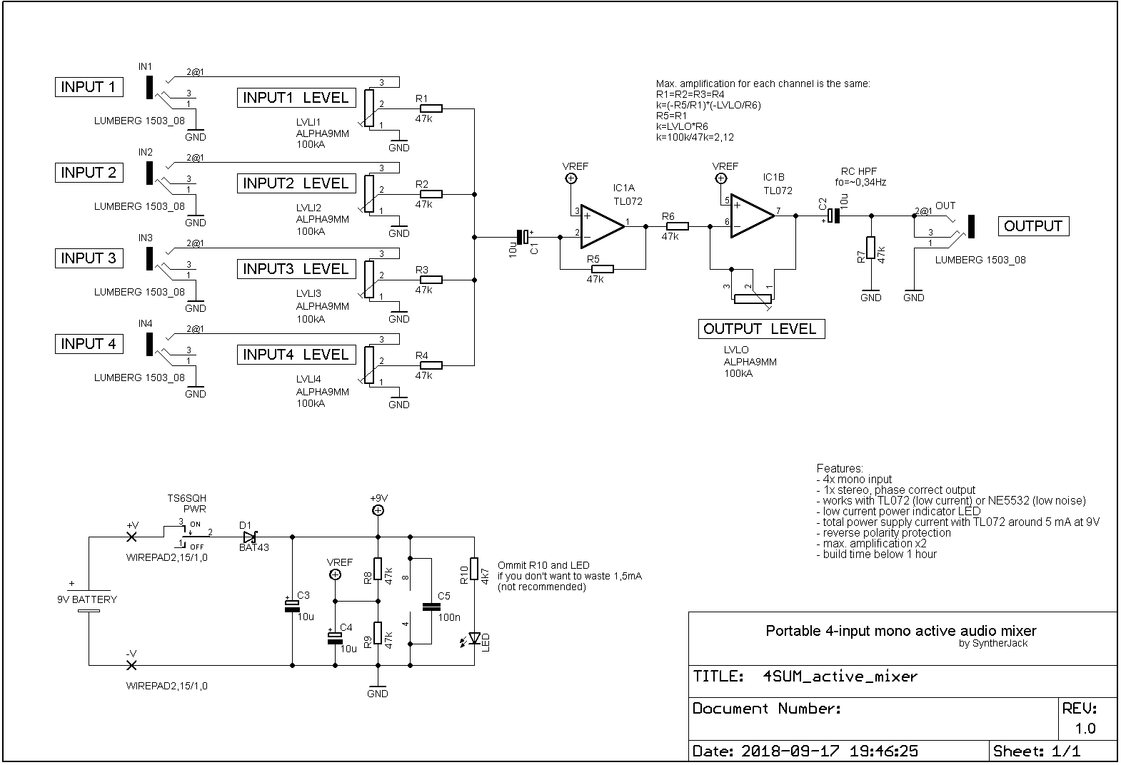
One may say, output jack connection is oversimplified – two output pins (jacks tip and ring) are just shorted. The only negative effect is, if you plug mono cable (with ring and sleve connected), the mixers output is grounded (so there is no output signal). Opamp output is shorted to ground via C2, but thanks to protection IC survives 🙂 This could be solved more elegant way with output buffer, but then supply current would double. So the only real disadvantage is you have to remember to use stereo-stereo or stereo-RCA cable to interface the device you feed mixers output signal into.
The PCB
PCB size is 93×60 mm and was mostly defined by comfortable distance between potentiometer centers (16 mm). There are not many components but I’ve tried to place them in a way that no additional description is needed. The unusual battery holder (I am very proud of) is build into PCB and takes advantage from devices “sandwich” design.
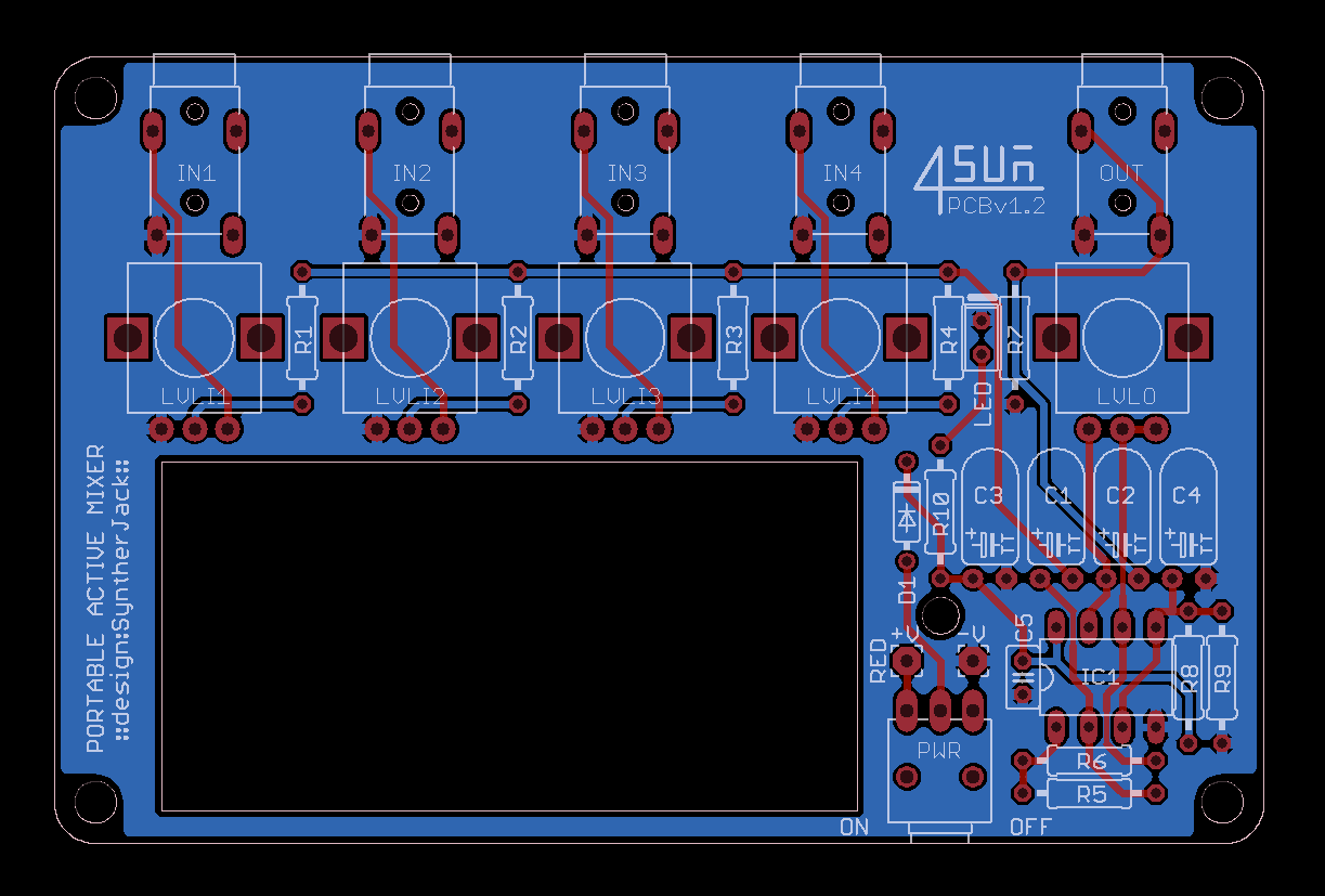
I’ve fabricated 3 versions of the PCB: v0,98, v1,0 and v1,2, they differ from each other only in hole and captions placement. First two prototypes were manufactured at EleCrow, the final one at PCBWay. In both cases the quality was great.
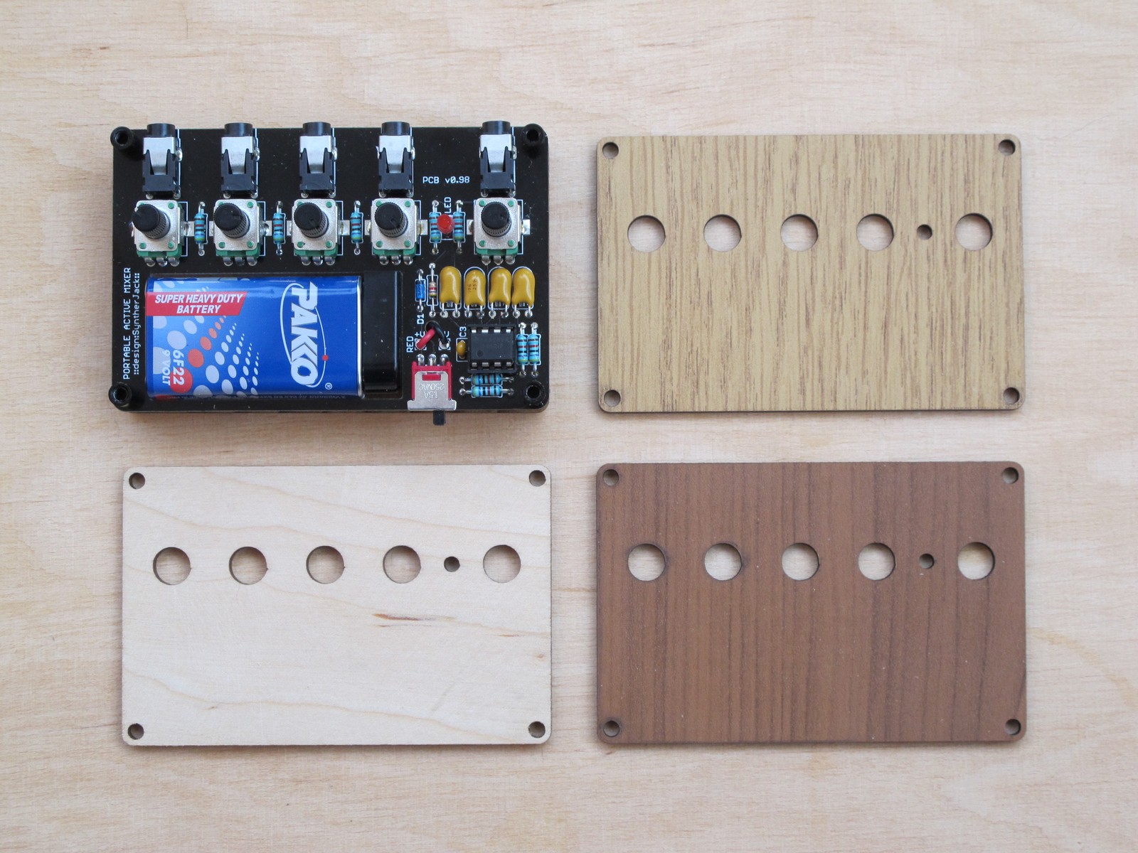
The enclosure
“Enlosure” – said too much. Just front and back 3 mm plate fixed with spacers and screws. My first (and greatest) idea was to use laser cut fake wood. I looked just astonishing, but my girlfriend said it is most ugly thing I’ve ever done – I’ve dumped the idea and moved to plexiglas :/
First prototype (photo above) used black finish 8 mm threaded spacers with round sleeve shape (from GearBest) – those needed two lengths of screws, as they came only in internal threaded version and I had to connect them somehow. The solution was too complex, round spacers were hard to source, so I moved to standard hexagonal. I used 6 mm M3 screws with imbus cut and cheese head, so you can screw them just with your fingers. You don’t need any additional tools.
I had one more slight problem – high quality, machined IC sockets I wanted to used were to high to fit with 8 mm spacers. The next standard length was 10 mm, but then the whole mixer would become more bulky. Finally I decided to move to the cheaper socket type, that was lower and fit better under the panels.
Electrical tests
I performed bunch of tests (mostly for TL072):
- minimum power supply voltage level: 6 V (slightly below IC specs)
Note: TL072 data sheet under “Recommended Operating Conditions” states sum of both supply voltages must be over 10V, but on TI site “Total Supply Voltage (Min)” of 7 V is mentioned; I’ve tested it and distortions begins to be hearable (and visible) around 6 V power supply (equivalent of almost dead battery), although this can be considered as working out of IC specs,
- abuse tests (most fun, because you can burn something!):
- reverse power supply polarity for 1 hour @ -12 V supply: survived (as expected),
- input 12 Vp-p @ 9 V supply for 1 hour (TL072 specs say ~8,3 V): surprisingly survived (not as expected),
- runtime (multiple runs) @ 5,5 mA supply current:
- cheap (<1 euro) 9F22 battery: 96-102 h,
- rechargable “400 mAh”:47-54 h,
- headroom/clipping level vs power supply voltage :
| Supply voltage [V] | Max. output voltage swing [Vp-p] |
|---|---|
| 9,0 | 5,6 |
| 8,0 | 4,8 |
| 7,0 | 3,7 |
| 6,0 | 2,9 |
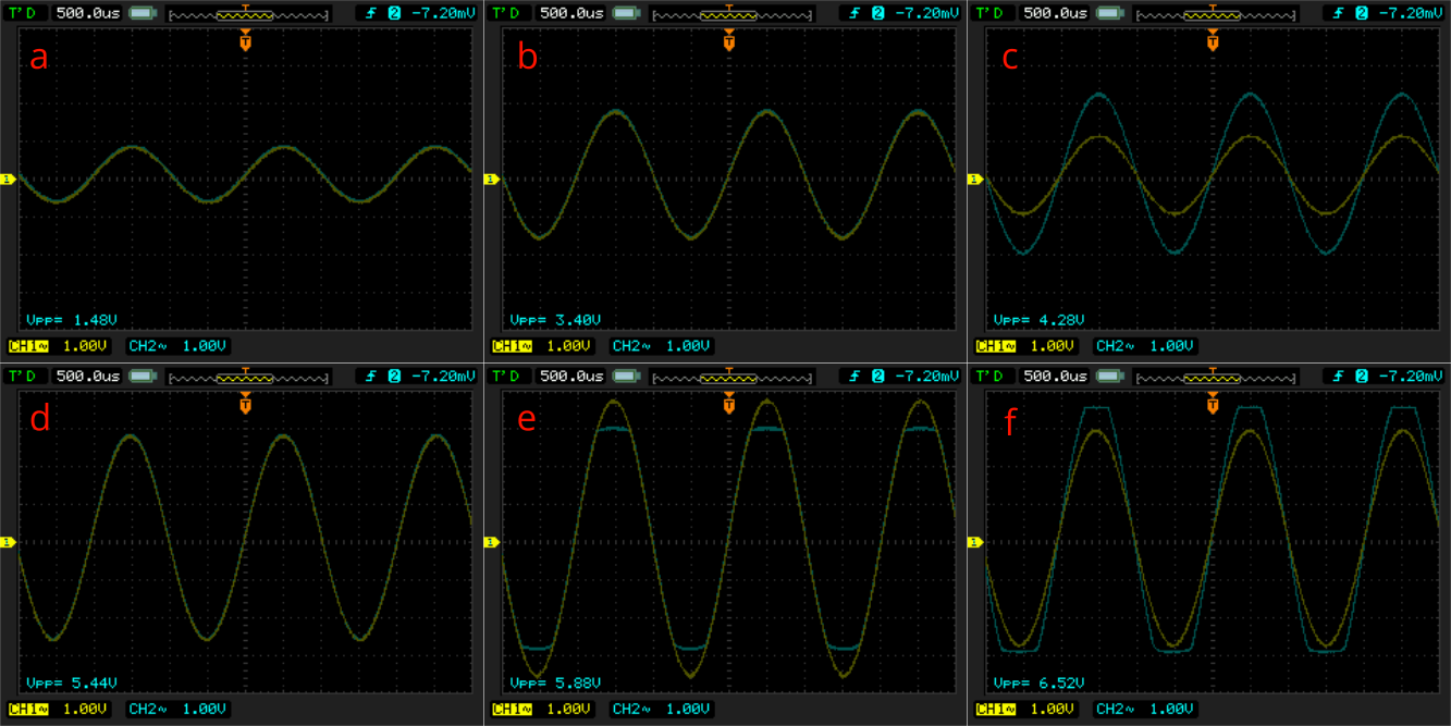
Because I love to play with oscilloscope, here’s something interesting: clipping waveforms. Each operational amplifier has its own parameter called “output voltage swing”. In the best case, with so called “rail-to-rail” amplifier, output voltage can swing exactly between power supply voltages. For example, popular “rail-to-rail” MCP6002 opamp, supplied from +5 V voltage source will give you maximum output of +5 V.
TL072 is not a “rail-to-rail” one and for +9 V supply voltage can output maximum signal of +6 V amplitude. Moreover, for TL072 in 4sum circuit and 9 V battery supply (decreased by protection diode voltage drop – check the schematic), the maximum input voltage is around 8,3 V. So, the whole circuit headroom will be defined by ICs output voltage swing, which is exactly 5,6 V.
I also run fast tests for NE5532, as a lot of people consider it as great choice for audio circuits:
- runtime (single run) @ 15 mA supply current:
- cheap (1 euro) 6F22 battery: 34 h,
- rechargable “400 mAh”: 15h,
- headroom/clipping level vs power supply voltage: almost the same as for TL072 (see table).
So, you can use NE5532 instead, but the battery life will drop (which should be not a problem if you use USB rechargable 9V batteries like the one below).
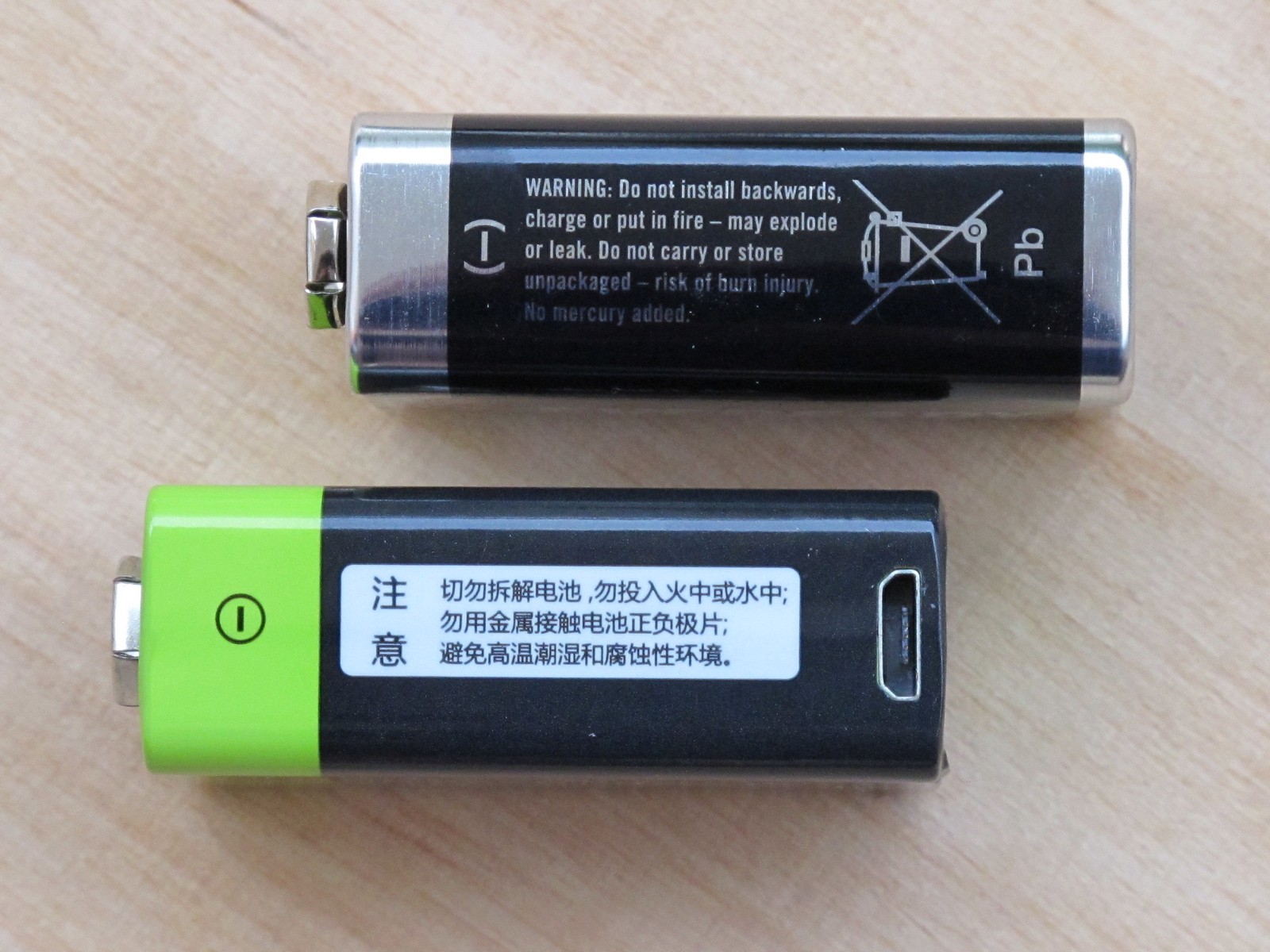
The price for piece is ~8$ with shipping. Moreover, producer claims output voltage is 9 V, which is not obvious for rechargeable 6F22s (often it is a multiplication of 1,2 V).
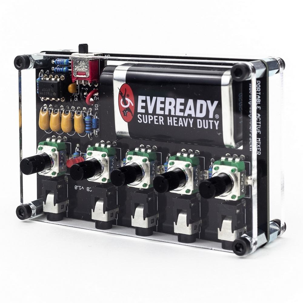
The final build
I’ve already said enough, let the photos do the rest. They were made by my friend Marek, photographing flat plexiglas surface is way out of my league. I was in a hurry and left a lot of dust, I know it 🙂
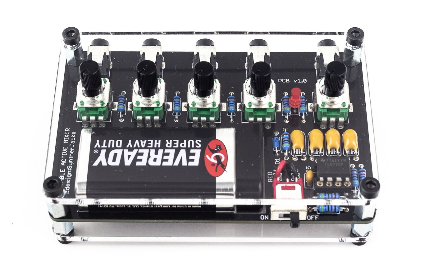
Because of used plexiglas panels, LED is soldered entirely under them (without hole like in wooden cut ones). If you don’t like tiny 6 mm diameter knobs, you can always put your own – there is enough space. In my opinion, as audio level controls they are allright (in opposition to f.e. filters cutoff or resonance – it’s too hard to find a sweet spot).
The following video can you give an idea how you can use 4mix in your setup (generally speaking, as a mixer 😮 ). Here is an example of simple unsynchronised modded Monotron jam – 4sum is a great companion for them! (Audio level is a bit low, I forgot to normalize it.)
Specification
Main features:
- 4x mono inputs,
- 1x stereo (double mono) output,
- long battery life (average 100 hours),
- output in phase with input,
- high quality components,
- designed for portability,
- LED on/off indicator.
Mechanical data:
- size:
- without knobs : 93 x 60 x 29 mm,
- with knobs : 93 x 60 x 35 mm,
- weight:
- without battery: 90 g,
- with battery: ~120 g.
Electrical data:
- max. input signal level: 6 Vp-p,
- max. amplification x2 (+6 dB),
- power supply: single 6F22 battery,
- current draw: ~5,5 mA @ 9V,
- battery life:
- ~100 h (average cheap battery),
- up to 200 h (lithium battery),
- works with rechargable USB batteries.
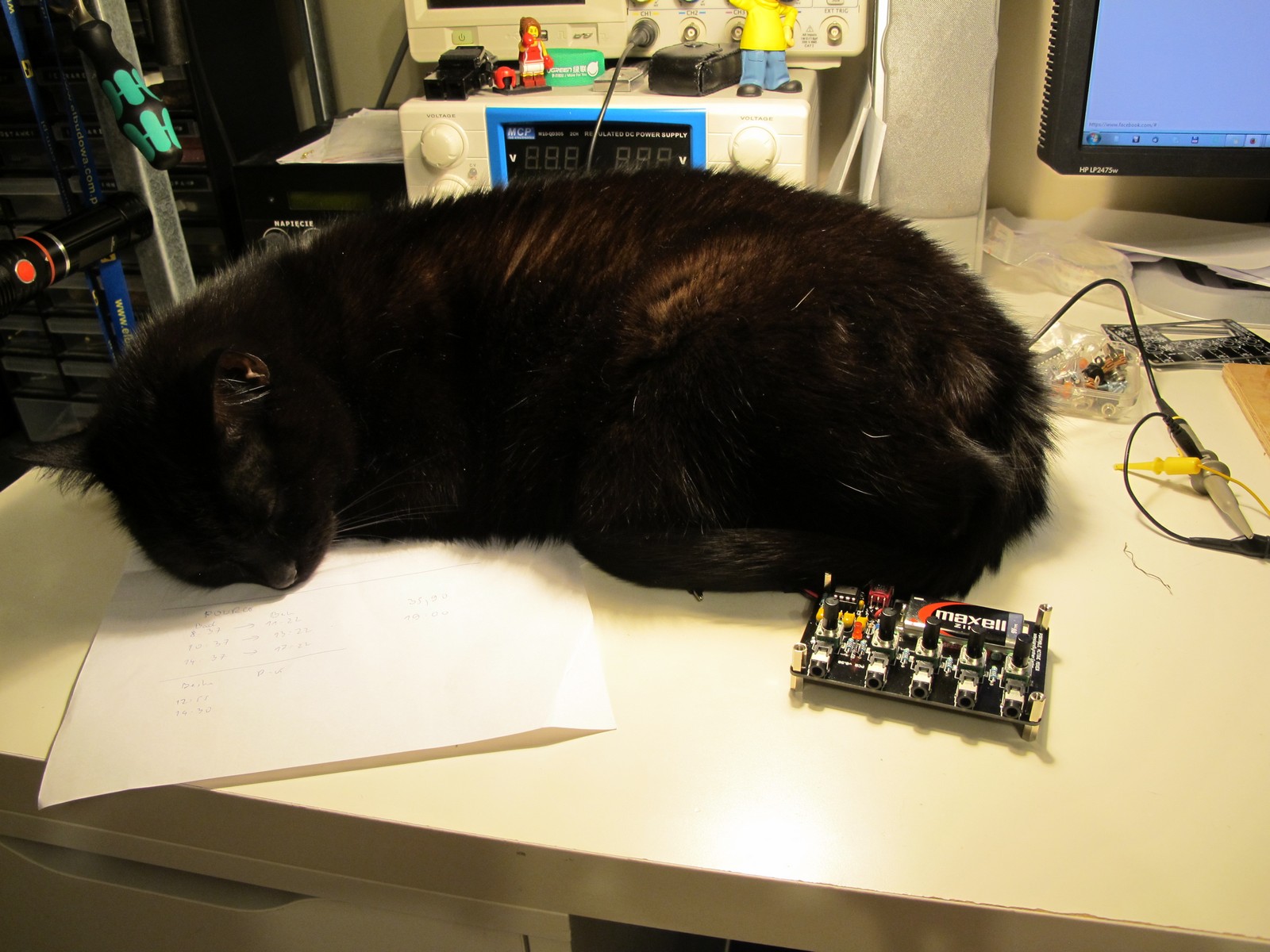
…and if you are courious, why the development took so long, here it is! Totoro loves to sleep near the PSU when I run it, because bench becomes nice and warm (here I turned it off, because of loud fan noise). And you can’t work if you have to cuddle. Cat has always the priority 🙂
And thats the end of my mixer story. If you like it, you can get 4sum portable audio mixer from patch.audio online synthesizer shop as a full kit. You will also find there BOM along with building plans.
Have fun,
Jack
Would it be possible to build a longer version with 6 or 8 inputs that split the first input into left and right (audio and sync) signals and then duplicated the sync signal into 6 or 8 separate outputs? I’m looking for a mixer that can be connected to two of these cases ( https://dichstudios.com/collections/po-gear/products/3po-case ) so that they can be folded with their button sides facing each other. The mixer would essentially be part of the hinge holding the bottom 3 Pocket Operator case to the top 3 Pocket Operator case. The plan would be to have it so that all of the Pocket Operators could be easily transported with all the cables already plugged in and the sync settings set up and ready to go. Could you build something like that and still get it to run from commonly available batteries?
Thank you for your time and consideration!
Mike
Can be done! I will let you know!
I notice the schematic indicates electrolytic capacitors, but the ones you used look like ceramic ones. Can I use ceramic caps instead?
The one I used are tantalum type. Ceramic should also work.
Just built one of these, fun little project .. just a few hints for anyone else that will get the kit: 1. you’ll need a hot soldering iron and fine solder – the resistor holes are a tad smaller than they could be, so be prepared for a bit of fine-work, 2. when you insert the potentiometers, be sure to solder one pad first, then double-check that the pot is flush with the PCB before you solder the next pad .. its boring, but it has to be said: you’ve gotta do one pad first, double-check, then the other. Trying to re-level after you’ve done both pads is a real bore! ;). 3. don’t forget the strain-relief on the battery cable, d’oh! :). 4. its a fun little mixer and really adds a level of control to a monotron setup that is badly needed. Nice one SyntherJack, happy builder here!
Thanks for input! I will include your notes in the next generation of PCBs and manuals!
This looks really quite nice. Could I try to do a stereo version by using stereo pots and doubling up on everything else, or is that too naive? (Very new to electronics!)
Hello! The idea is great, but try to find good quality, small stereo pots 🙂
Hi! Great job with the mixer, it looks awesome! Like other user said, I will give it a try and go for the stereo version (with the NE5532 and a 9v power suply, as I want to leave it on the whole day). Thanks for the project info!
Looks great!
Hello …
Anyone still here ..
Synterjack …
If ic omp TL072 replaced with AD823 is it possible, or is there a component that needs to be replaced
Thank u before
Hello, it should work without any additional changes. But of course can’t be 100% sure until I test it. Cheers!
Very nice project! Thanks for building and for sharing! Great info for electronics beginners like me.
Looking for a small stereo mixer like this, where the input levels can be controlled via Midi CC:
Any hint would be appreciated. Syntherjack, you would not care for crowddesigning one of those, would you?
Hello! I am thinking about small stereo mixer, but Midi CC control would be something new. Unfortunately I don’t have a lot of time right now to start new complex projects. Cheers!
What the capacitor type please? They look like tants…? Thanks
Do you have the plans or files (gerber file) for the PCB board? I don’t need the full DIY kit as I already have all the components. I would appreciate it very much.
Hello!
This is a great project, thanks for sharing! I’m looking for a 9V mixer like this. I read the note regarding the output. However, I only need mono output; can I use a mono jack — connecting the the tip to output and sleeve to ground? Or would that cause any issues?
After some thinking and implementation: this works, of course. Thanks again for sharing the schematics!
Where does the 9+ go, right before the voltage divider (VREF)? I figured that would have to get tied to the op amp somewhere
Where does the 9+ go, right before the voltage divider (VREF)? I figured that would have to get tied to the op amp somewhere, I am not seeing it in the schematic.
@David The TL072 will need to be fed both 9+ (pin 8) and ground (pin 4). It’s conventional not to show power supplies to op amps to avoid clutter on the schematic.
A 6-8 channel version of this with a send/return or 2 would be so awesome! Would this be difficult to implement? For example, can the 6-8 channel version be made just by copying the seperate channels multiple times?
Hello! I’m looking for a compact box that basically does the inverse of this; takes one input and splits it to 4 simultaneous outputs. Would it be possible to modify this design so that it behaves in this way?
Thanks!
Is there a git repo with the gerber files? Thank you!