Long story short
Ocean Noise Generator (as the name says) generates stereophonic ocean-like noise, by simulation of background noise and different kinds of waves (“close” and “far”). The device is built around 2 white noise generators, 4 filters (to get pink and kind of hi-frequency boosted pink noise), 4 VCAs controlled by 4 LFOs with variable waveshape and modulation depth. By mixing generated signals you can go from waterfall-like sound to gentle sea or storm if you like. All this is 100% analog.
Originally, the main usage was supposed to be ambient mixes for chill out-zones, but it greatly will serve as well as a home relaxation device, may be also useful for yoga classes. As the white/pink noise generators quality is not bad, will work as a backup, two-channel, generator for simple measurements.
The general idea
The generator was my side project for around 4 years, most of the time I spent figuring out how to get the ocean noise synthesized. The core was obvious – the pink noise, which alone sounds like a waterfall or very rough ocean. To make the simulation more natural, wave sounds are added – “far” waves, bass, and spatial, breaking lazily in the distance. The other are “close” waves, smaller, washed ashore, with the well-defined direction they come from, and more high-frequency components. As a final touch, a bit of white can be added to reproduce the noise of the wind.
Prototyping
Before I moved to circuit prototyping, I decided to test the concept using VCV Rack – a software modular synthesizer. I couldn’t model all nuances (like _/\_/\ half-triangle waveform), but it was still great to verify the idea.
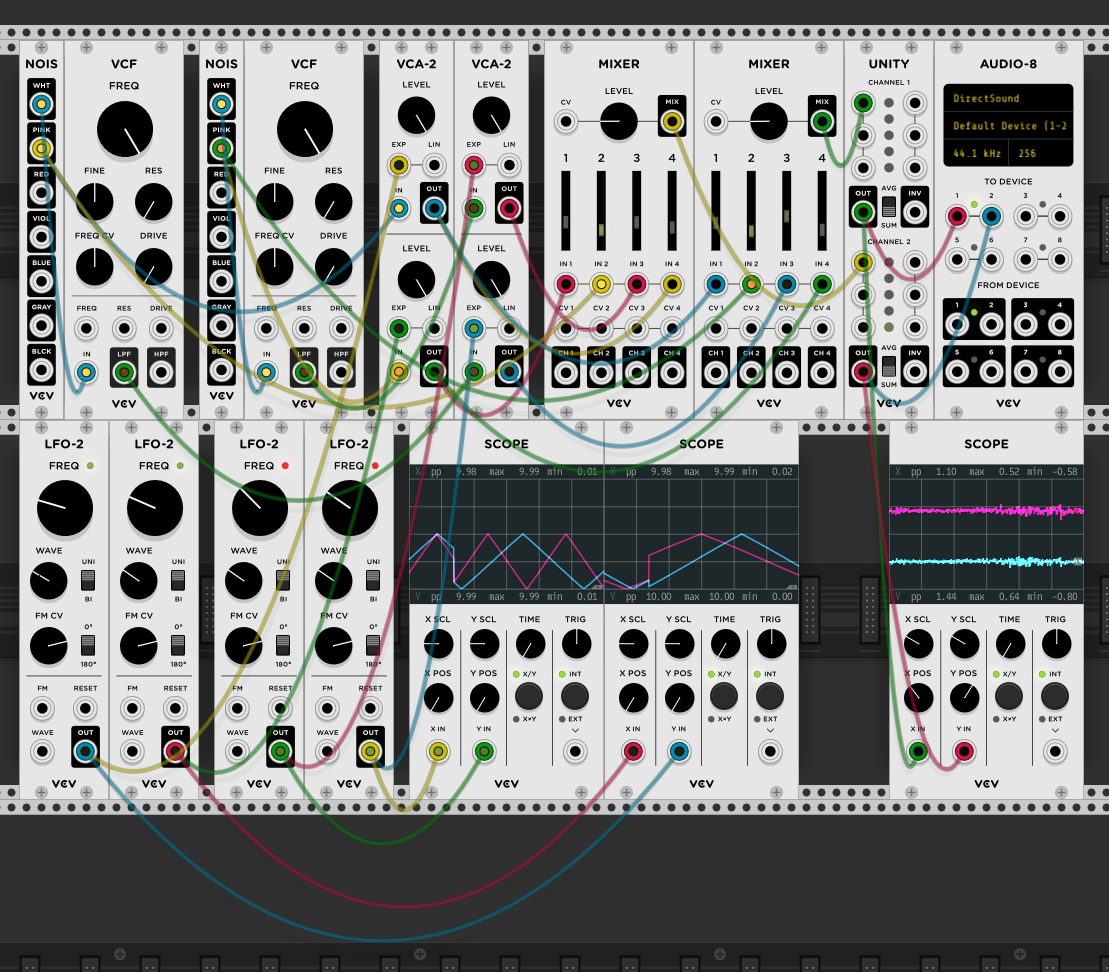
In the rack above:
-
“core” noise (simulated by pink noise NOIS module, separate for L and P channels),
-
“far” waves (pink noise from NOIS with amplitude modulated by triangle LFO (VCA-2 + LFO-2), separate for L and P channels),
-
“close” waves (white noise low-passed around 4 kHz (VCF module) with amplitude modulated by triangle LFO, with L and P channels mixed to get panorama narrower than “far” waves),
-
“air” noise to brighten overall sound (simple white noise separate for L and P channels).
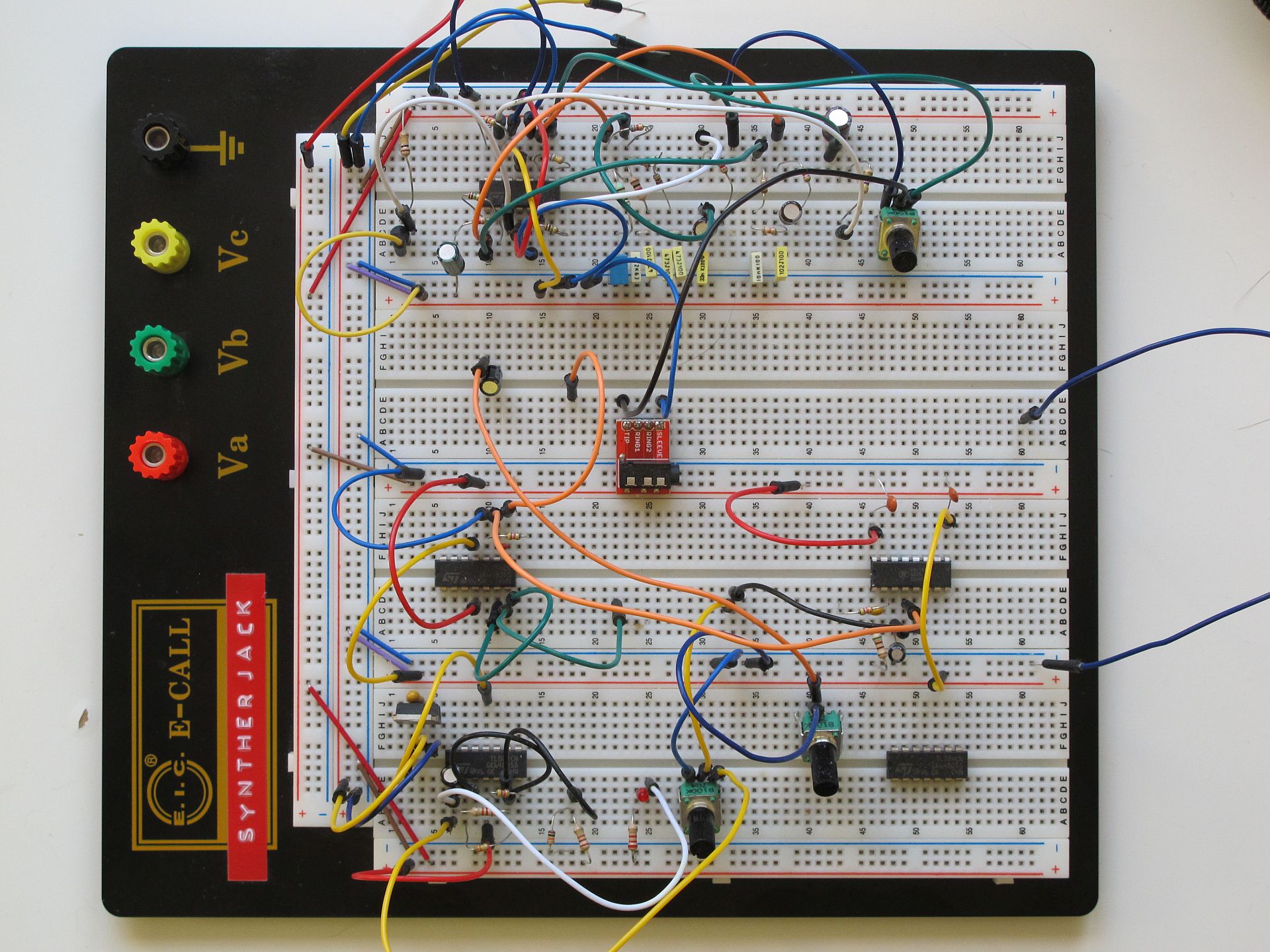
I’ve also built a simple hardware prototype, just one pink noise generator with output amplitude modulated by triangle LFO. I wanted to test the AS2164 VCA and LFO circuits to see how much I can simplify them.
The circuit
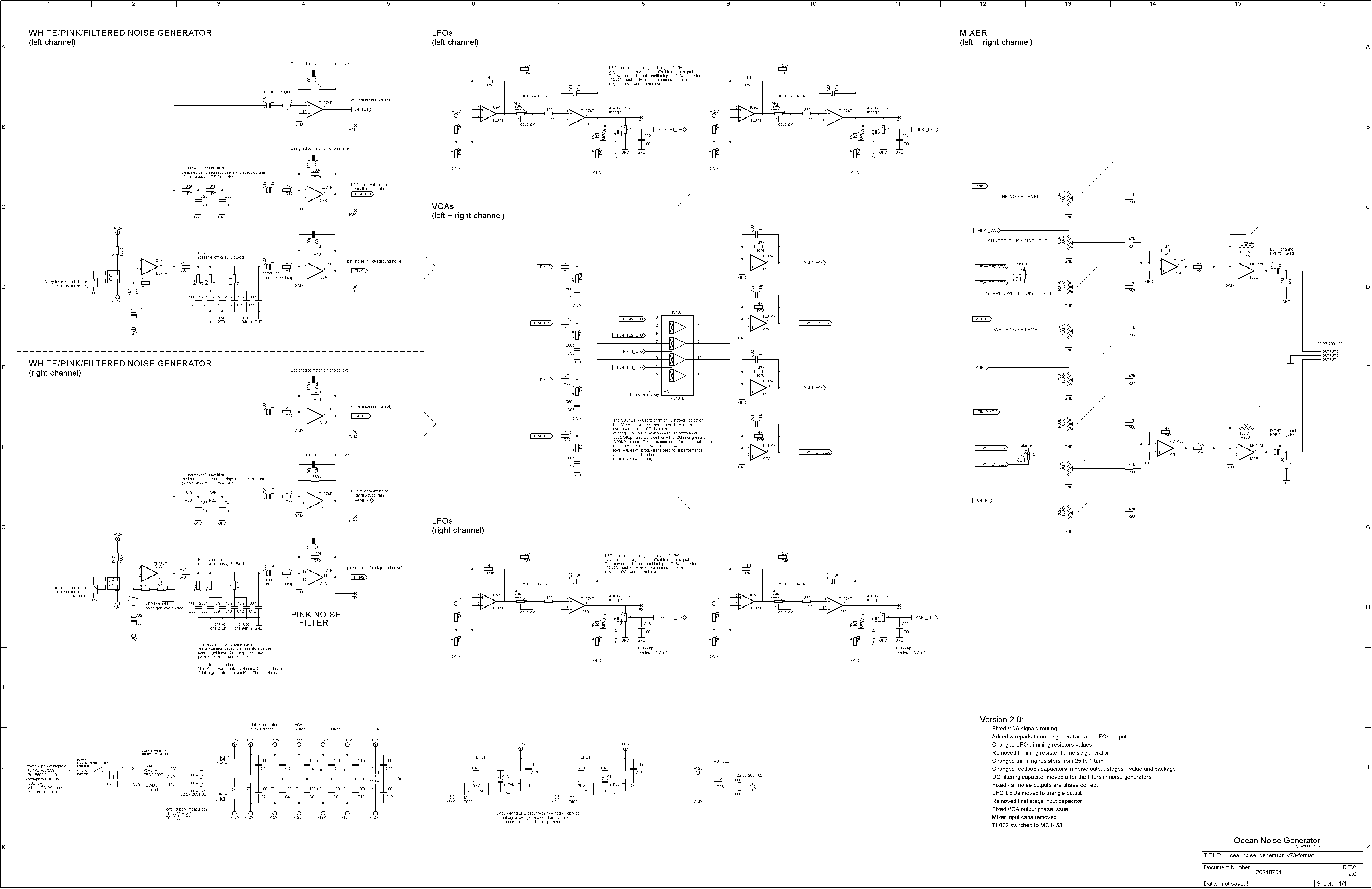
The almost full schematic is here – the main voice board, excluding the power supply circuit, which is application-dependent (you can still jump to the PSU section and read about it). 99% of components are easily available, only AS2164 quad VCA IC may a harder to obtain.
Block diagram
The core of the circuit consists of 2 identical circuits, for left and right channel, sharing output stage mixing controls. Both channel’s signal path is connected only in one point – where the “close wave” sound stage is being narrowed. Block diagram will explain the basics of the devices topology:
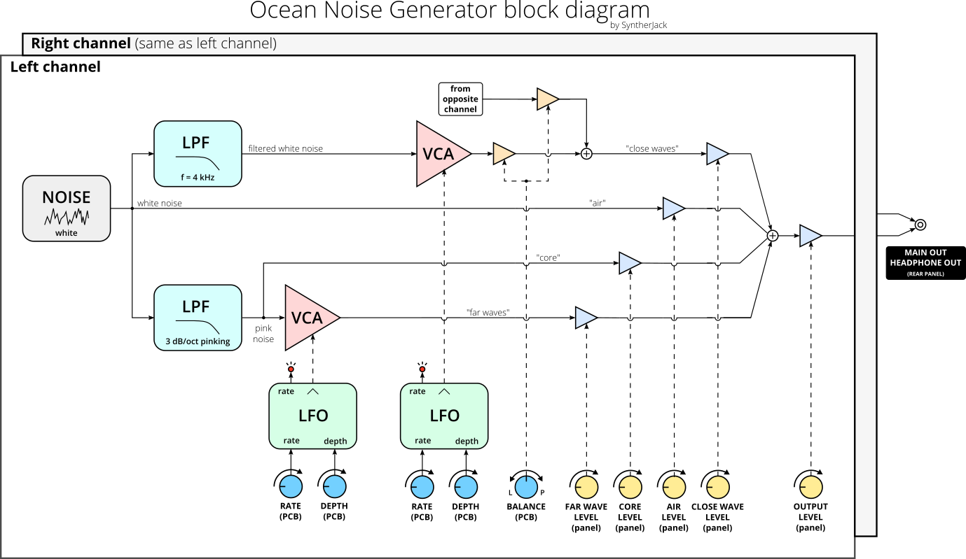
The white noise generator is based on a BC547 transistor (socketed, so you can easily change them). Then the output of the generator is split into three branches:
- first goes through a simple 2-pole RC low pass filter with a cutoff frequency around 4 kHz, then amplitude modulated by triangle LFO, finally mixed with output the opposite channel to make stage less spatial – small waves washed ashore are quieter and easier to locate than rumblers in the background, thus sound stage narrowing
- second flies straight to output and simulates gentle wind and general high-sounding noisy foaming
- the third is pink-colored in another LPF, then one part is amplitude modulated with triangle LFO creating “far waves”, second goes untouched as “core” or “background” noise.
VCA was created using single AS2164 in its standard application, noise generator and pinking filter are also well-known designs. But LFO is a different animal.
The LFO
The problem is, AS2164 VCA in its simplest application is fully opened with control voltage at 0V and closes as voltage goes up. This is not a big deal when modulating with triangle, but makes LFO more complex as an additional conditioning circuit is needed – to add/remove offset and change amplitude. In the most common triangle (square) LFO circuit, Vref = GND, and the power supply is symmetrical (f.e. +/-12V). The generated triangle is around +/- 10.5 V.
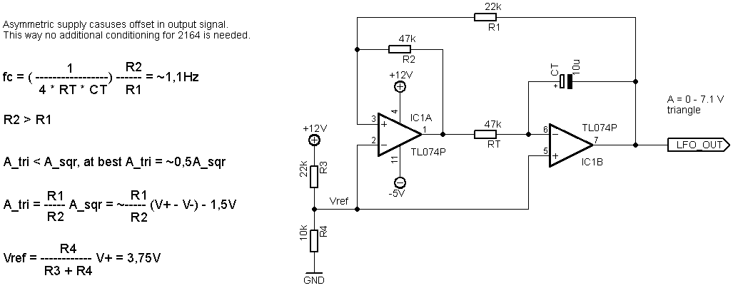
In the above circuit Vref > 0V, therefore the constant component will appear in the output signal. In my circuit, the target was to get LFO output from 0V to around 7V, so also a drop in amplitude from around 10 to 7V was needed, so negative rail voltage was reduced to -5V. Why 7V? As the CV goes above 5V, the VCA output goes practically silent. So between 5-7-5V cycle (top of the triangle), we have no output, which makes modulated noise more wave-like (wave – silence – wave – silence, mentioned above /\_/\_ reversed vampiretooth waveform).
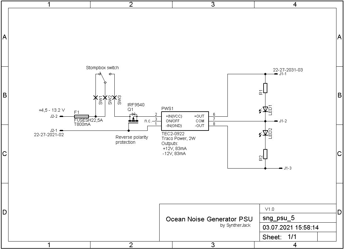
Power supply
PSU was a separate project – I didn’t want to include it on the main voice board, as it is application dependant – different for a stompbox, eurorack, etc. The heart of the circuit is the Traco Power TEC2-0922 DC/DC converter, with +/-12V output and a wide supply range – from 4.5V to 13.2V (so you can power synth from USB, 6xAA, 3S LiPo…). Fuse serves as overcurrent and IRF9540 as reverse polarity protection. Two LEDs will ensure the converter still works.
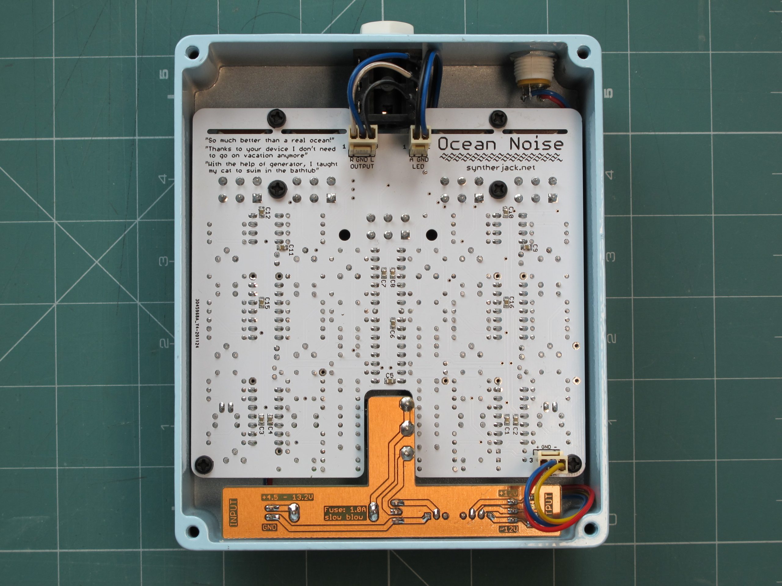
PCB
This is a second review of the PCB, manufactured by JLCPCB. The first one used 25-turn trimmers, very uncomfortable to use. Who needs 25 turns to set balance or LFO level? It was surely an overkill, so I moved to single-turn ones. Trimmers can be also soldered on the bottom side, making tuning easier with PCB installed inside the housing.
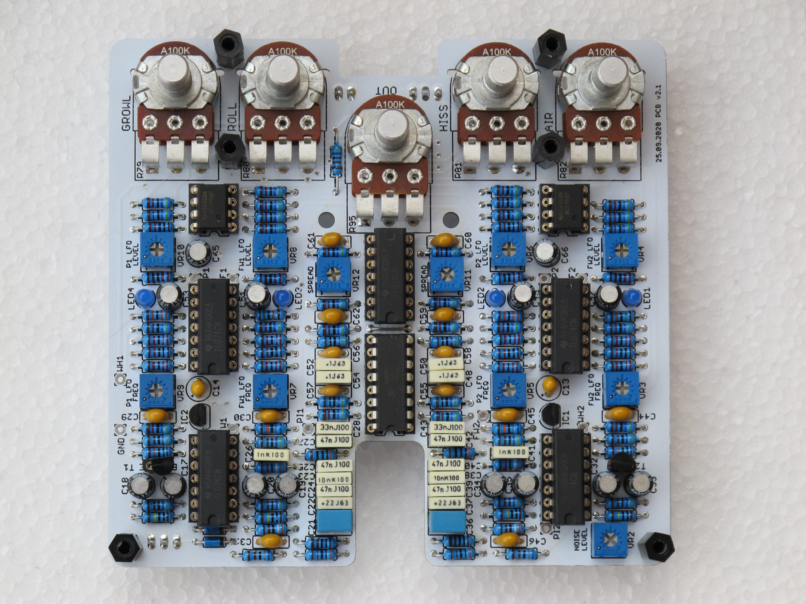
The spacers are not for PCB fixing, but rather to keep a safe distance from the enclosure when tightening potentiometer nuts. Narrow slots under the potentiometers allow breaking the PCB to exactly 100 mm high, just in case someone would like to make an eurorack module out of it. I’ve added also outputs of all noise generators and LFOs for modders (marked on the schematic). Four blue LEDs, buried inside the case, give information on set LFO frequencies (connected directly to triangle outputs). Blink-hungry synthesists can expose them, but I wanted to keep the case clean.
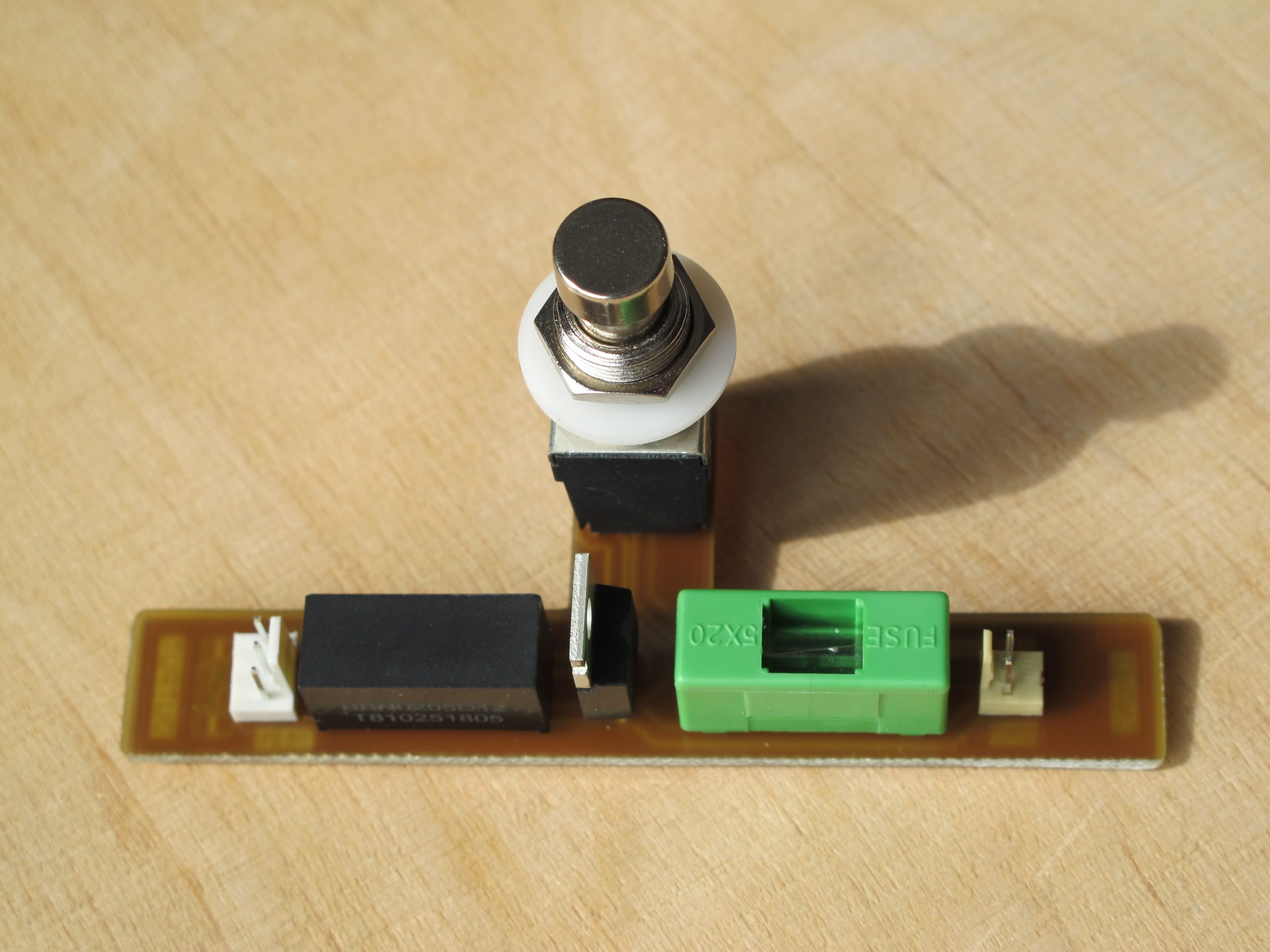
Power Supply PCB is shaped to fit on the stompbox switch and perfectly fills the space remaining in the housing. Two LEDs are SMT mounted on the bottom side. Fuse holder placement is a bit uncomfortable and you need to remove the switch (along with PCB) to change the fuse.
Enclosure
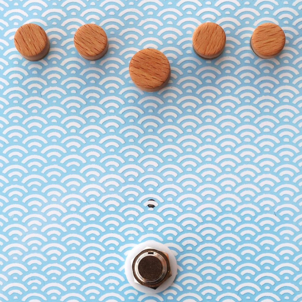
I went full-stompbox, not sure why :/ I treated this project as a playground to check some of my ideas. The first one – white pattern painting with 3D printed stencil. Second – DIY wooden knobs made with a bench drill press and plug drill. I’ve chosen 1590XX style aluminum diecast in light blue from Tayda.
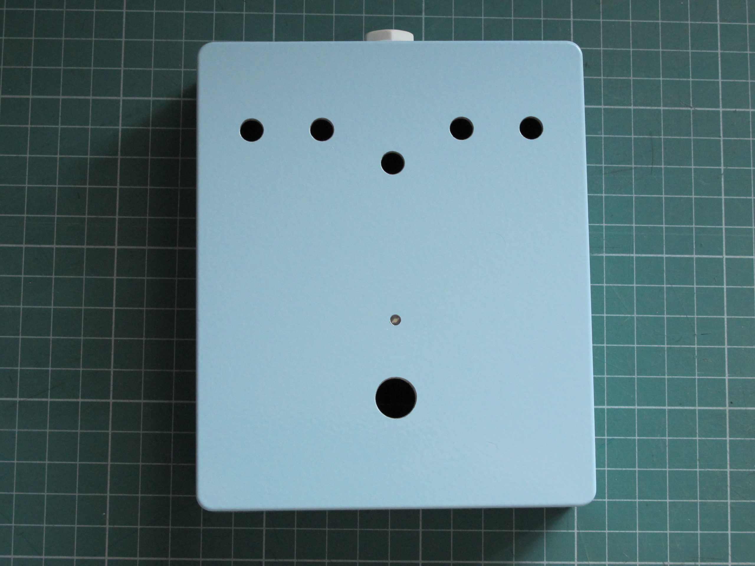
Drilling!
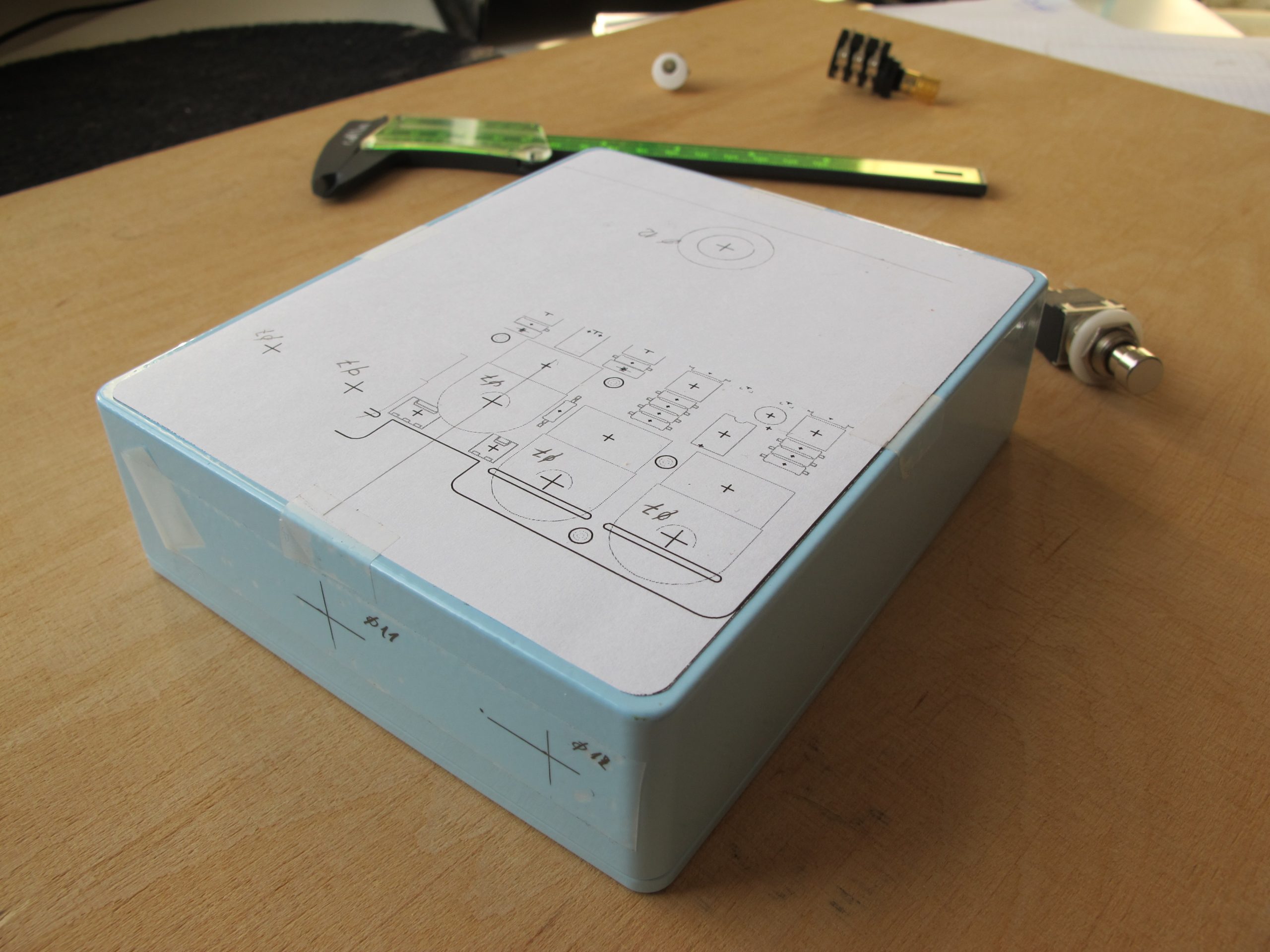
But first, traditional photos of measuring and drilling. I use PCB/parts outlines printed on paper to mark the exact position of the potentiometer and socket drills. Scotch Magic tape is amazing for early paper-based prototyping, as it leaves no glue and you can write on it.
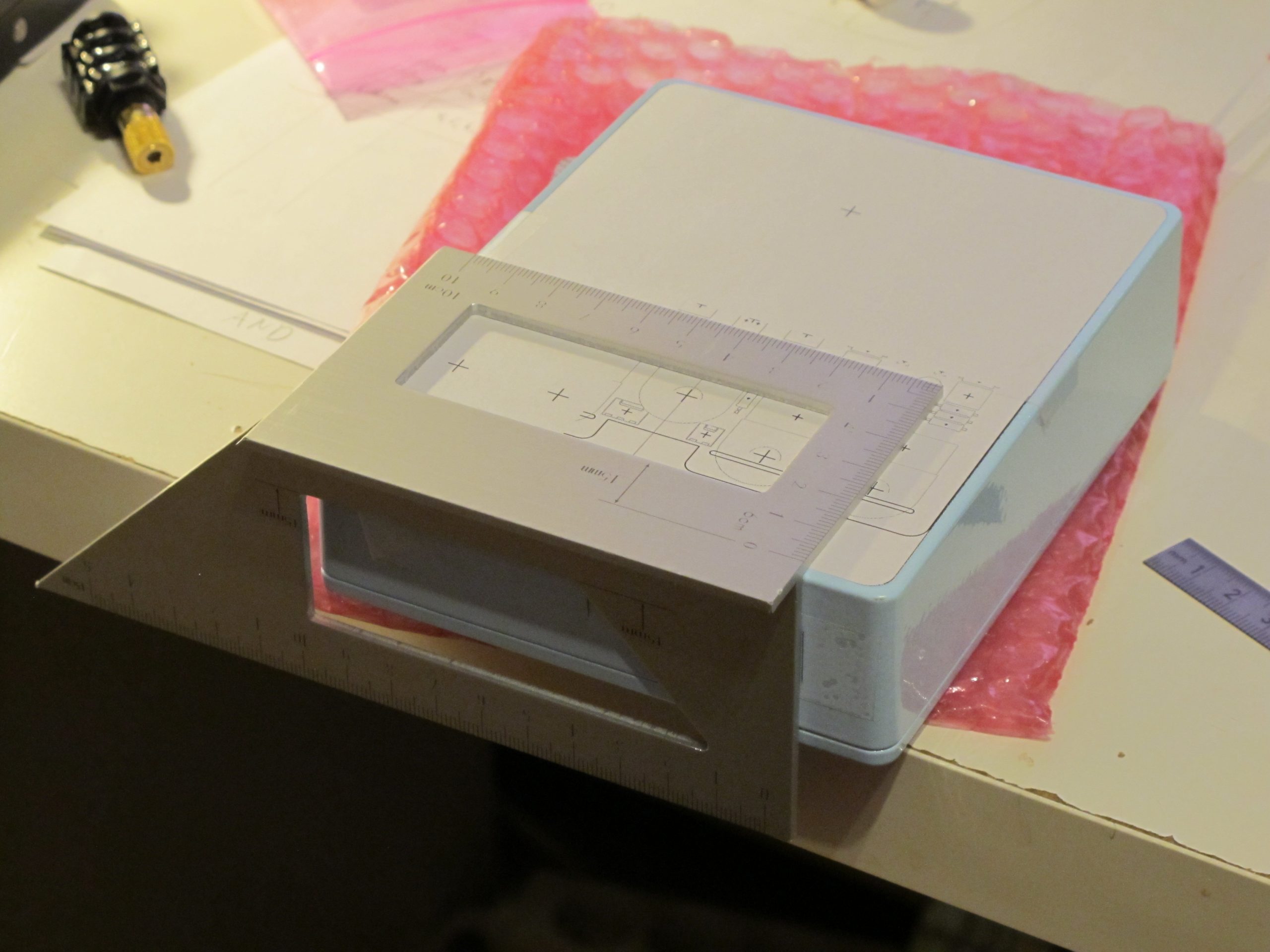
Now is the time for a beer or coffee (or both) and considering if everything is done correctly. (In fact, it was not! In the photo below, you can notice that the bottom right 12mm hole may be too close to the housing’s internal fastening thread. But I will notice it after drilling.)
Now, when I think about it, it may be a better idea to drink just water :/
A clean workspace is the basis of success. And with proper cat supervision, you just can’t go wrong. (In fact, you can, cats totally don’t care if you fail.) Btw Bosch PBD40 works great in tight spaces, also fits in a closet if I’m not using it. My wife is very understanding.
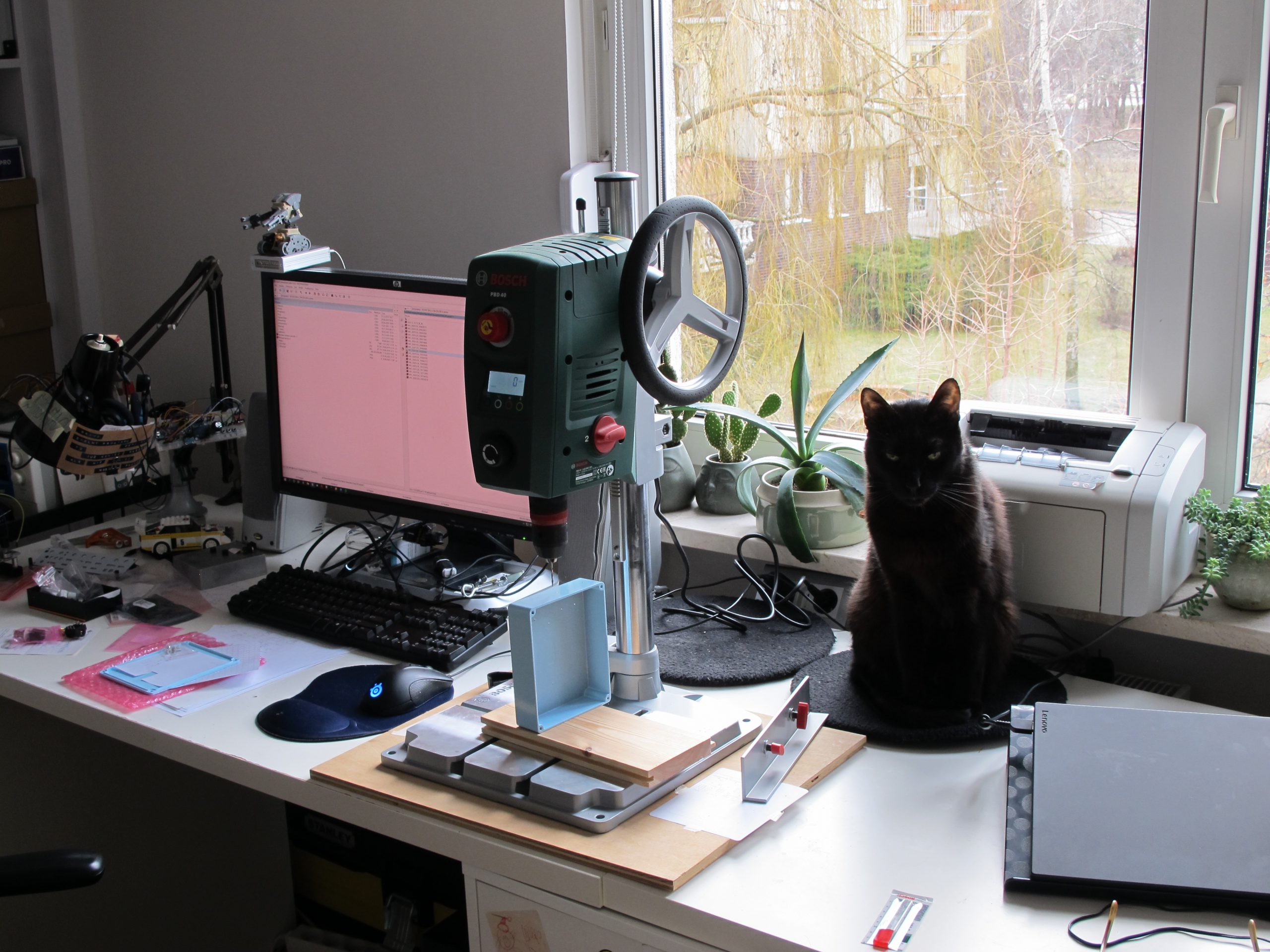
As always, I started with a hole punch, then a 2mm drill. Drill press saves o lot of time – now I can use step drills instead of traditional ones, so 12mm holes are no big deal.
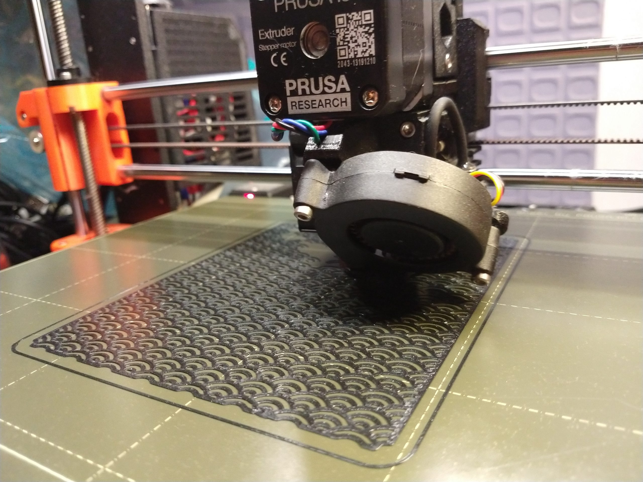
3D stencil and painting
My idea was to print through the stencil and paint the pattern directly on the housing. This approach had 2 problems:
- printing had to be done perfectly the first try,
- it is very easy to cratch.
The compromise was to apply paint on the thin foil, then glue it to the case – print is well protected and you have an infinite number of attempts.
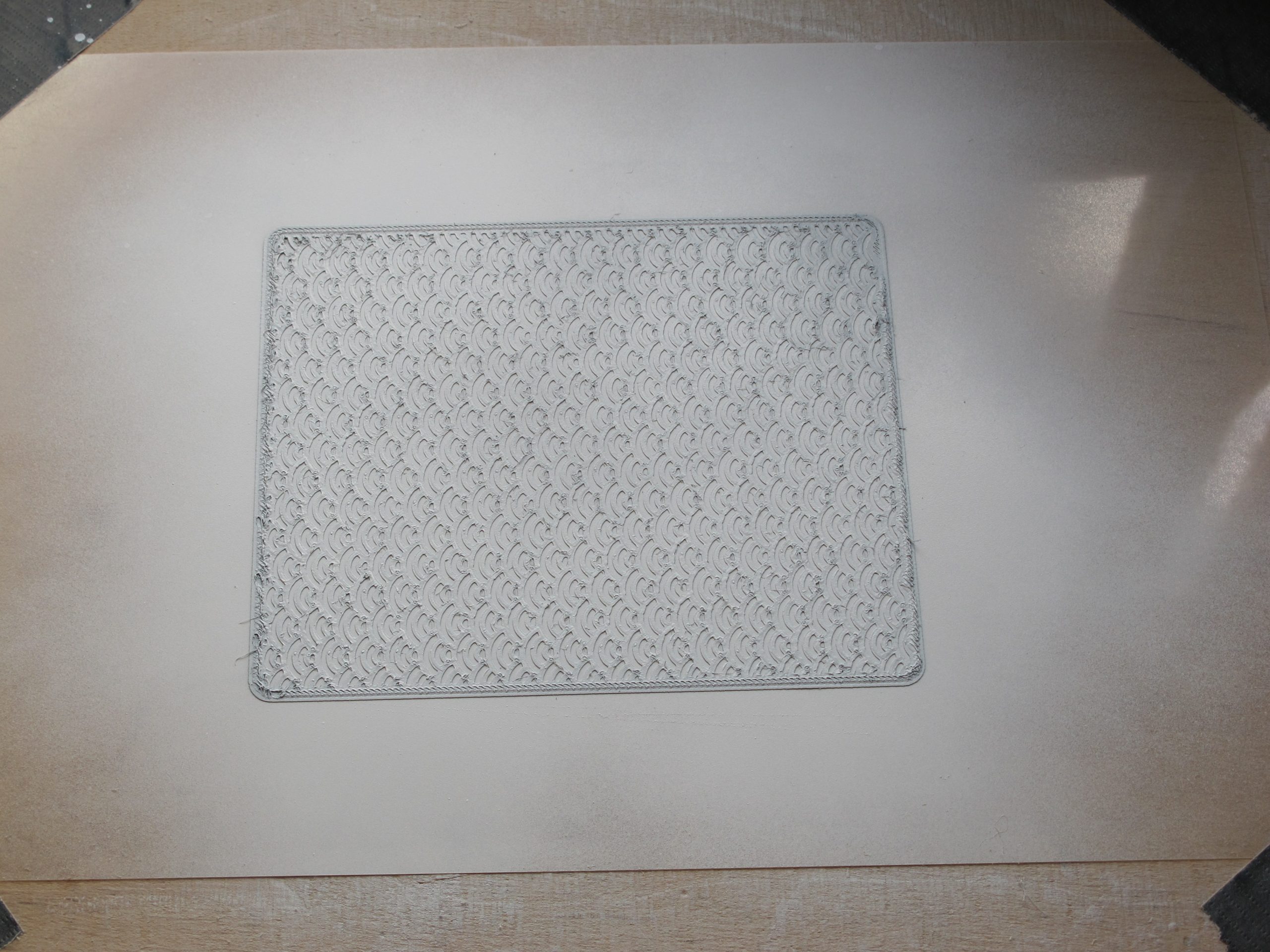
The pattern is based on popular “Japanese waves”, scaled to fit knobs radius and position. The print is not perfect, there are small fibers across unprinted spaces (exactly where paint should go). After few attempts, it became clear it is better not to touch them – removal of fibers with tweezers is too laborious, with sandpaper undulates the print.
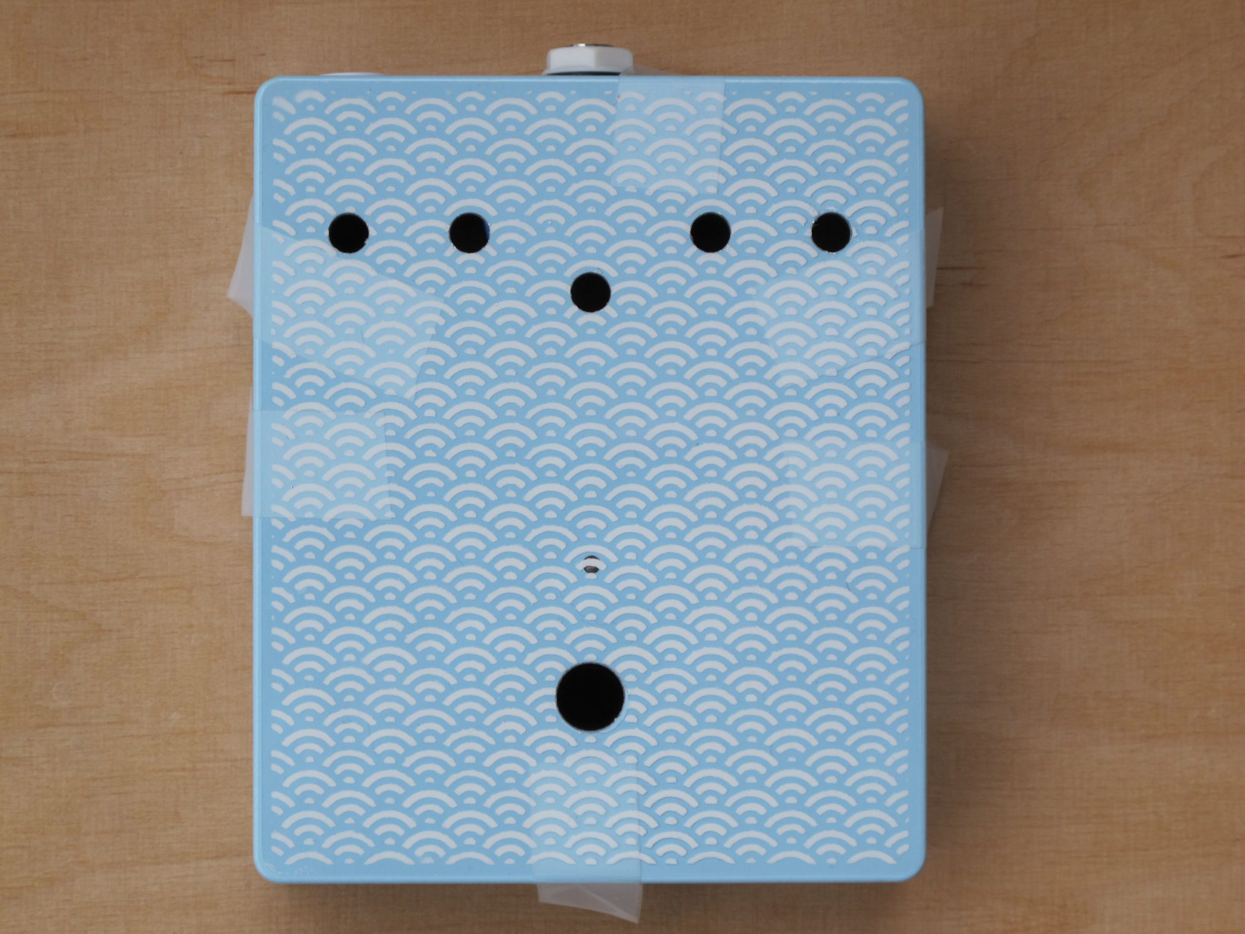
Before printing, the foil was fixed to a piece of plat plywood. The stencil itself was glued with temporary adhesive spray, to prevent paint from soaking under the 3D print, then pushed gently with a painting roll. My wife handled the painting with acrylic spray, as she has more experience and patience. Many thin layers are the key. It really worked out great, but to be honest, the process is tricky. The advantage is, in case of miserable failure, you can reuse the stencil.
The final step was to fix the painted foil with tape (to prevent any movement) and cut the holes for controls. The foil is fixed to the housing only with the potentiometer/switch nuts – it is so flat, it almost sucks to the surface. And it looks simply amazing. Shiny, but modest.
Putting everything together
It fits (almost) like a charm. I was never so happy with my work, although I had to file off a bit of PCB behind the jack socket, the fitting was just too tight. I also spend a lot of time looking for a white 6.3mm stereo jack, but I didn’t found any. I’ve ended with Cliff LC1232A black socket and Cliff CL1409 white nut. Potentiometer knobs are another story and will be covered in a separate post.
Demo
Quick demo, so you can get the overall idea. Recorded using Zoom H4n and Wieheister (universal audio signal router).
Sounds better than the real ocean, isn’t it 🙂
Edit (2021-11-16) Check the implementation of the Ocean Sound Generator algorithm for Monome Norns, by AnoikisNomads!
Cheers
Jack
Such a wonderful project!
Is there any reason why you didn’t go for an all-smd build? I imagine you’d be able to shrink the footprint by a huge amount. If you end up one day publishing the schematic, I may have a pop at it myself!
I’d imagine a lot of the ambient eurorack crowd would be well into this, too.
BTW this website has been a real inspiration for me over the last few years, and I’d just like to say thanks for putting all this stuff up for everyone to see and learn from. Many thanks!
really nice!
is it possible to download the VCV Rack patch?
from the screenshot it gets very confusing, thanks!
Bonjour, superbe il peu servir pour une introduction l’une de mes composition s
Hey,
is the ocean generator for sale at the moment?
Warm regards,
Johannes