
All the designs were used only for comparison and not for any commercial purposes.
At the beginning…
Around a week ago I’ve got a strong internal need to synthesize a sea waves sound (we don’t have an ocean in Poland), as I try to design an updated version of my Binaural Beat Generator. Usually, this kind of synthesis starts with pink noise, later shaped with VCF or VCA modulated with sine (or triangle) LFO. The problem was, I had no pink noise generator. It seemed like a fun project, so I started to dig for some schematic. First of all, I’ve chosen 3 of the most popular that looked as they have a chance to work:
- MFOS “Pink Enough for Me” noise source
- Elliot Sound Products “Pink Noise Generator for Sound Testing” (with basic filter)
- Noise source with passive filter, published among others in ” The Noise Generator Cookbook” by Thomas Henry
The circuits were so simple, I’ve decided to build all of them to check the differences in generated sound. I think my more practical article will be a good read along with the one from experimentalistsanonymous , as it covers simulation and theoretical filter characteristics of pink noise generators).
Idea and prototyping
All popular analog pink noise generators share the same topology: white noise source, then -3 dB/oct lowpass filter. “White noise” part is an easy one, the problem lies in the tricky LP filter design. To get flat -3 dB/oct response filters are quite complex and often use uncommon part values (replaced by parallel common capacitor connection).
I’ve breadboarded (from top):
- pink noise source with passive filter – 24 parts*,
- Elliot Sound Products “Pink Noise Generator for Sound Testing” – 21 parts*,
- MFOS “Pink Enough for Me” generator – 23 parts*.
(*) 1 opamp = 1 part, decoupling caps counted in
All schematics say “+/- 12 V supply”, but I used 6F22 battery pair (+/- 9 V) to power the breadboarded generators [I had problems with oscillations/ground loop (?) in MFOS design as I used lab PSU].
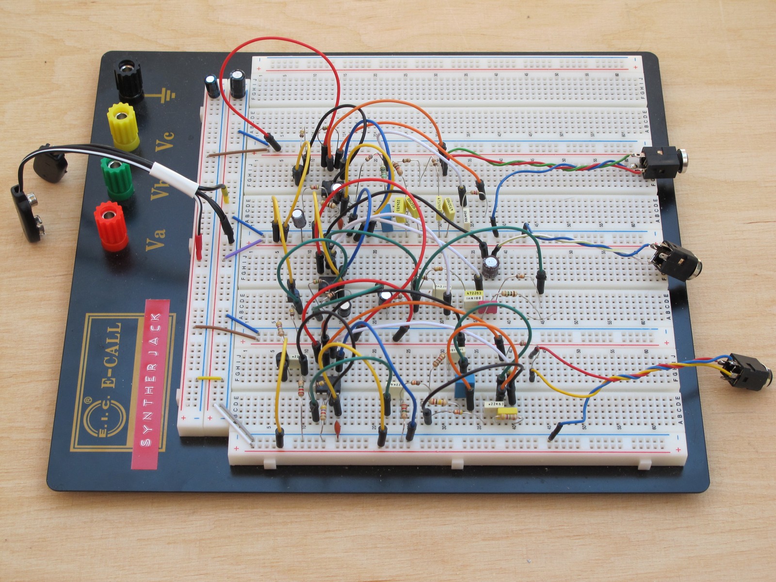
The output from each generator was later fed to a mixer to tune volume levels, then recorded via PC soundcard.
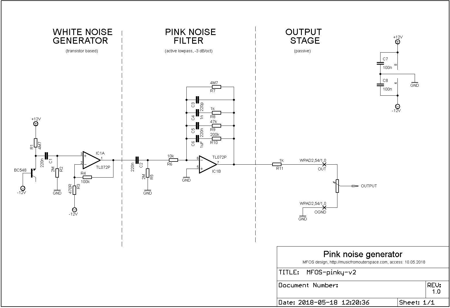
MFOS “Pink Enough For Me” noise generator
It is a very common circuit with a white noise source (transistor based) and an active lowpass filter. All resistors and capacitors are common and easy to get.
After I first prototyped this generator I thought I made an error in component placement or switched its values. There was almost no low end in the noise. I checked everything over 5 times, but after looking for other people’s experiences with this circuit – yes, that’s how it works. I wouldn’t call the generated noise pink :/ Hear by yourself! (wav, mono, 16 bit)
Don’t forget to check the original MFOS design page. Maybe you will have better luck 🙂
Noise source with passive filter
This filter design can be traced down to “The Audio Handbook” by National Semiconductors from ’70, and with some small modifications can be found in “Noise Generator Cookbook” by Thomas Henry. It is told to have very flat +/- 1 dB response. Sounds really pink and natural. You can almost feel waterdrops on your face.
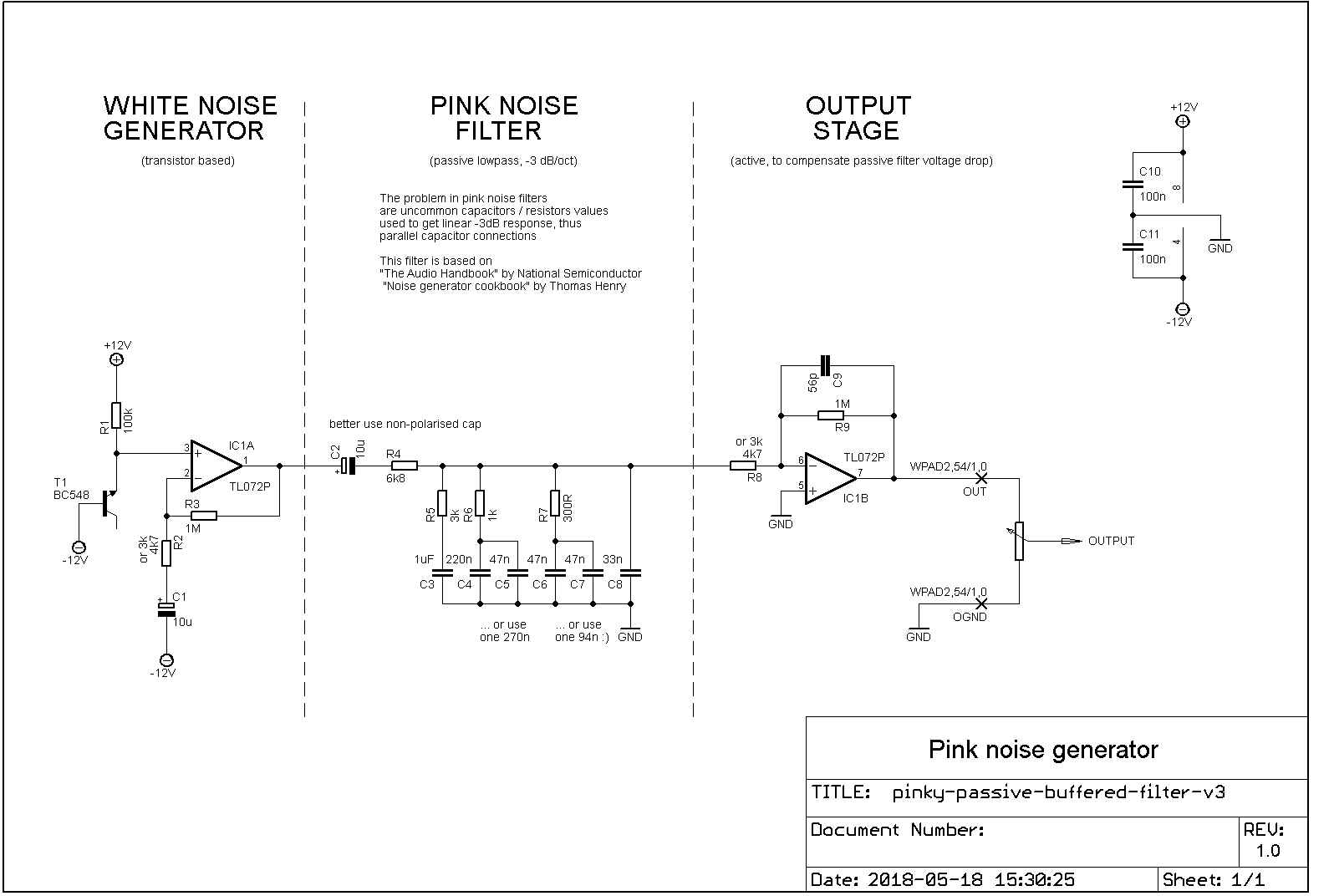
I’ve added a common white noise source (with a lot if amplification) and an active output stage – the signal drop on the passive filter is great and there was the need to compensate it somehow. The hard-to-find 270 nF and 94 nF capacitors were replaced by parallel connection of more common ones.
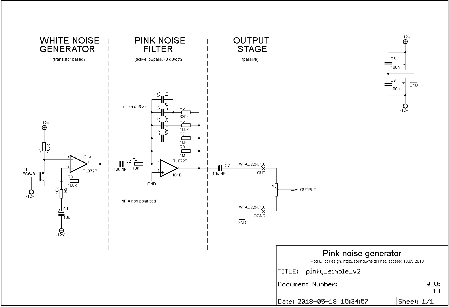
Elliot Sound Products “Pink Noise Generator for Sound Testing” (with basic filter)
This is the simplest pink noise source you can find on Elliot Sound Products page (an amazing source for general audio circuits). The more complex one uses an advanced pink noise filter, and the super expanded one includes an IEC 60268-1 defined band limiting filter. I had problems with getting 5,6 nF capacitor, so I replaced it by 1 nF and 4,7 nF parallel connection (5,7 nF, but assuming 10% capacitors and 5% resistors it shouldn’t make any difference).
This one is a pinkest of all, an instant waterfall. Turn off your mind, relax and float downstream.
The official project page will very detailed description and you can find it here.
Noise generators comparison
You can see four spectrograms – outputs of four pink noise generators. From left:
- MFOS “Pink enough for me”,
- noise source with passive filter,
- Elliot Sound Products “Pink Noise Generator for Sound Testing” (with basic filter),
- reference – pink noise from Adobe Audition.
…or just listen to the recorded sample – 10 seconds of noise, then 1 for relaxation and so long.
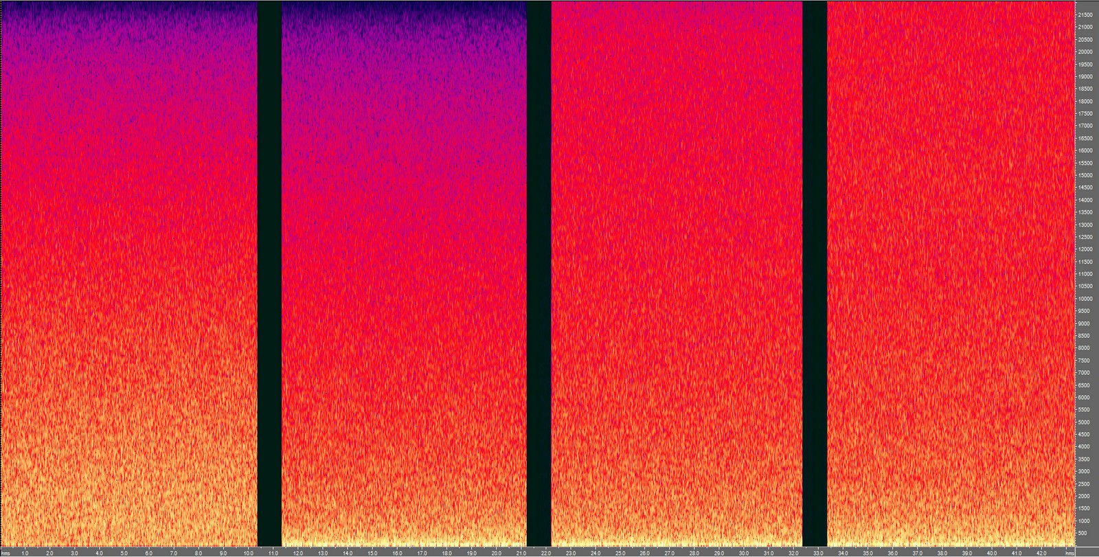
You can notice few things:
- MFOS has problems in the linearity of filters cutoff (not enough lows and augmented mids) and is furthest from the reference noise,
- version with passive filter has low/mid frequencies (up to around 4 kHz) very similar to reference pink noise and is not as bad as it seems,
- ESP noise generator is very close to reference with a slight difference over 10 kHz (reference noise is a bit brighter).
I also made blind tests and some people said passive sounds a bit more natural (like ocean or waterfall), even if it is not perfect. ESP sounded too sharp to them and annoying, even if in theory more correct.
Conclusion
I would recommend listening to a sample and choose between ESP-designed or “passive” version. ESP version would be great for audio testing as it sounds more correct according to theory, but many will like “passive” for use in sound effects or noisemakers, as it sounds less harsh. Remember, the one from Elliot Sound Products can’t be used commercially without written authorization.
And if you want to know more, check the articles like:
- “Pink Noise’ Is The Most Millennial Secret To Getting Those 8 Hours Of Sleep” 🙂
- “Is Pink Noise The Secret To Sounder Newborn Sleep?” 🙂
- “Why Pink Noise Is The New White Noise” (!!!) 🙂 .
Yeah, pink noise is THE THING.
Cheers
Jack
Greetings from Ohio!
My name is Luke Miller. I thoroughly enjoy the content on your site. I’m a novice electronics/synth tinkerer (and lover of ambient noise). The comparison between simple pink noice circuitry is great, especially for someone just learning the basics. Keep up the work.
Thank you & Cheers!
Luke
Hi, if I reverse base emitter junction of transistor 2N3904 NPN transistor(T1) so that it works like a zener diode. I did some of the researches and found that the transistor will be come very noisy. May I know why is this happened? Also, May I know what simulation apps are you using to simulate the results? thank you very much
> … we don’t have ocean in Poland …
ehhhh, ever looked at a map?
Yes and I’m quite shure Baltic Sea is a sea, not ocean. But in case of generated sound, they should be similar.
Stupid questions, from a beginner…. What is the symbol leading to the output (rectangle with arrow pointing out). Is that a trimmer pot? Also, what is WPAD2,54/1.0 x OGND?
Thanks for this great article
Wait, so this Elliot Sound guy believes he needs written permission to use his circuit? It’s basically the same as the MFOs with different values. So he’s asking people to request permission from him for using different resistor values? Am I reading something wrong or is that a complete asshole thing to do?
Hello, that is what Copyright Notice on ESP site says.
The Elliot Sound Products URL has changed. This is the link I found today: https://sound-au.com/project11.htm