A friend (the one who menaged to kill few pairs of speakers with my Binaural Beat Generator) asked me if I could add an CV input to his cassette recorder, so he could use it with his modular synth. The answer was: “Yes”. The mod was preformed in a unusual “engineer way”, not the nowadays popular “short-random-points-and-see-what-will-happen Youtube way”.
…but how?
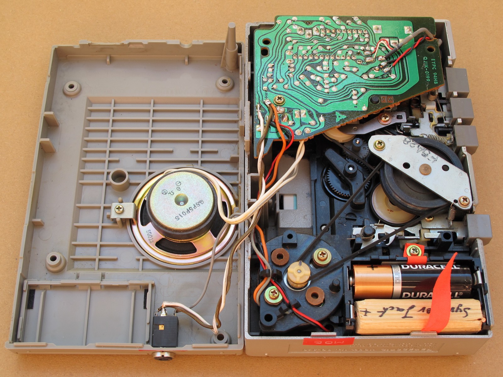
The first thing to think about: how and where should I install the mod? After I’ve opened the device, I made a fast analysis:
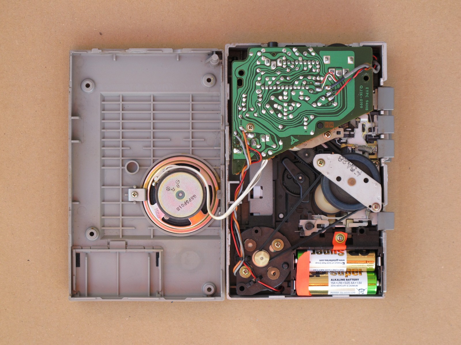
- a lot of moving parts in the middle with tight speaker fit – thats bad,
- an empty spaces under the PCB, where (with some planning and cutting) a small PCB or even potentiometer could fit,
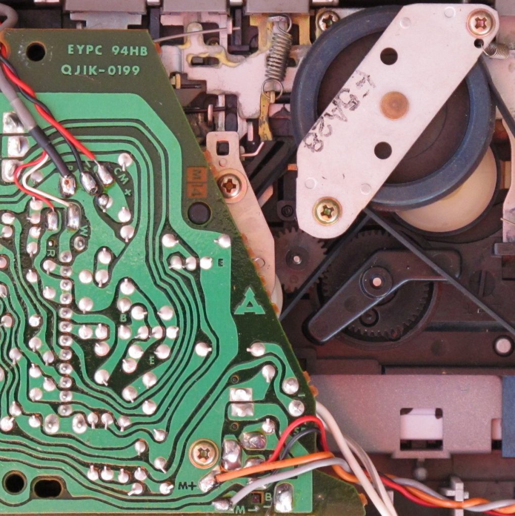
- motor is connected with easy to get black and red wires, solder points on the top of PCB – thats very good,
- lack of any build-in speed control – like trimmer on PCB – this would make modification a lot easier,
- 1 custom IC handles all the recorders features.
The next thing: how the device will be used? From the short interview I found out, that recorder will be played live on stage, which complicated the design (which I hoped to be piece of cake) in many ways. So, first of all: it should be reliable, and secondly: hard to damage. As the list of features began to grow, there was no other option, then make a modification as an external device. I had an idea to remove screw holders or speaker to add more space, but I wanted to keep the player as stock as possible. And also, this kind of “good looking” mechanical modifications cost a lot of time and I try to avoid them as often as I can.
The idea
I made a detailed sketch of initial idea. The one below is 100% real and will be worth $$$ one day. The amazing thing is how close to the finished device it acually is 🙂
The plan was to add a connector with switch to the device, so if the modification is disconnected, the internal routing is returned to its initial state. This way, it mod will fail (I hope not, but many things can happen), the only thing the user have to do is to plug it out.
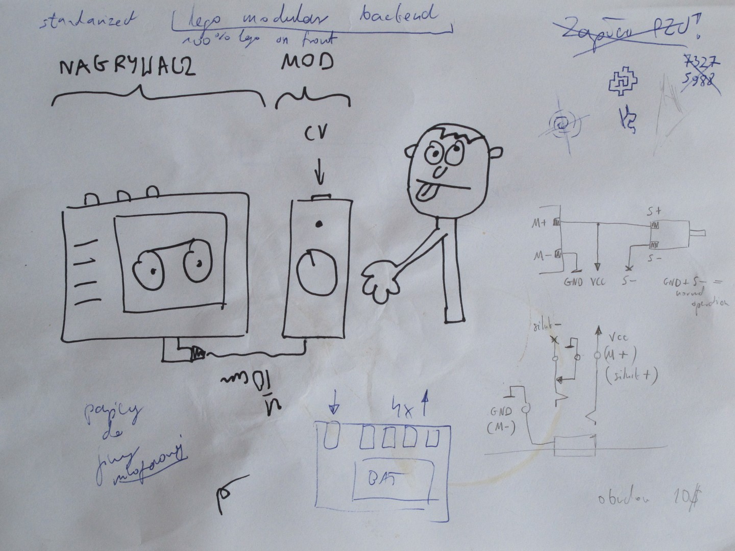
The mod (controller), build in a sturdy case, should have:
- knob – for controlling playback speed manually,
- CV input – for adding LFO modulation or some other undefined modular synth interaction,
- a LED for status indication (the first thing that should be added to any electronic device).
A very foggy idea began to grow.
One nasty problem
I spend so much time on this one, it is definitely worth mentioning. The really big problem you wouldn’t think of was… how to connect main unit and mod (or controller). Let me explain: it is obvious, it should not use any audio related socket, because of a possibility of erroneous connection I wanted to avoid. But the only connector with 3 (or more) ways and a switch, which could fit inside, was ironically, a stereo 3,5 mm jack. In theory, I could just use any 3 way connector and an external switch. But still jack was the smallest and only one fitting. (Later I’ve discovered a strange connector used in some HP printers I could use, but it was to late).
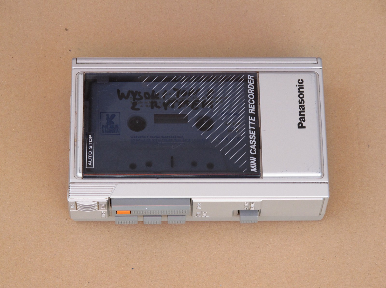
My biggest fear was someone will plug mono cable (shorting GND and VCC) and as you now, those are very popular in eurorack synth world. I did the only thing I could – minimized the risk of failure. The jack is installed only on the cassette recorders side, but on the controllers the connection is hard-wired. The other idea was to use some custom cable to connect both units together. But then I saw with my eyes of imagination how many times I would have to make this cable again, as it will be probably lost countless number of times. Additionally, the sticker on the recorder states: “MOD”. I hope this will be sufficient (and nobody will think it is an modulation input and injects LFO signal).
If you have a better idea how could I solve this one, please tell me, so I could avoid such strange solutions in the future. I mean the “jack thing”, not a piece of wood used as a battery replacement.
The circuit
A common techniqe of implementing DC motor speed control is a pulse width modulation (PWM). As I started looking for some details on its proper implementation, I found this article on cassette player hack. It was an inspiring read and helped me to refine a circuit design I had in mind. The assumptions for the electronics were:
- use some small, generic, microcontroller with:
- low power consumption
- ADC (minimum 2 inputs – for potentiometer and CV)
- timer with PWM option,
- add an CV input protection,
- use popular MOSFET transistor as output driver,
- take power supply from cassette recorder.
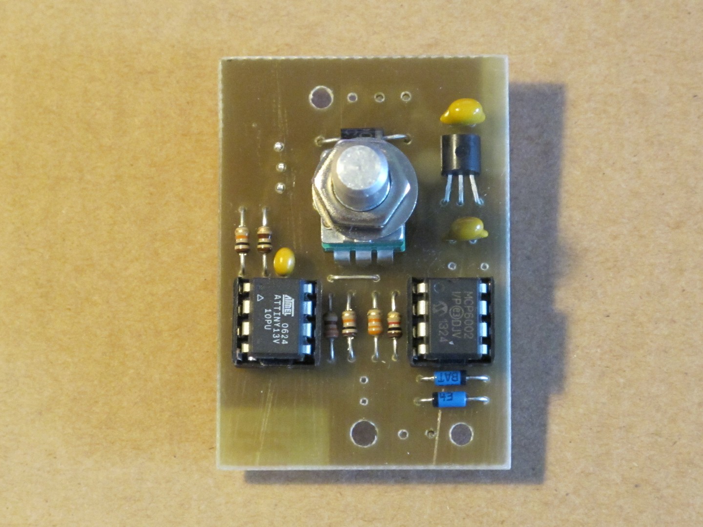
I decided to use ATTINY13V microcontroller & MCP6002 opamp combo, along with IRLZ24N MOSFET as switching element. As the power supply voltage was very unstable (from around 3,3 to almost 7 V), I’ve added an LDO voltage regulator (MCP1700-3002) for uC powering. It was time to move onto testboard.
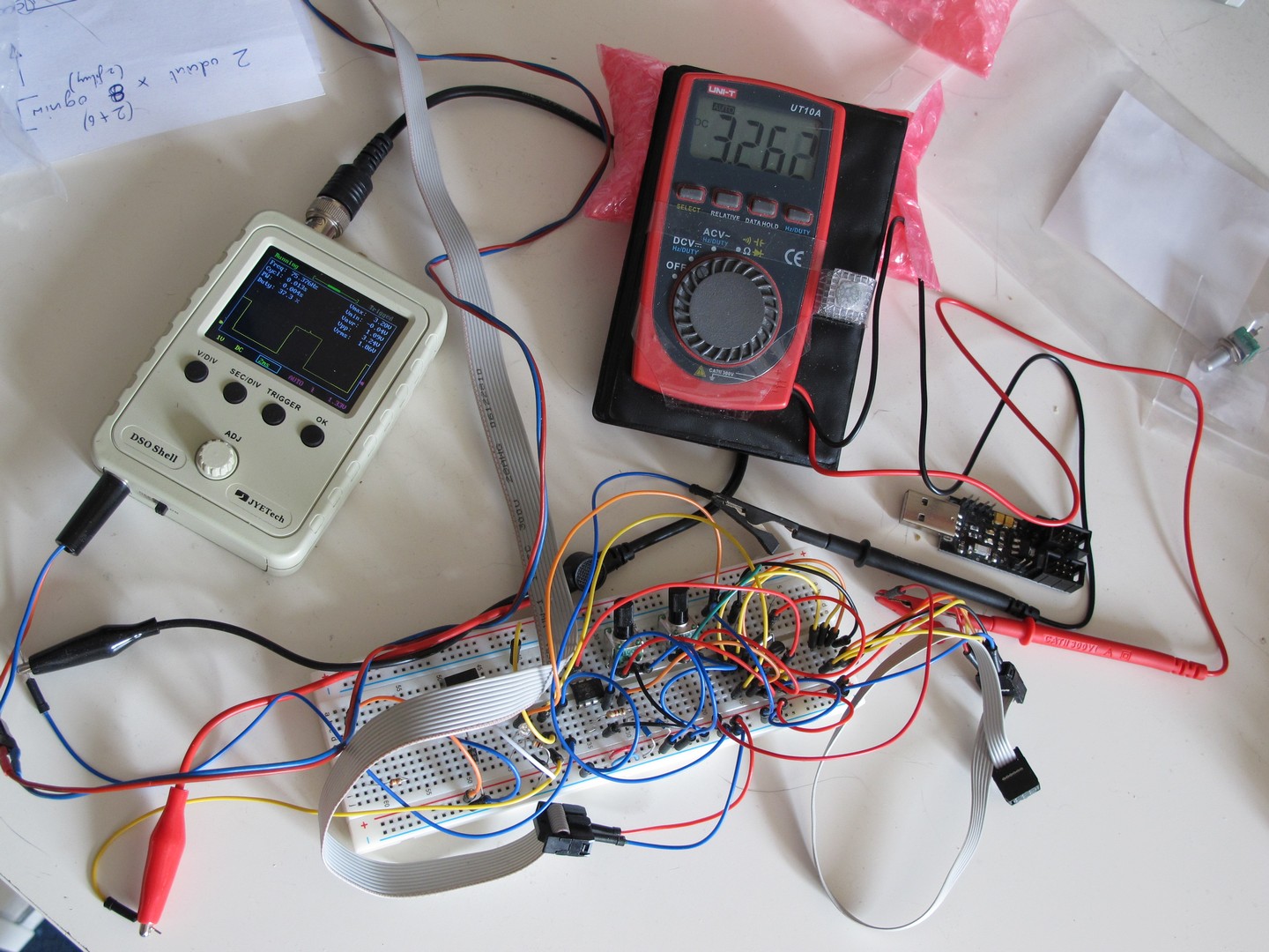
As I was going through some laboratory equipment shortage, I had to use DSO150 as oscilloscope and UNI-T UT10A as a meter. At least I had plenty of free space on desk my cat could (and did) utilize. Oscilloscope shows a typical PWM waveform (here with PW=37% @ 75 Hz), meter the input power suppy voltage from recorder (3,26 V regulated to 3,0 V, the charm of LDO).
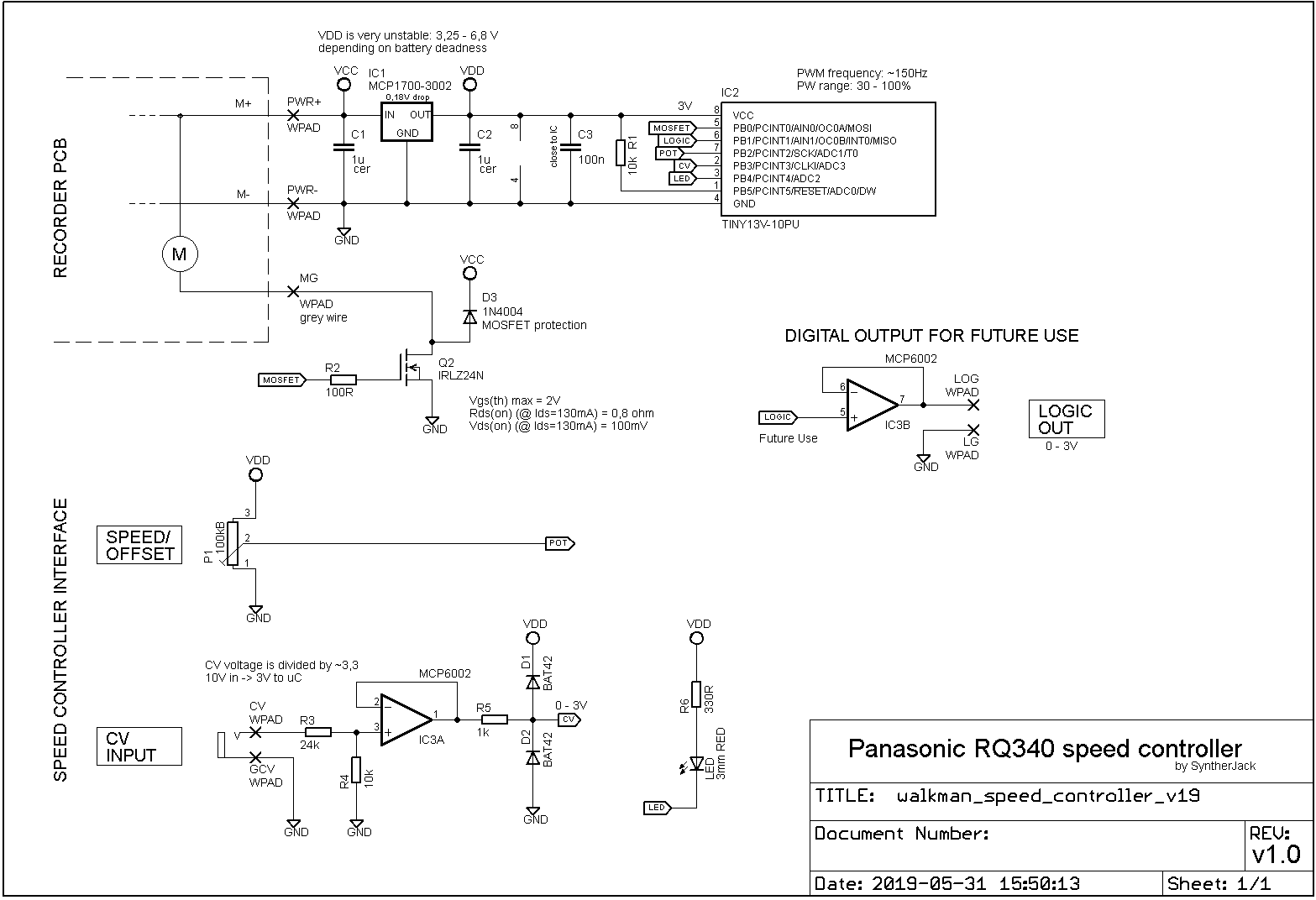
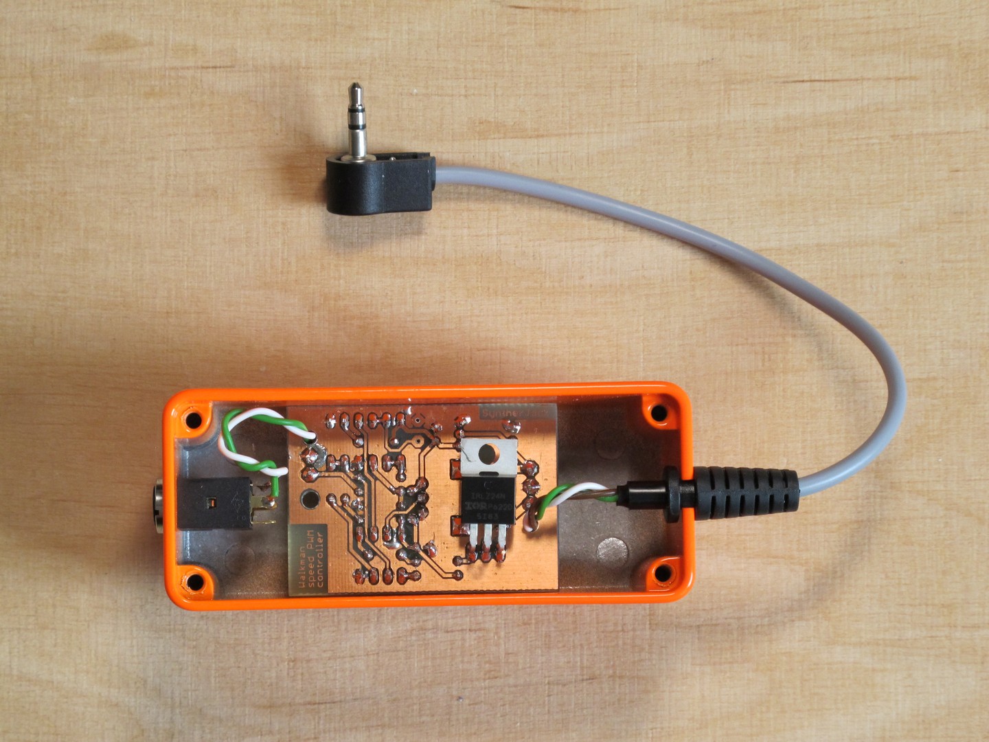
How it works? The recorder (top left) outputs three signals:
- PWR+ (M+: positive power supply to motor from PCB) – used as power supply (VCC) in controller circuit,
- PWR- (M-: originally an negative power supply to motor from recorders PCB, disconnected when mod is connected) – used as reference (GND) in controller circuit,
- MG (motor’s negative power supply solder point) – PWM signal is fed here directly.
The VCC is regulated via MCP1700-3002 (IC1) to around 3 V and serves as ATTINY13V microcontrollers power supply. C1 and C2 (1u) are needed for correct IC1 operation. R1 pulls up microcontrollers RESET signal to VCC to avoid incidential reset and C3 filters IC2 power supply (there is a lot of noise/spikes due to PWM). Microcontroler via its extremely complex firmware computes pulse width of a MOSFET driving signal, according to potentiometer shaft position (POT) and control voltage value (CV). The CV INPUT signal is divided by ~3,3 via R3/R4, then buffered by IC3A, finally clamped by R5/D1/D2. It is a bit an overkill protection, but I have no idea what my friend will fed into CV input. One unused opamp is left for the future and could be used f.e. as TRIGGER output if PLAY is pushed.
One thing is worth mentioning – in my case circuit works best with lowered cassete recorder suppy voltage, from 6 V (4x AA) to 4,5 V (3x AA). It just has wider speed control range and doesn’t affect maximum playback speed in a noticable way.
Update: Now I see I’ve made an error. Opamp is not protected against negative voltage that may occur on CV input. It looks like I’ve over engineered the protection – without an opamp it would serve better :/
The software
Of course, microcontroller is nothing without its firmware, let’s look at it in some details.
All the PWM is done in hardware via Timer0 in Phase Correct PWM Mode (I had a random polarity changes in Fast PWM Mode). I do not approve making any timing related software jobs running in loop with delay() function. The PWM frequency is set to ~75 Hz (half of Timer0 overflow frequency) and PW via OCR0A register.
The CV input voltage and potentiometers (working as input divider) output voltage are sampled with 75 Hz frequency and 8 bit resolution, then each channel values are summed (Avg1/2 variable), averaged and finally mixed together (Mix variable). With no CV signal applied, potentiometer acts as speed control, with CV signal, as offset adjustment. Just to get the idea what am I talking about, check a small, but most important, code part. The full code can be download here.
#define ADC_BUFFER_SIZE 8

// ADC interrupt service routine
// sampling rate: ~150 Hz, per 2 channels (~75 Hz per channel)
// averaging: 8 samples (11% of flash)
// ADMUX=0x21 - channel 1, ADMUX=0x23 - channel 3
interrupt [ADC_INT] void adc_isr(void)
{
    static uint8_t ADCData1[ADC_BUFFER_SIZE];
    static uint8_t ADCData2[ADC_BUFFER_SIZE];
    static uint16_t Avg1=0;
    static uint16_t Avg2=0;
    static uint8_t i1=0;
    static uint8_t i2=0;
    uint16_t Mix=0;
    uint8_t j;

    // get channel 1
    if(ADMUX==0x21)
    {
        Avg1=ADCH;
        ADCData1[i1]=ADCH;
        i1++;
        if (i1>(ADC_BUFFER_SIZE-1)) i1=0;
        for(j=0; j<=(ADC_BUFFER_SIZE-1); j++)
            Avg1+=ADCData1[j];
        ADMUX|=0x02; //set to read another channel in next int
    }
    // get channel 3
    else
    {
        Avg2=ADCH;
        ADCData2[i2]=ADCH;
        i2++;
        if (i2>(ADC_BUFFER_SIZE-1)) i2=0;
        for(j=0; j<=(ADC_BUFFER_SIZE-1); j++)
            Avg2+=ADCData2[j];
        ADMUX&=0xFD; //set to read another channel in next int
    }
    // PW below 30% is useless, motor stops
    // ADCtoPW is a lookup table;
    // converts 0-255 value to 77-255 range in a nonlinear way...
    // ...to make control over low speeds (PW < 60%) finer
    // add channels
    Mix=((Avg1 + Avg2) / ADC_BUFFER_SIZE);
    if(Mix>0x00FF) Mix=0xFF;
    OCR0A=ADCtoPW[Mix];
}
The most interesting part of the code is nonlinear conversion between Mix value and OCR0A (PW) value. Because the PW range corresponding to low recorder speeds (that’s where fun begins) was quite narrow, I decided it would be nice to have finer control here. As result, a bit more then half of ADC output (Mix) covers 30-58% PW, the rest 58%-100%. All the nonlinear conversion is done via ADCtoPW[] lookup table.
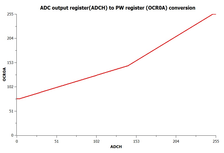
The knee point on the plot below is exactly at 58% of max. OCR0A and 56% max ADCH output. With pulse width lower then 28% the motor was stopping and even increasing it to 100% again did not cause any action. So, I’ve limited PW range to usable 30-100% range. The small dead zones around both curve ends ensure top and bottom PW value will be reached without any problems.
Enclosure and the PCB
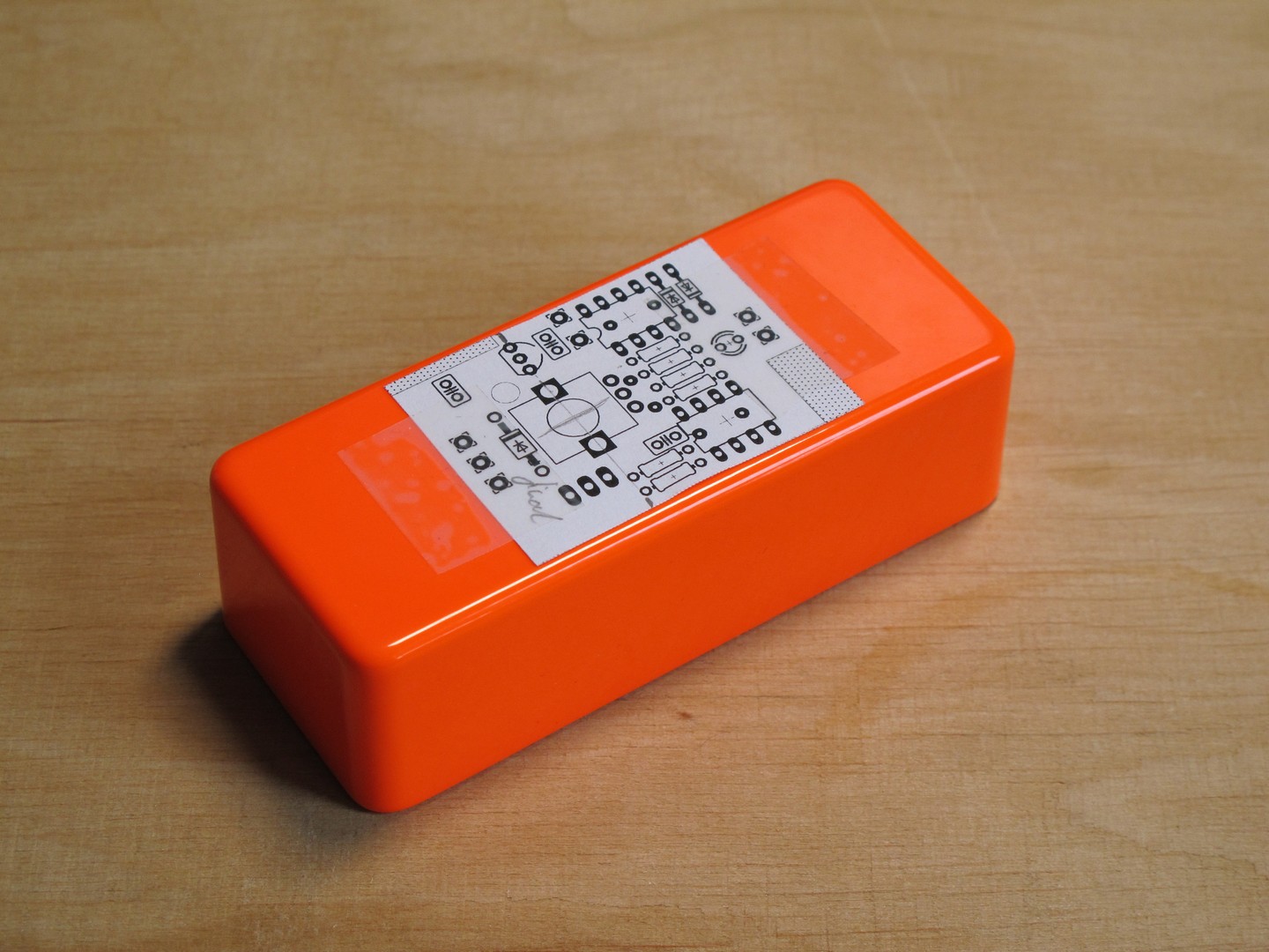
First enlosure, then PCB. In other case, you can end with the PCB that don’t fit the box of your dreams. As the designed circuit was very simple, I just couldn’t resist to use furiously orange small guitar effect box I found on Tayda (1590A Hammond style). And its color suits the recording button 🙂
As I wanted PCB to be attached directly to the box via potentiometer, the advanced placement tests were needed. And what is more important, I could use the PCB print as template for drilling – this way PCB would fix perfectly! The print was attached with Scotch Magic Tape – I find it very useful in DIY prototyping: transparent, easy to detach and you can write on it.
It was time to etch the PCB – one sided are a piece od cake with photopositive method. As always, I’ve used Bungard laminate with light-sensitive coating. It is a real time saver and PCB are perfect every time. I also found out they work great even 5 years after an expiration date (the only downfall is a glue on protective folic cover becomes very sticky and messy).
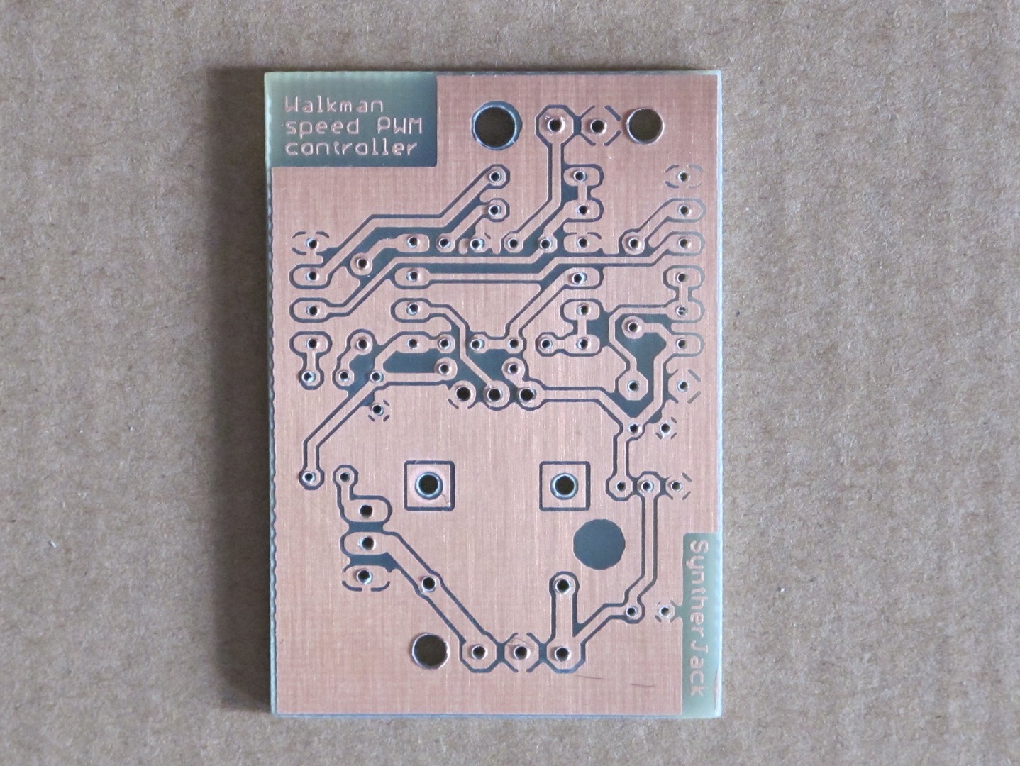
The ATTINY13V microcontroller was programmed on testboard, so no additional programming pin header are placed on PCB (I know it should be there, but this would make routing more hard, as the PCB is one-sided). The LED was not soldered yet, because its installation hight depended on how the PCB fitted into enclosure, which is hard to predict precisely. The round 3 mm holes near the PCB edges are for wire fixing (it will be visible better on the next photos).
I have drilled / filed all the necessary holes to fit potentiometer / LED on the top and strain relief / jack socket on side of the box. If you are courious what the strain relief is, that’s the black rubber thing at the end that does not allow the cable to bend excessively. The cable may look fragile, but it was designed for control in industrial applications and can stand a lot. The jack plug is Lumberg WKLS40 and a jack socket an polish gold plated version of QingPu WQP-PJ3410 (or Cliff FC681374V), but with uncomparable better quality (and higher price). It so great to have 2 technical cable and 4 electronic components shops in the range of 2 km from home.
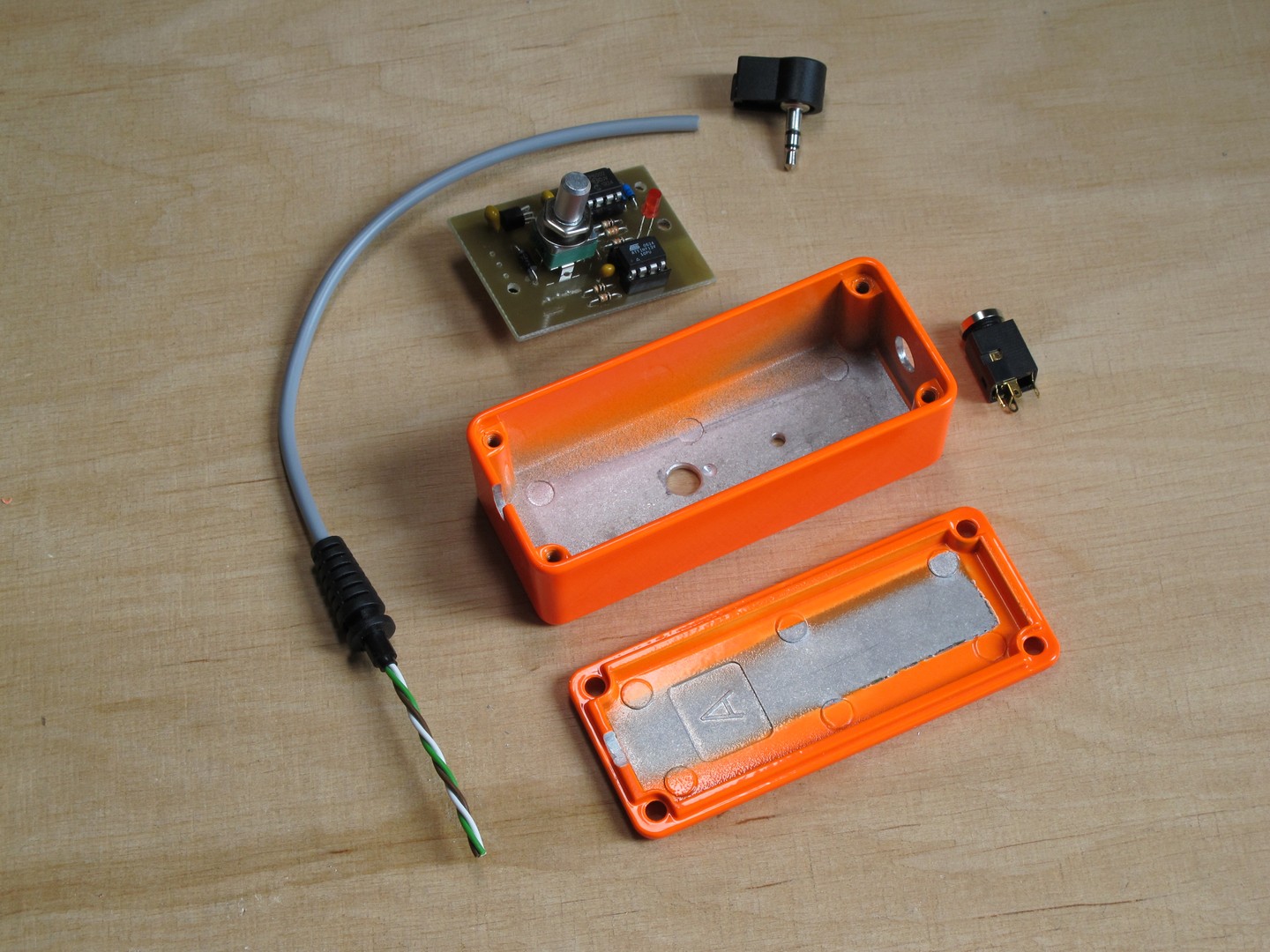
And this is how controller looks when assembled. Every part can be took out and repaired if needed. As you can see, both internal connection cables running from jack socket and cassette recorder (green / white / brown) are routed through small 3 mm holes in the PCB I mentioned before. This way they are additionally mechanically protected and believe me. those tiny holes makes a difference.
The grey control cable is secured in the hole with heat-shring tube. The tube is shrinked on the cable, then strain relief is slided on it. The hole grinded in the aluminum enclosure is so tight, it leans against the relief / tubing / insulation – this way the cable is strongly secured and impossible to move.
Right now, as I am writing, I’ve just got one thought – the cable from controller to recorder should be shielded. 75 Hz is quite low, but still in the audio range.
Final specs and demo
This is the end, time for last photo, specs and my usual poor demo (but it is still better then the last one). I must honestly say, it looks astonishing in reality. The camera just can’t reflect the amazing saturation of the color. Let me put it this way: in the dark, I my workshop, I am able to see only three things: my cats eyes and this box (the other cat is usually sleeping).
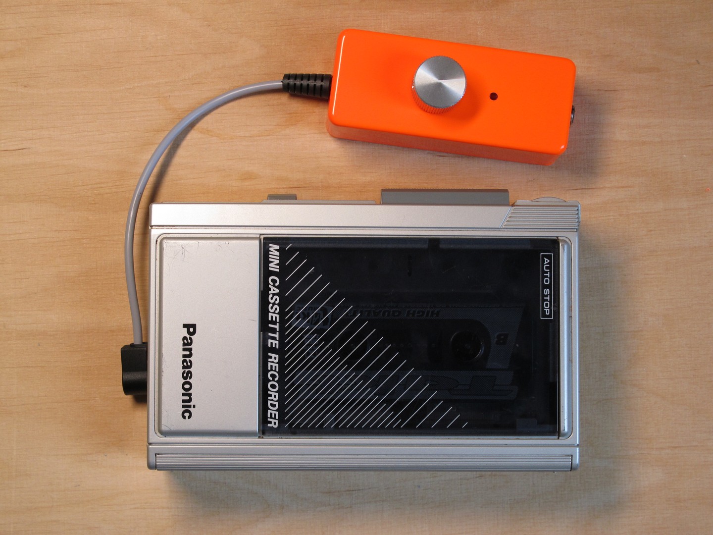
Specs of the cassette recorder speed controller:
- interface:
- SPEED knob – controls PW if CV signal is not connected, CV offset (or rather – initial PW value) – if connected,
- LED – indicator of the actual PW setting,
- CV signal input,
- PWM output to cassette recorders DC motor,
- electrical:
- PW range – 30% – 100%,
- PWM signal output level – depends on power supply,
- CV input range – 0 – 10V,
- power supply – from cassette recorder, preferred over 3,2 V,
- mechanical:
- size (without wire and strain relief): 95 x 47 x 39 mm,
- weight: 120 g.
Finally, the exciting demo, so you can get an idea how it works. One day a better one will come, when a proffessional will put hands on it.
If you want to use the code, just mention my name somewhere. Have fun with modding your own players!
Cheers
Jack
Hi, mate
Have you got a diy kit for this??
Thanks!
Great idea do you sell kits?
I would like to buy the speed controller gadget to use on my standard audiotape player by Sony. Do you sell these speed controllers to the public? If you do, how much are they? Could you send the device COD?
can you subscribe me to get the notice when this device for sell?
can you subscribe me to get the notice when this device become available for sell?
I think it will be never sell, as it is to much dependant on target device :/
Hi! i was wondering about the the voltage scaling and pitch. Can this implementation play a couple of octaves pitched with v/Oct scaling? Or, is it more arbitrary than that? i am wanting to use something like this to make a mono “mellotron-ish” eurorack module. Is there a way to implement a LUT?
Incredible project many thanks for sharing!
Thanks a lot for all this info, really from all post i found in internet this is what I’m using most. It promises will be very fun project ; )
Thanks Jack, you have new fan!