A story is really short: friend asked me to design a mixer/sync splitter which could fit between 2 3PO Pocket Operator cases from Dich Studios, so he can set the output level of each Operator separately. The cooperation was 100% remote and e-mail based, so it was very interesting experience for me.
The plan
I case you are not familiar with a 3PO case – it is an plexiglass enclosure holding exactly 3 Pocket Operator synths by Teenage Engineering. Objectives of the project were as follows:
- allows mixing of 6 POs audio outputs (3 connected from the bottom and 3 from the top),
- distributes SYNC signal across all POs, where one serves as clock master, other 5 POs are syncing to it,
- 2 inputs for other portable mono synths (Bastl Instruments MicroGranny 2 and one more PO, just in case),
- additional input for mixer chaining,
- all audio sources (8 in total – 6 POs and 2 additional) should have separated volume controls, so you can tweak the output level of every synth f.e. during live session,
- battery operated, low power consumption,
- dimensions matching original Dich Studios case.
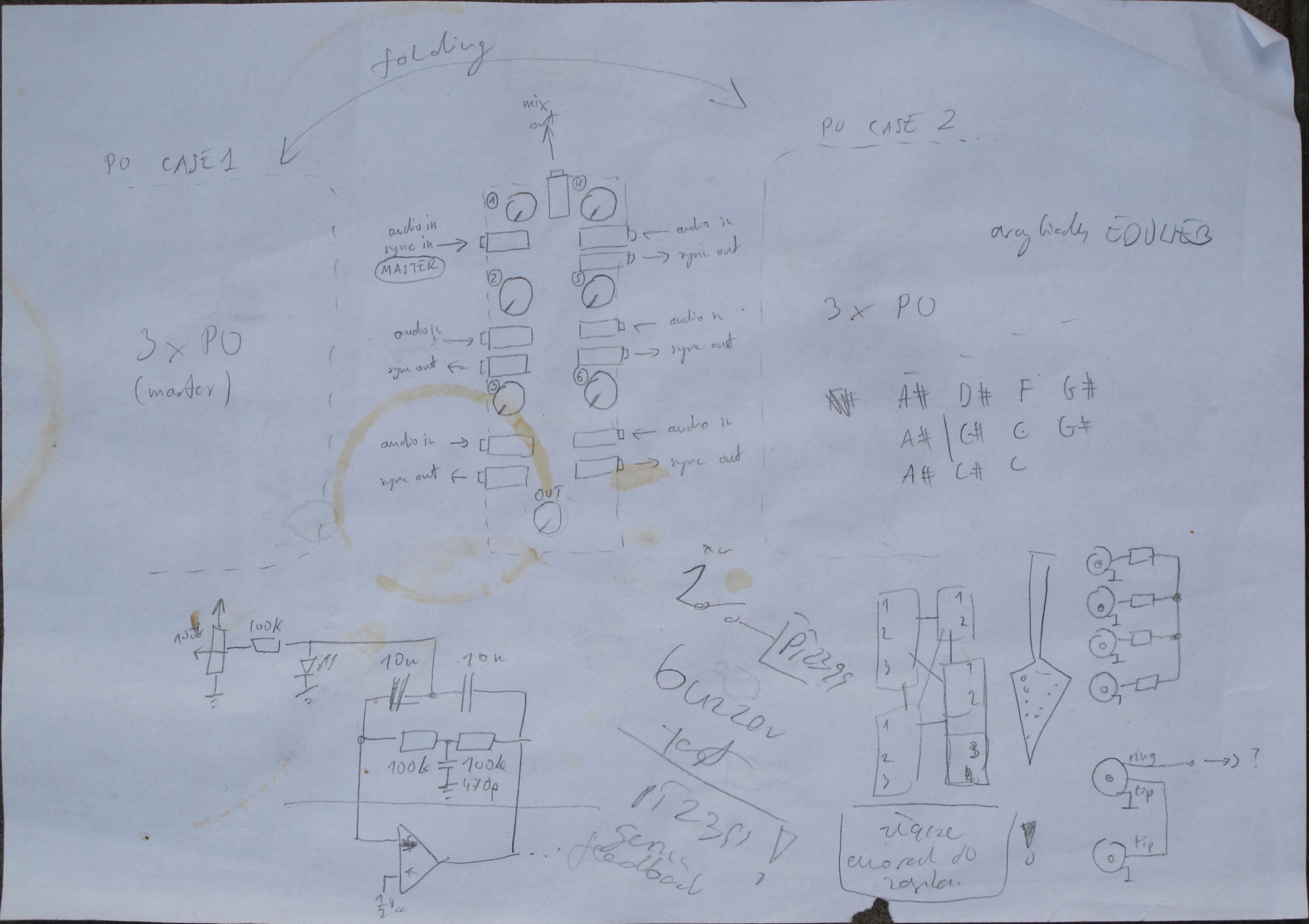
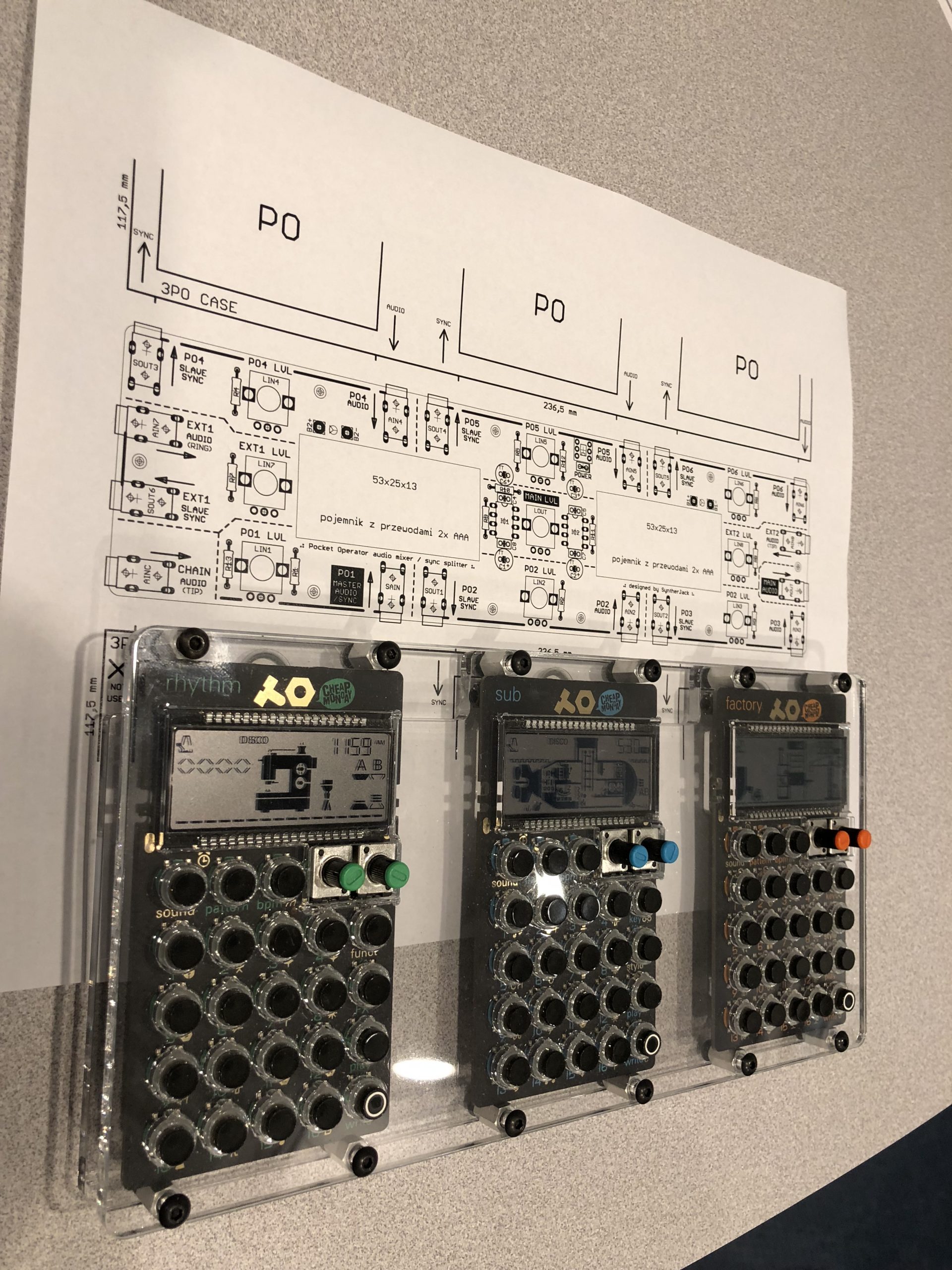
This is my first sketch, with only 6 inputs. You see where I am going to.
The electrical
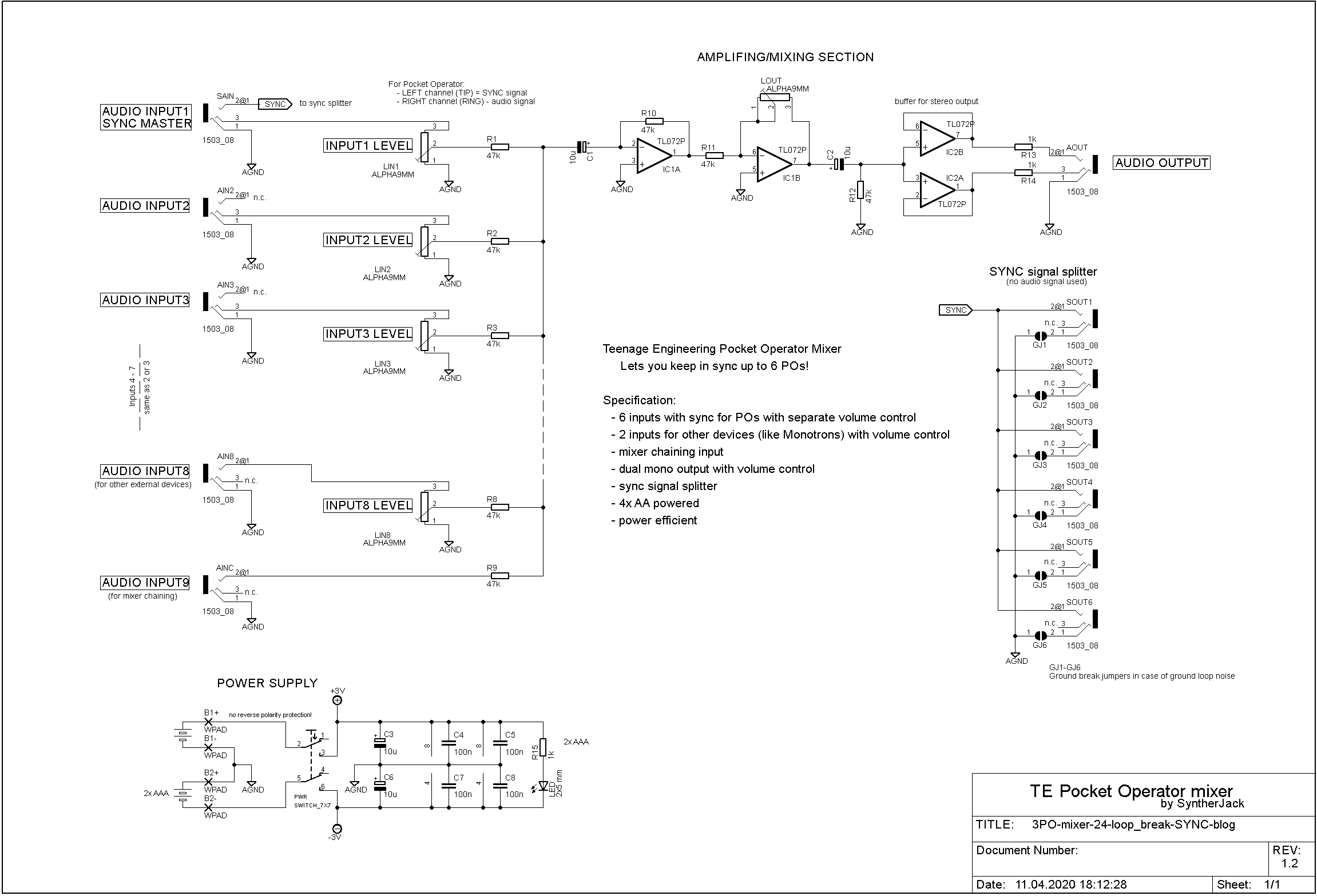
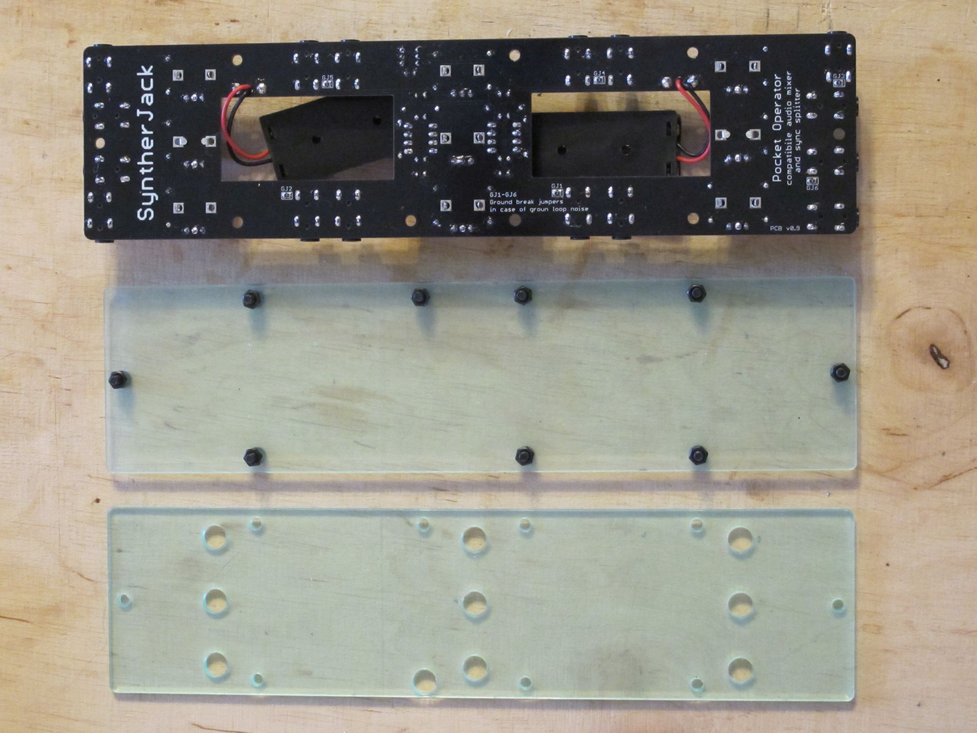
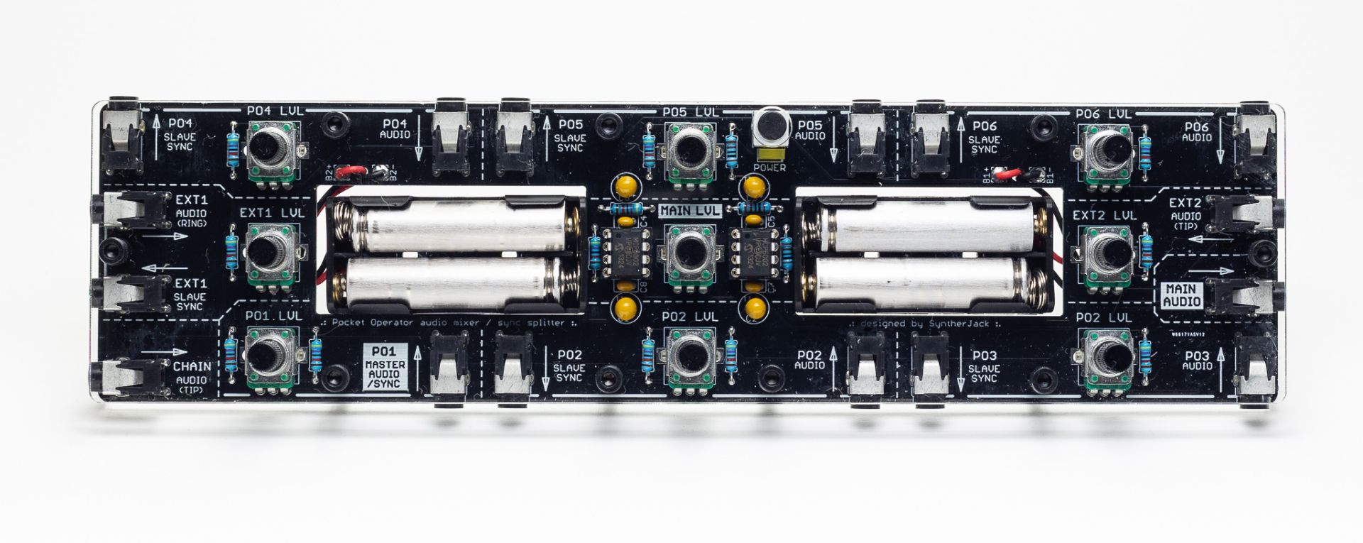
Few pots, some op amps, tons of jacks – usual mixer. It is mostly based on my 4sum design, with additional output buffer and SYNC signal splitter. To get the thing simpler, mixer is powered by 4xAAA resulting in symmetric +/-3V supply voltages (therefore I used MCP6002 instead of common TL072). As previously stated, one Pocket Operator serves as clock master for all other devices (AUDIO INPUT 1/SYNC MASTER input). In case of any ground loop problems, you can break it via GJ1-6.
The electrical design was the easier part.
The mechanical
Dimensions of the original Dich Studios 3PO case are: 9 and 5/16” wide, 4 and 5/8” deep, and 7/8” tall (those were sent by a friend). 7/8” tall is around 22 mm, and with 3 mm plexiglass covers it gives 16 mm for batteries and populated PCB. As the 12 mm is lowest what you can get with 2xAAA holder, I decided my mixer high will be ~18 mm high (without screws).
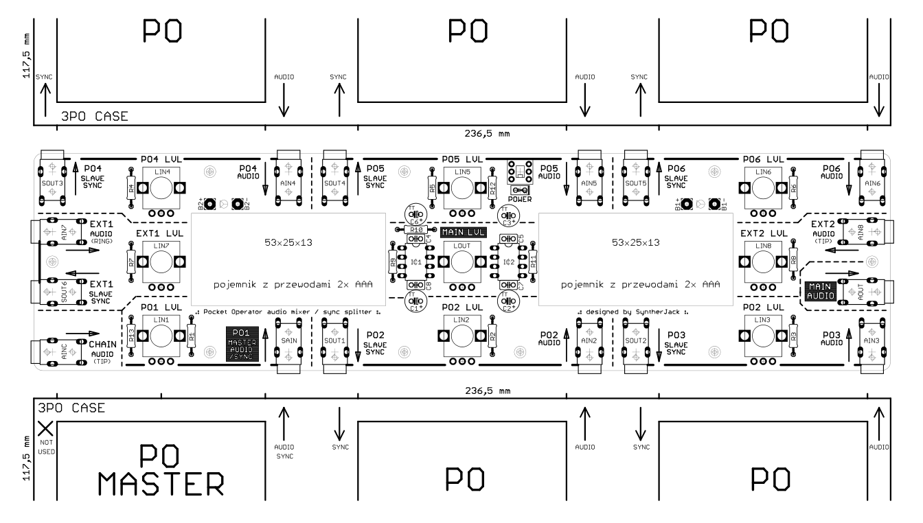
I’ve loaded measurements (along with Pocket Operators positions) into PCB design software to get the reference for jack sockets placements and overall PCB size. The wide was set by the 3PO case – 236,5 mm. The minimum deep was limited by 2x AAA battery holders and jack sockets size – 60 mm was the lowest reasonable (about half of the 3PO case, which is 117,5 mm).
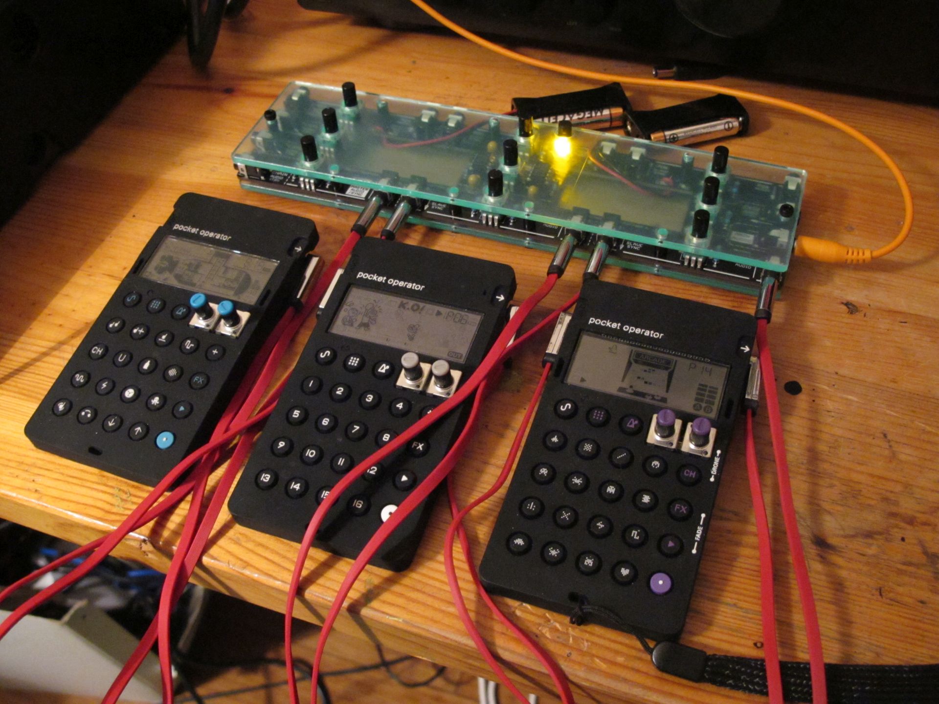
I had a small problem with the on/off switch placement. It just didn’t want to fit anywhere in my perfectly symmetrical design. Finally, the switch replaces one of the spacers and aligns with other screws. Mechanically not perfect, but ecstatically fine. As a great blue LEDs hater, I paired it with warm yellow one.
On the other side of the World, at 11:59 AM or 5:30 PM, the design was printed and checked if it completes the triple Pocket Operator case. It did.
The build
Device is a typical “sandwich” – PCB closed with a plexiglass panels. PCB was manufactured in China by PCBWay, the plexiglass sourced and laser cut in Poland. All passive components from Tayda Electronics, Thailand.
As the PCB is wide and flexible, therefore I used 9 spacers to keep everything stiff and in place. I didn’t want to use standard steel (silver) as I wanted to keep mixer black-themed. Finally, from the bottom side of the PCB, nuts are used as spacers, as I couldn’t get 2 mm ones. From the top, I decided to sleek, 8 mm round black anodized aluminum. Expensive, but beautiful.
All mixer sections are clearly marked. The level control for each Pocket Operator is placed close to it, so operation of the mixer is very intuitive. The main level control sits in the middle. Clock master PO is meant to be connected as the bottom left (MASTER AUDIO/SYNC input) – from there clock signal is distributed to other 5 Pocket Operators via SLAVE SYNC outputs.
Tests
It was quite a challenge to get some Pocket Operators to test the mixer. The best I could do was 3 :/ Of course, to fit with two 3PO cases, the jack audio cables must be shorter.
And that’s all folks. Friend is happy, mixer works as intended.
Cheers
Jack