
Resonance mod, LFO to cutoff modulation mod, if you are into Monotron Delay modding you have probably done it or at least know it exists. I wanted to go step further (and keep Monotrons sexy size). Introducing: Monotron Delay Implant!
What is implant? It is an additional mini PCB, containing opamp and some passive stuff necessary to perform more advanced modifications. What implant does?
- adds second waveform for VCO – squarewave with pulse width controlled by LFO; modulation depth is fixed (50 – 75 %),
- LFO can modulate cutoff frequency of a filter, pitch of VCO or pulse width of the VCO,
- LFO can be used as modulator or routed to filters input and act as separate generator for super fat drones, of for low frequency filter excitation.
The circuit is very simple. IC1B acts as comparator – it compares saw waveform level from VCO with (a little bit tuned via R1-R4) signal from LFO, resulting in square waveform with variable pulse width on IC pin 7. R5/6 matches levels between square and saw waves. IC1A amplifies signal form LFO and removes DC component to match filters input. Resiststors (47k and 4k7) in cutoff/pitch modulation paths are setting maximum modulation range. Thats all. Circuit have some unexpedted behaviour due to its simplicity, but you can use it in creative way.
edit 7.05.2017:
I found the “unexpected behaviour / random FX” cause – IC1A input is not connected if “LFO as modulator” position is chosen. 100k to GND on “+” input should solve it.
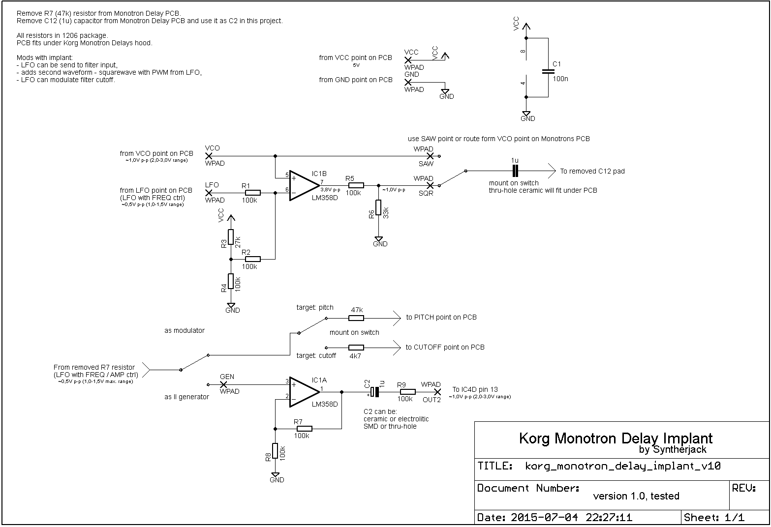
The only components you have to remove form original Monotron Delay PCB are R7 resistor and C12 capacitor (it is used later on implant PCB). You can find them here:
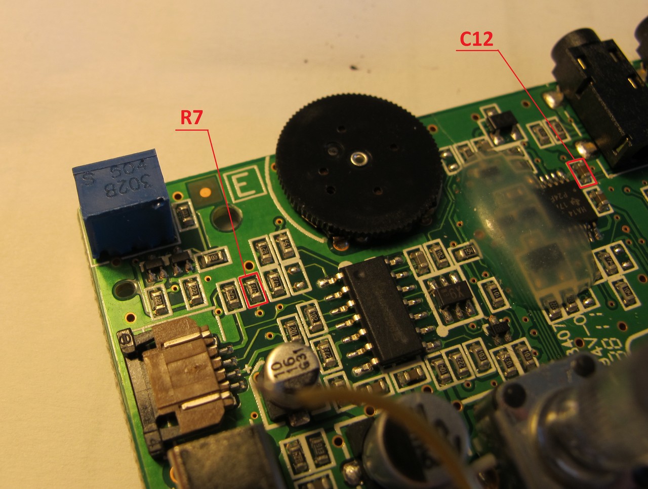
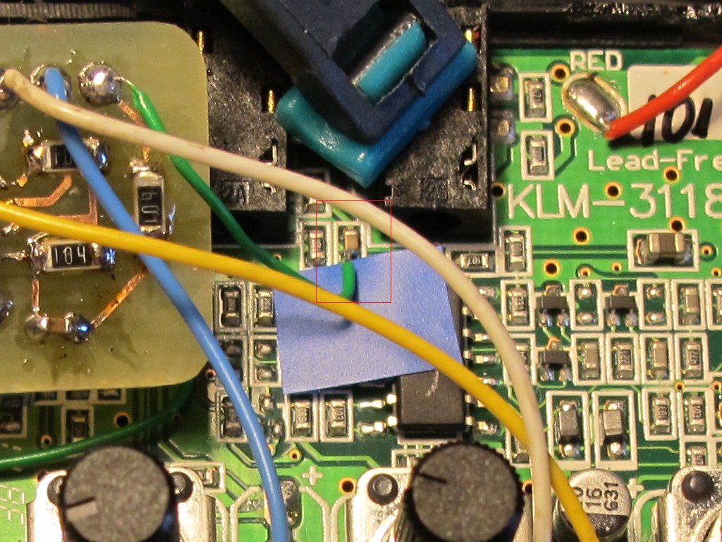
The connections from R7 and C12 pads to implant PCB looks like this. Is quite a delicate job.
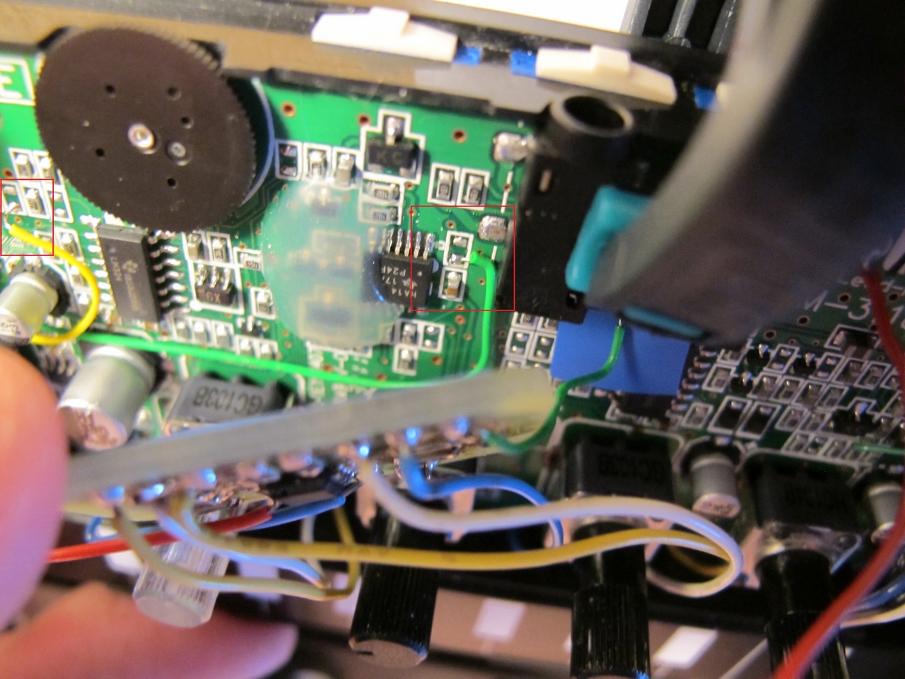
IC4 pin 13 is hard to get, it is more easy to solder to C15 (1uF) near it. I have covered a part of PCB with tape to make shure the will be no shortcut.
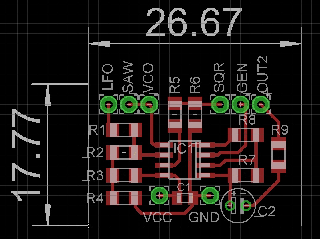
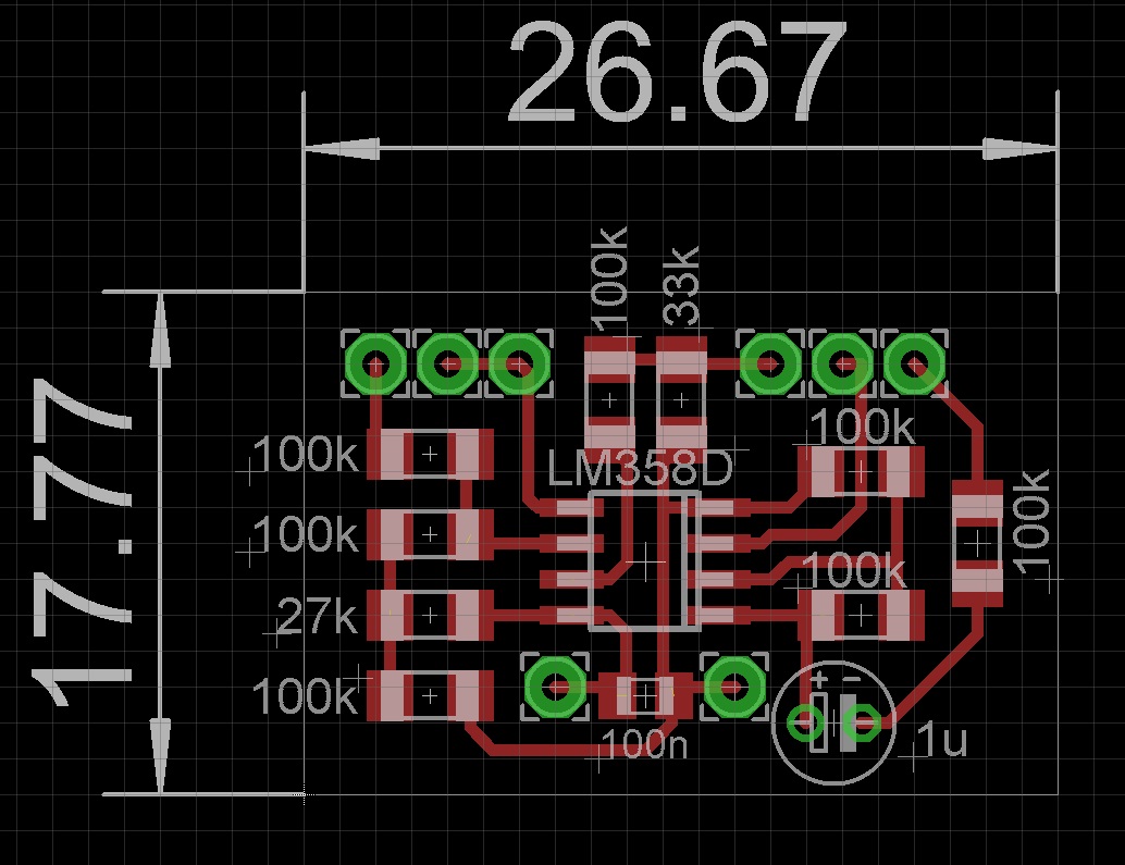
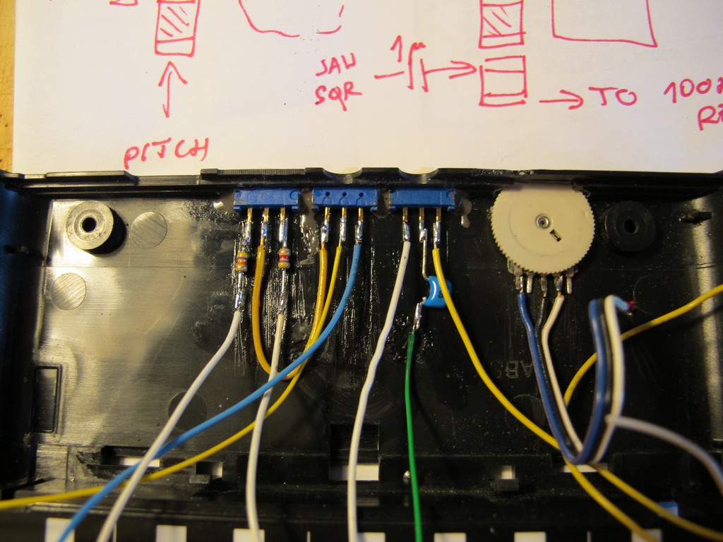
The implant resistors PCB with parts names and values. Notice there are still some parts to solder near to switches on Monotrons back (4k7 and 47k resistors, 1uF capacitor – marked on schematics).
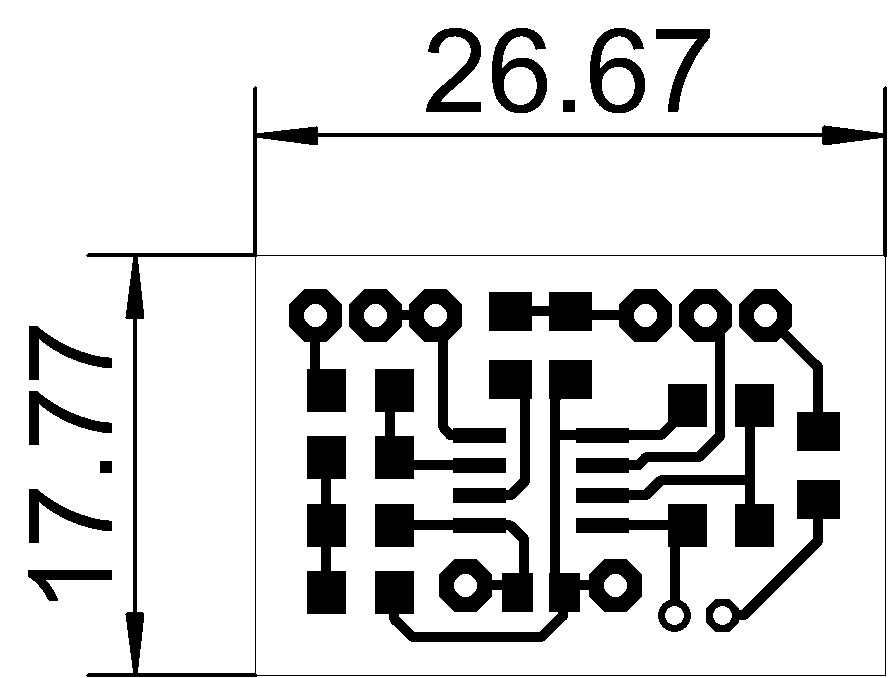
And finally, the Implants PCB. Resolution in 600 dpi. All resistors are in 1206, one capacitor in 0805, opamp in SO8. The 1uF thru-hole can be replaced by the one desoldered from original Monotrons Delay PCB.
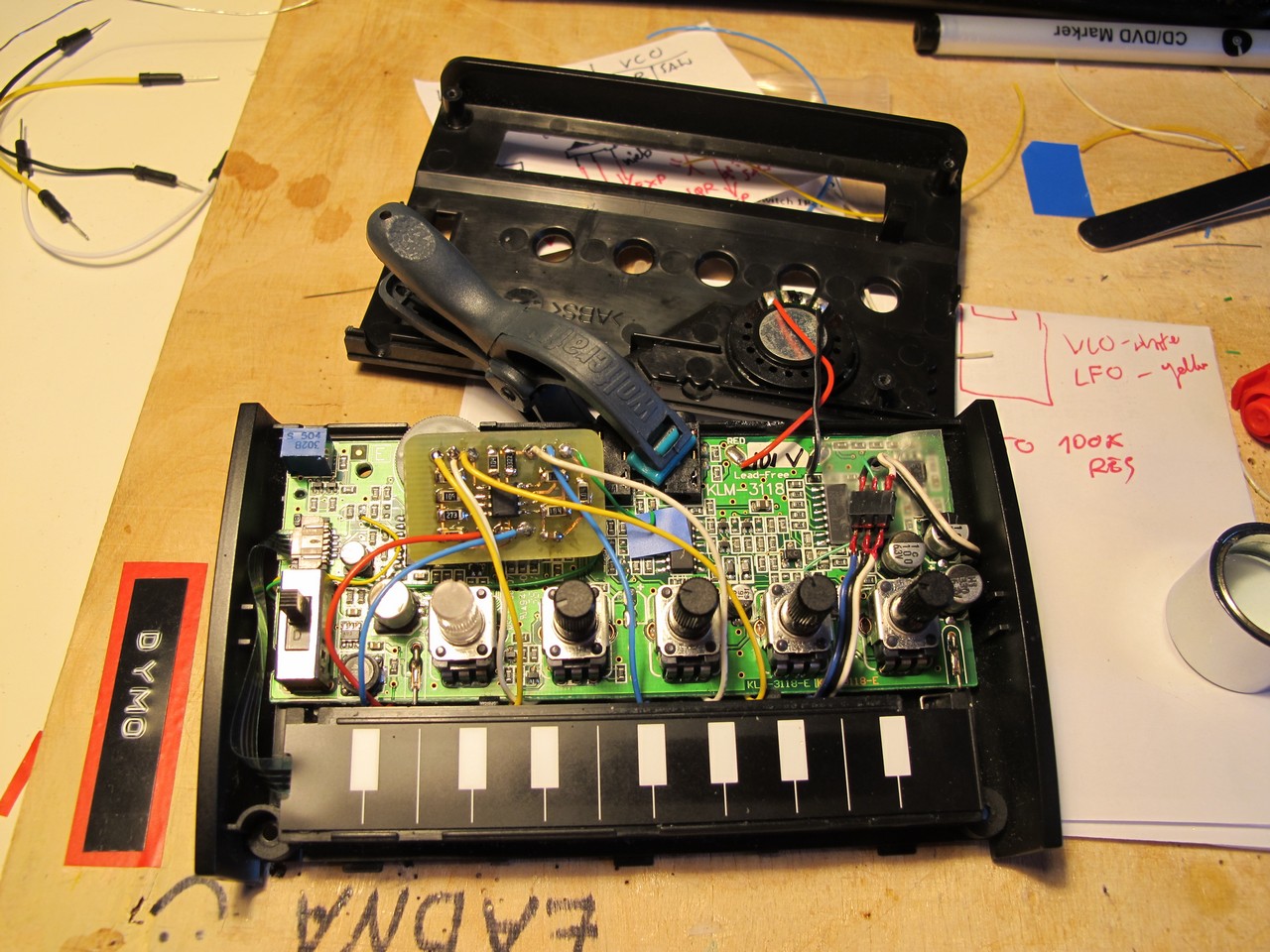
All additional switches and pots are hidden on the Monotrons back. The slide switch is EXCEL CELL ELECTRONIC, Mini Slide Switch 1P2T Through Hole 0.2A 24VDC, bought @ http://www.taydaelectronics.com, the filters resonance potentiometer was torn out of old CD-ROM (volume control), then grinded to make it thinner. This way Monotrol looks like a stock device.
Notice parts near to switches – 4k7 and 47k resistors and 1uF capacitor.
This is demo of my modified Korg Monotron Delay. Five mods were preformed on this particular unit:
- resonance mod (as described on: http://picsynth.000space.com),
- implant mod (3 mods in 1),
- break out connector (does not any sound, but was very helpful when modding).
It can make very unexpected sounds and yes, it is noisy, but in a good way. My cat loves it!
Jack
Do you have any pics for sale / spare?
Is it possible to add CV control to the Delay with a small 3.5mm jack plug while keeping the form factor of the original unit? Many thanks..Kevin
Yes, it is possible and shouldn’t be very difficult. There are many examples in the net how to add CV to PT2399 delay circuit. You may look at Synthrotek Echo, MFOS Echo Rockit, Echo Base v2 or Jenny Greenteeth for some examples of delay time modulation solutions. Cheers!