I had a lot of questions about a black box I use in almost every drum synthersizer demo. This device is just a simple 555 trigger generator, very useful in everyday synth DIY.
Why?
The question is: what advantage it has over a function generator?
- first of all, it is very handy – I keep it in my drawer with battery and Jack cable in and ready to action; it will generate trigger before I even find BNC for laboratory function generator,
- output voltage range is safe for modular use (7 V maximum) – my other generators have 20 V p-p output, so I have to check it (and offset) before turning on; this one here is no-brainer,
- has pulse width (PW) setting – not very popular control in cheapest function generators,
- runs at very low frequency (many generator I used worked down to 1 Hz only),
- if LED blinks, trigger is generated – no menu diving, all you see is what you get,
- even if you fry it, replacement parts cost nothing.
How do I use it?
- durning the first run, to check if the drum module works,
- how drum synth responds to different trigger pulse widths and levels – is there a retrigger or loss in sound fatness.
The schematic
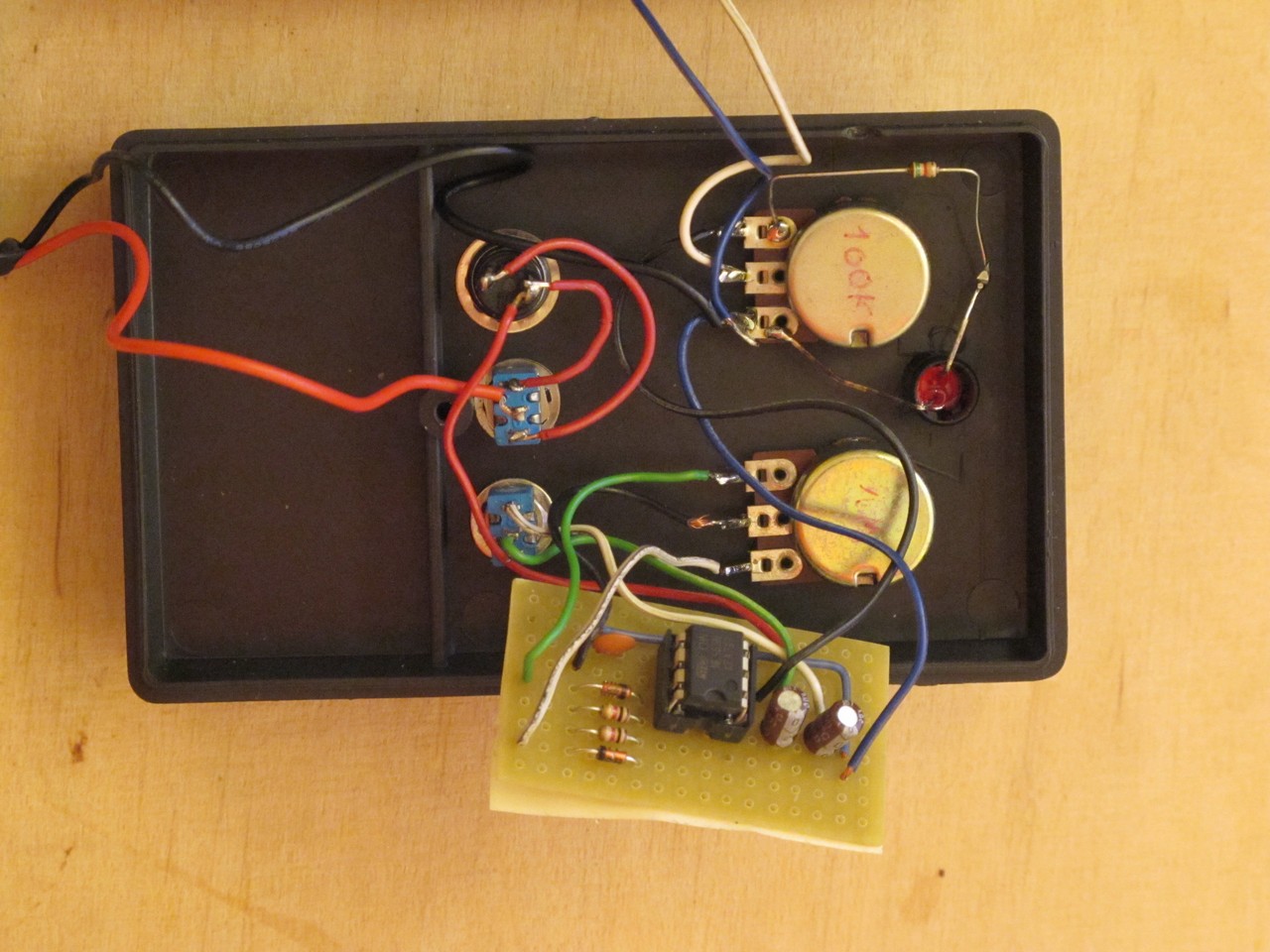
The device is based on 555 in constant frequency pulse width controller application, used often for LED brightness or DC motor speed control. Because it is so simple, you can build it on breadboard in minutes (or even solder components directly to front panel potentiometers / switches / jacks).
There are 2 potentiometers (for pulse width (PW) and output LEVEL) and 3 switches (power on, 1-shot generation and frequency (FREQ)). Jack output is very handy as you can use standard audio cables.
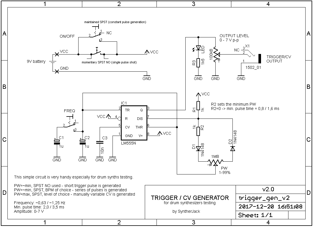
C1/C2 are timing capacitors and set a generator frequency to around 1,25 Hz for 2 uF (C1||C2 – FREQ switch closed) and 0,63 Hz for 1uF (only C2 connected – FREQ switch opened). D1, R1, R2 and part of PW pot sets the charge path. D1, rest of PW sets the discharge path for C1/C2 capacitors. R2 sets the minimum positive pulse time to over 2,0 / 3,5 ms depending on FREQ switch position. R3 with LED gives you a visual feedback about current PW and FREQ settings. The LED current is set to ~3 mA. LEVEL potentiometer sets the amplitude of the generated signal, from 0 V to around 7 V (assuming circuit is powered from 9 V battery). Finally, two ON/OFF switches let you choose the triggering method – maintained gives you a constant waveform generation, momentary (usually) a single pulse shot.
All parts are popular and easy to source, you should be able to build one way below 5 euro in less then 1 hour.
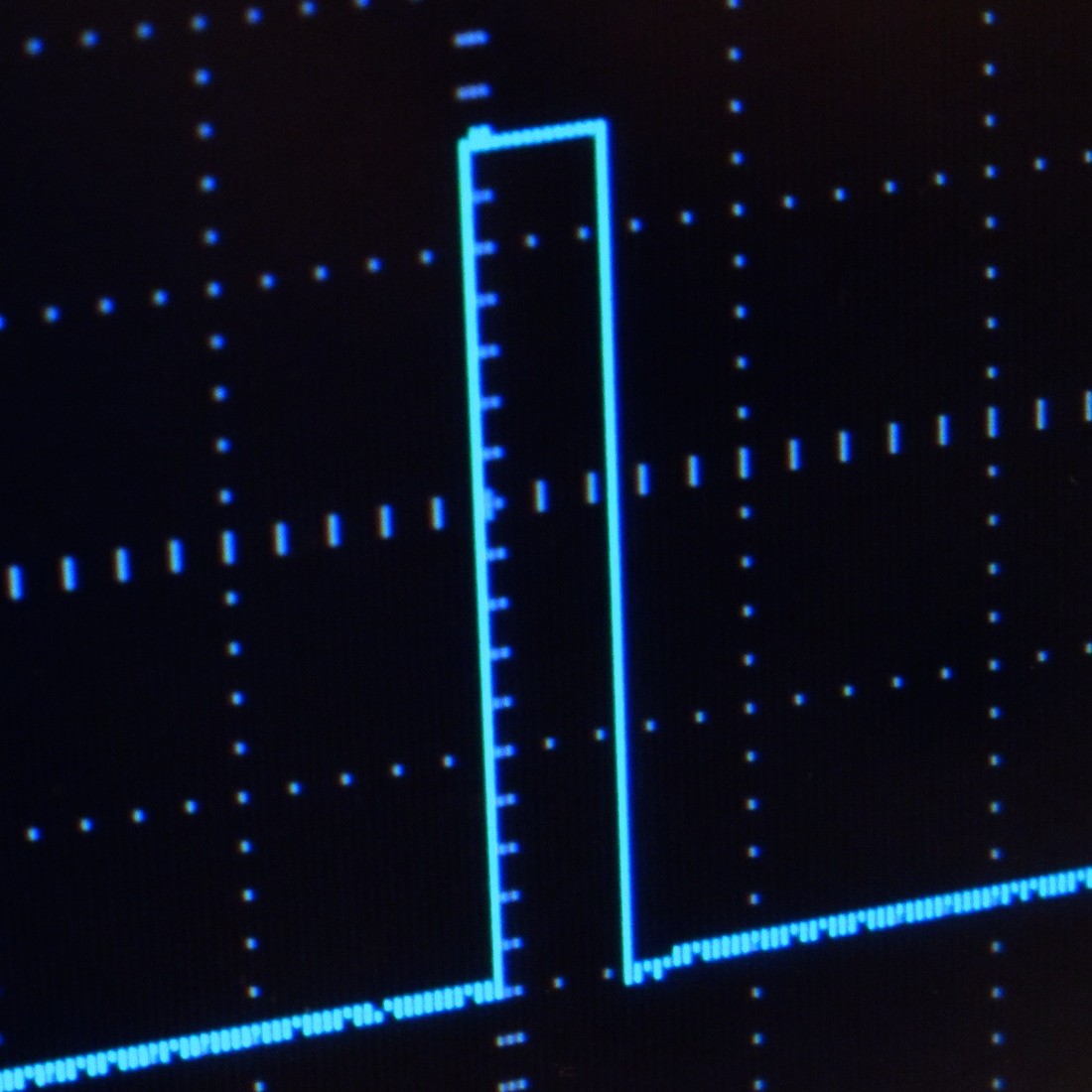
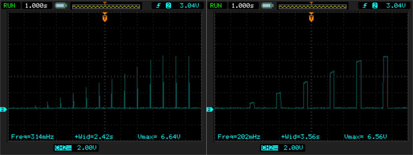
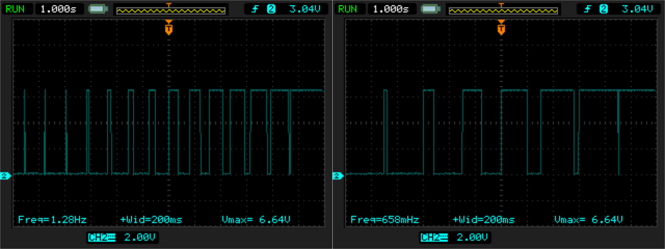
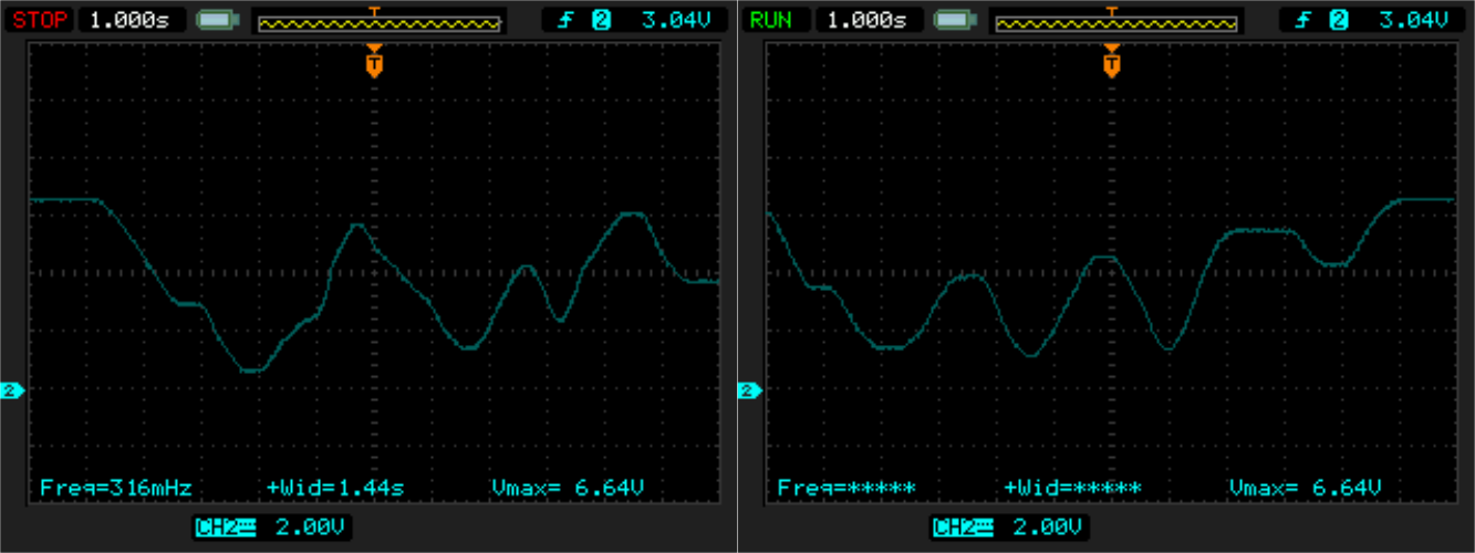
Waveforms
Squarewaves, mostly. Oscilloscope screenshoots shows all you can get from this device.
My awful build
It was one of my first synth-related DIY and experience with front panel design. Everyone started somehow :/
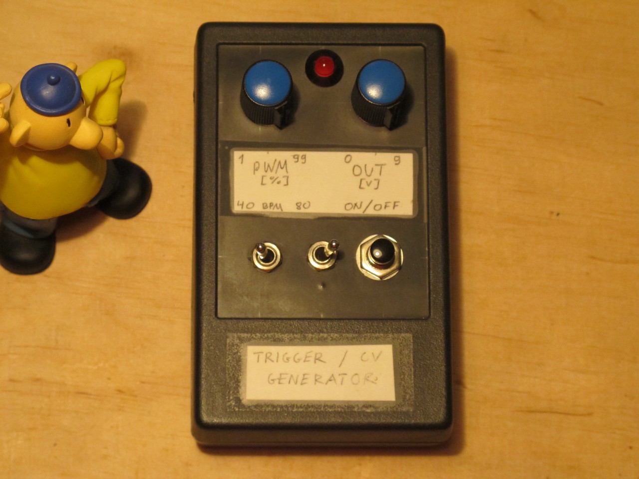
As you see, some markings are wrong:
- PW caption would be more accurate,
- generator goes from 1% to 100% (full on),
- maximum output level is 7 V (not 9 V),
- frequency is more like 50 / 100 BPM.
Everything else is ok 🙂
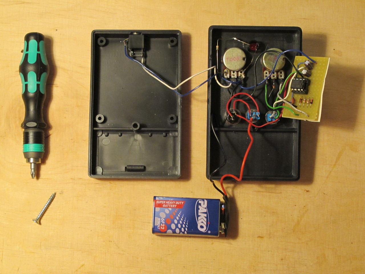
Jack socket is glued to enclosure. PCB is flying in the air. Nothing is protected against shortcut. And wires are way to long. You will do better for shure.
Considering the quality of parts I used, soldering and everything else, it is a big suprise it works over 5 years now. And I use it almost everyday! This little guy is very helpfull in DIY struggles, build one and you won’t regret it!
Cheers
Jack
Note:
I know “standard” trigger pulse for eurorack is 10 V, 10 ms. This generator gives 7 V, which is ok to make 99% of modules work.
Hey this is really cool little project. I am currently experimenting with piezos and I was thinking of booking one up in stead of the manual trigger. Any idea what I would need to change to integrate the piezo into the project? And would it be possible to use the velocity from the piezo trigger as well?
Thx already,
Sam
Also I am not getting rectangular pulses on my scope from this build.. the led seems to indicate that the pwm is working however what I get on my scope looks more like a segment of a sine wave with a complex timbre, nothing like the images you are getting. Any tips?
Hi there Jack, sweet project. Will this work with 12volts?
555 should handle 12 V, so the answer is: “yes”.
Just put one of these together. I thought I could build it all into a little Hammond case but couldn’t fit the 9v battery in under the switches and pots, so it’s in an outboard bracket. Ah, well.
I’ll probably be trying some of your drum engine circuits next — thanks for putting so much information online!
Perfect, I can choose the pulse width and the voltage. A perfect clock for my sequencer.
Is it possible to very the tempo ?
The thing is I did a baby sequencer with another clock but the pulse is to wide, 50%. Using your clock is perfect. I can make gate into a trigger but I can’t change the tempo. Any idea ?