Nobody reads labels
It must have happened, I just waited. When I was enjoying playing Bomberman in another part of the city, my girlfriend decided to hit some tunes on my old, trusted Microkorg. When I returned home, she seemed scared. I asked, what happened. She replied, something happened to my synthesizer, it behaves strangely. After power on, it just made a loud “pop” sound, then went silent. I looked at my desk, and there it was: 18 VAC (!) power supply from my Krautrock Phaser connected instead of 9 VDC (yes, everything was labelled and impossible to confuse). I was just standing in the middle of the room asking myself: “Why?”
The symptoms
After I pluged a correct 9 VDC wall-wart power supply, the LEDs were blinking in rather chaotic way. The LCD showed garbage. In few seconds all lights went out. After off/on cycle only two green “signal in” LEDs flashed. No key or potentiometer response, no sound. Girlfriend curled up in the corner. Cats have hidden.
The diagnosis
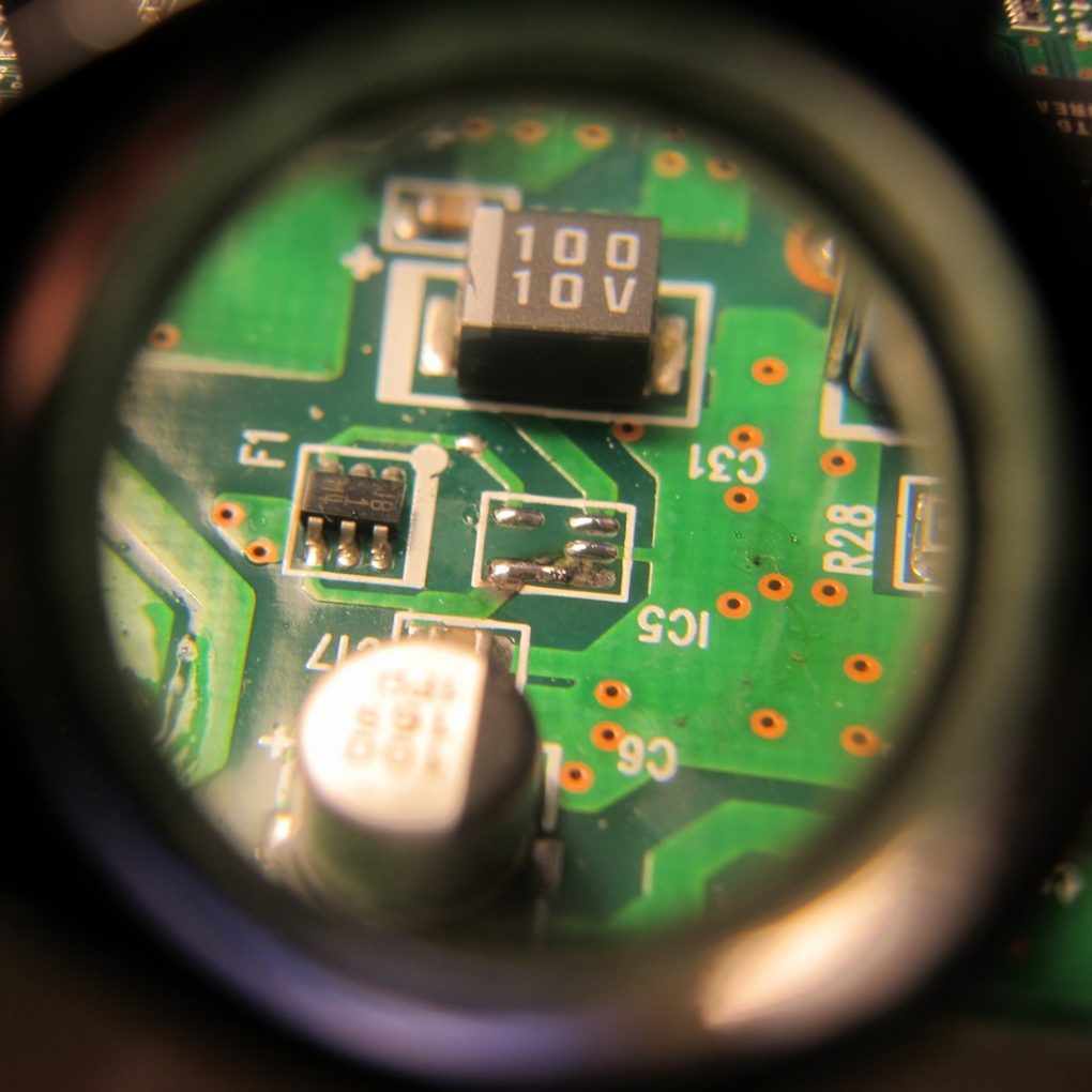
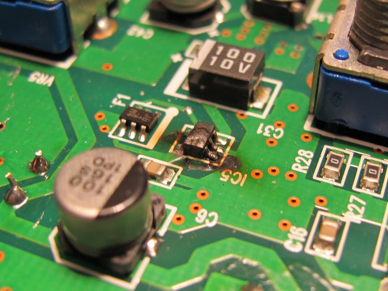
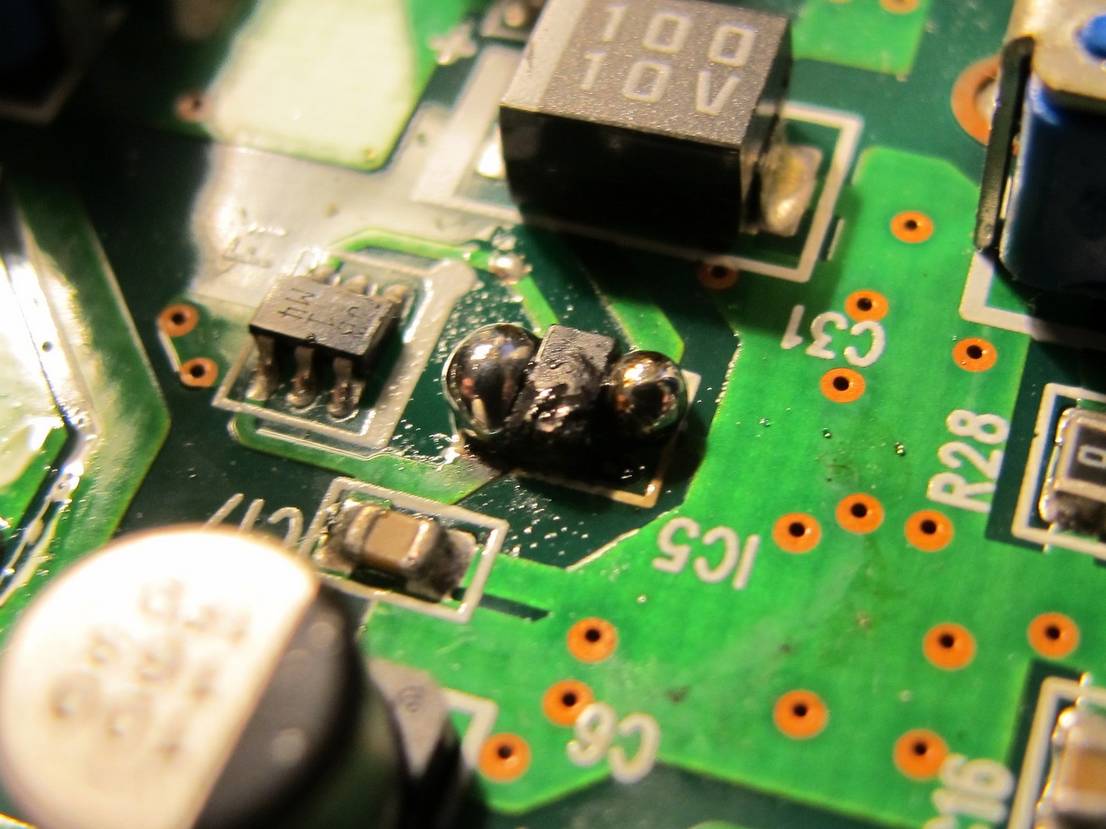
I searched some forums and found out it is a well known Microkorg feature – lack of overvoltage protection. The usual suspects were: fuse and switching power regulator controller IC. I opened the enlosure and got out the PCB. This is what I saw – the picture of despair and destruction.
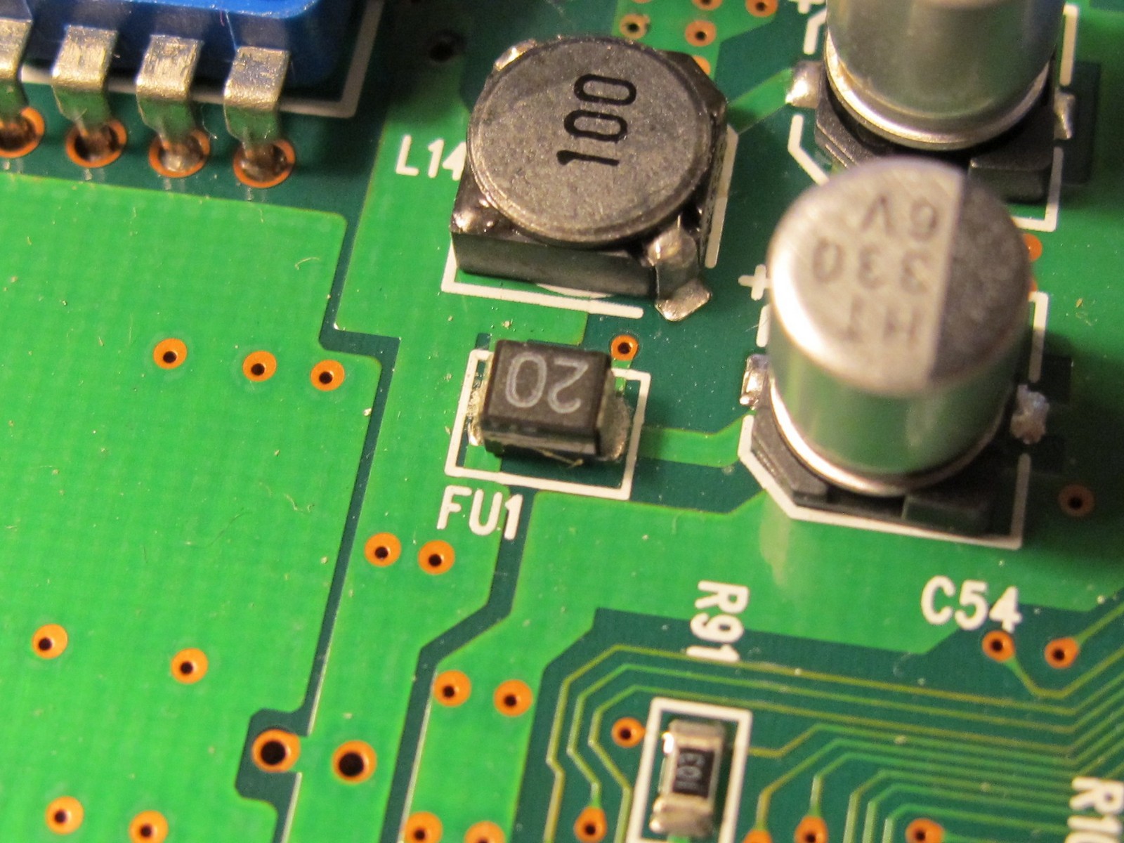
The second suspect, looking much less spectacular, was the FU1 fuse. After some measurements it became clear, it is also damaged (continuity test failed). But in this case, it was a good thing – the fuse fulfilled its task. The thought sprouted in my mind: maybe a DSP survived.
It was time to look for replacement parts. I was happy (in a strange way), because repair seemed to be simple.
The replacement parts
As it is a common Korg Microkorg failure, the replacement part numbers are well known (*). I bought them from eBay and Aliexpress:
- switching regulator controller (IC5) – S-8520F33MC (eBay, 1,7$ for 2 pieces),
- fuse (FU1) – CCP2E20TE, SMD in 1210 package, 72V, 2A (Aliexpress, ~4$ for 10 pieces).
(*) some people adviced to replace F1 -P-channel MOSFET (CPH6302). There was a big chance, it was also damaged, although in my case it was not a problem.
The repair
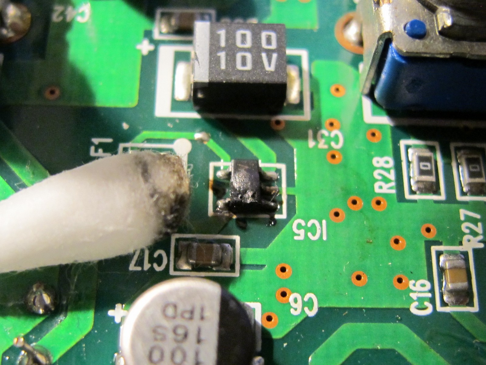
The first thing – cleaning. IC5 looked like it was literally boiling inside. It was hard to tell the condition of the PCB traces with so much soot and dirt. Fun fact: my girlfriend was so angry I always steal her swabs she bought a whole pack espacially for me!
Next, the desoldering! IC was in poor condition anyway, so the most easy way to get the rid of it was to “increase thermal mass of the joints” by creating big balls of solder (see photo below), then heating both sides of the IC alternately. After few fast left-right heating cycles the IC came off freely.
This looked really, really bad. One soldering pad was missing (it came out with the IC). But there was hope: if you look carefully, bottom left and bottom right pad seemed like they were once connected.
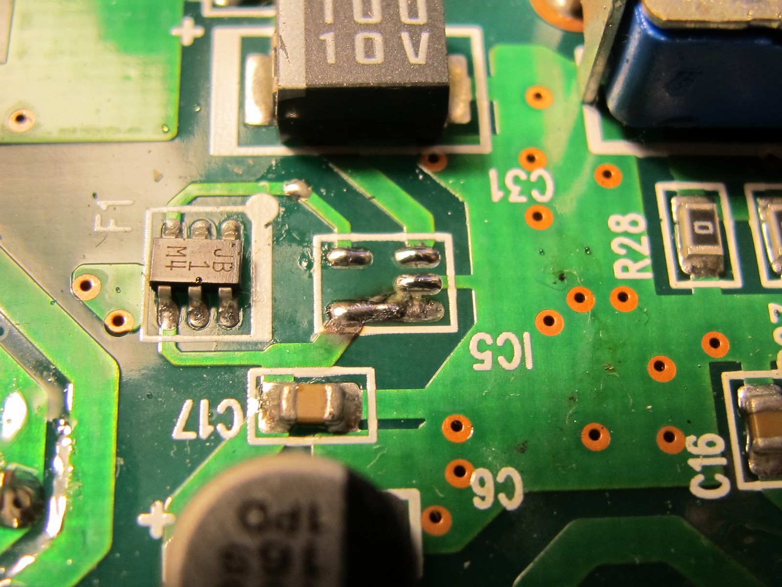
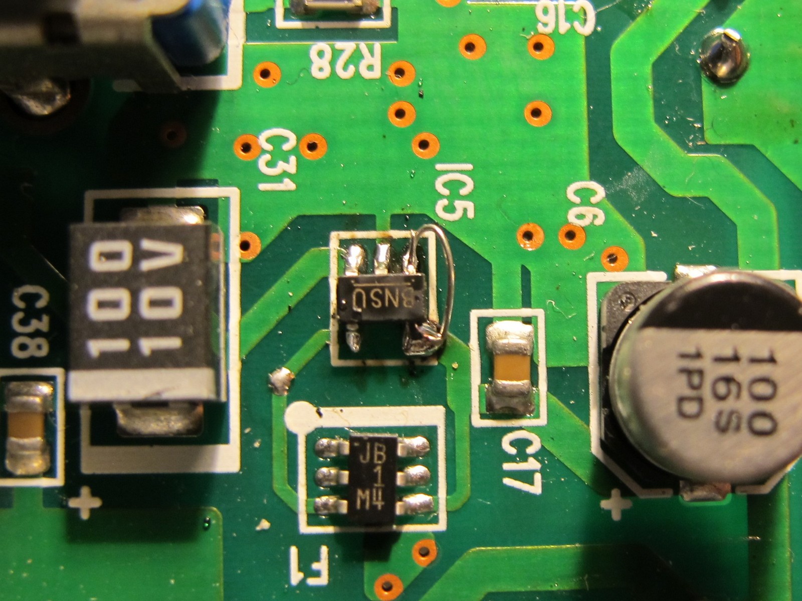
It was time to read the manual of the burned IC. Pin No. 1 was missing – not bad, it was just shutdown pin (probably low current). But still it was missing.
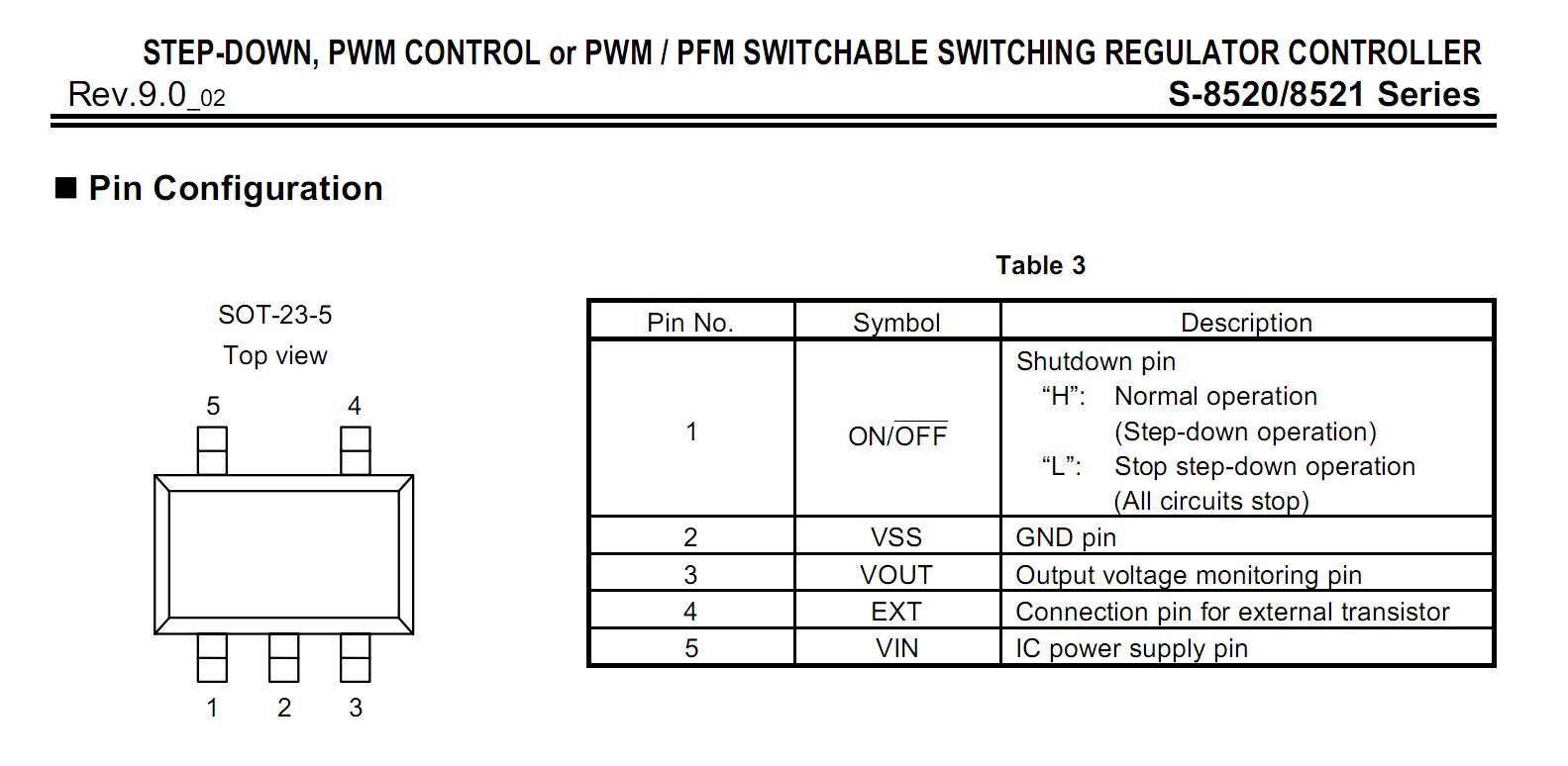
The Korg Microkorg service manual schematic stated clearly: for IC5, pin 1 was connected with pin 5 (normal operation mode). This was a good information, as pins could be connected externally with thin wire. On the left side of the schematic, you can see FU1 fuse which should also be replaced. There was also a chance, 6,3 V rated capacitors failed, but I didn’t worried about it now. Besides they looked good – not swollen or cracked on top. A lot of things could happen when power supply specs were mismatched so much.

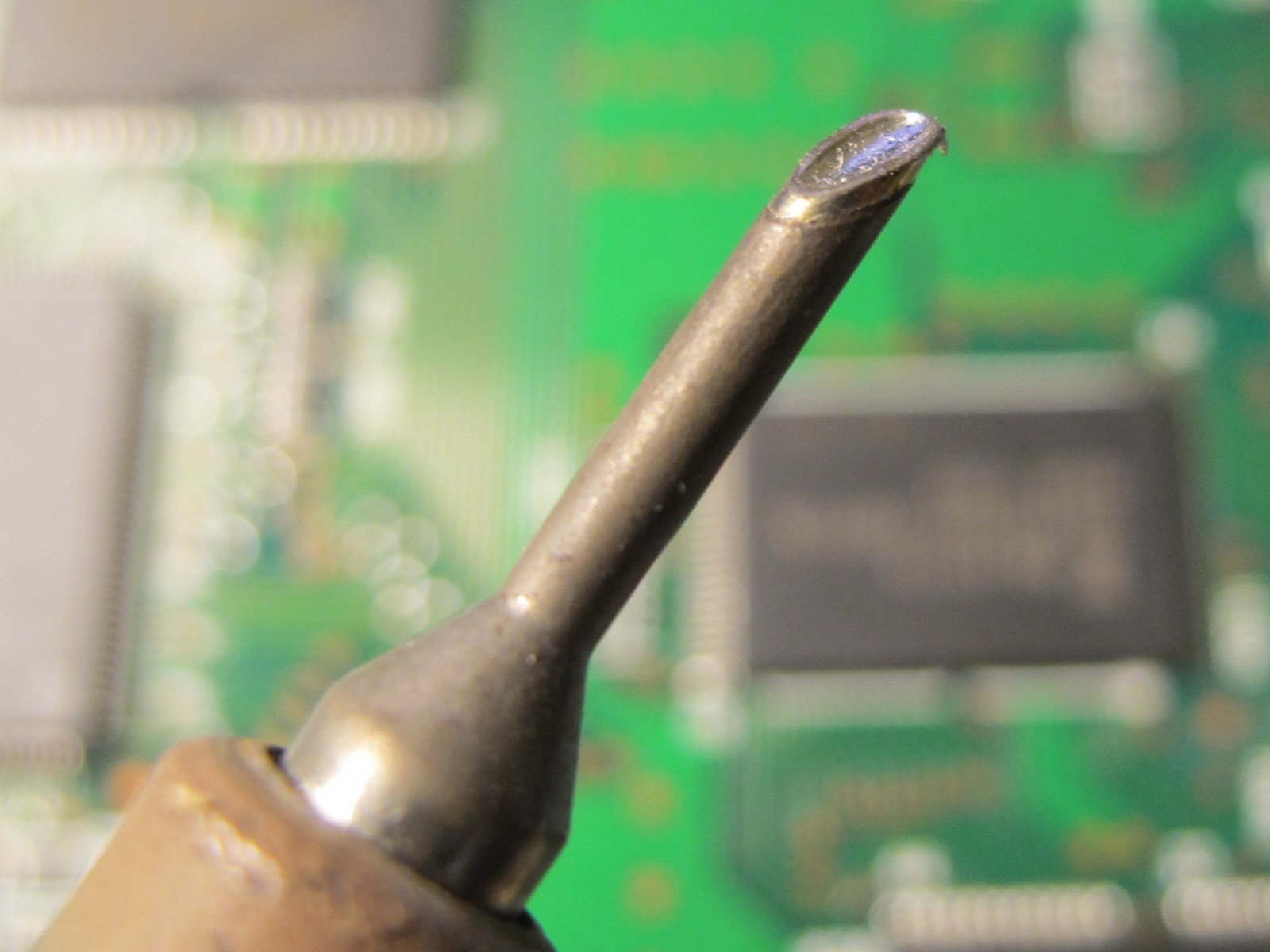
Next, I’ve cleaned pads from remaining solder using miniwave soldering tip. It is very handy not also for SMD soldering, but also for removal of excessive solder amount. For my Xytronic soldering station it was guite cheap, around 6-7$ few years back.
After so much preparation, soldering new IC was just a pleasure – pads were clean and I had to solder only 4 pins 🙂 As pin 1 was not connected to the PCB, I made an ugly external bypass to pin 5.
The FU1 removal and soldering was easy and not very spectacular, so I will just leave it to your imagination.
The result
I fired up the unit. Display stayed off and only 2 green signal LEDs flashed, as before. The voltage on FU1 fuse was exatly 3,3 V, as it should have been. So, the operation was succesfull, but the patient was totally dead before I’ve even started. Probably DSP not survived the power supply overvoltage, which in case IC5 stopped to control U1 properly went to over 20 V p-p.
And that’s the sad end of my Microkorgs story. Hope it is now somewhere in Korgs heaven and plays “On the run” sequence.
Good bye
Jack
Always look on the bright side of life. Now you have bunch of fine parts, to build something you do not buy at the store. In any case, you are building excellent things. Trzymaj się dobrze ze swoją dziewczyną!!
Thanks! I’ve already forgiven her 🙂
at least it wasn’t a Jupiter 6
For korg micro owners in regards to overvoltages due to wrong power adaptors or shorts here’s my updated engineering fix at inside end of 9vdc power plug on main board install power limiting diode it’s ordinary black diode with limiting nothing over 9 vdc 1000ma to protect your main board in future from smoking parts up vs a fuse fast blow job also can work too just a thought it’s cheaper than sending it out in mail and praying it’s fixed by exspensive repair and for how long will it work .
Been here before. This usually destroys the surface mounted main processor chip. If this is destroyed, who knows how much further the damage has gone. The traces on the main board are pretty easy to lift and damage if repair is attempted and should be left to professionals. The dire straits of newer products and mass production.
The same happens with Korg Triton Le and some other Korg models. I’ve repaired some boards and the DSP always survived. The RAM chips are the ones who failed. After the repair, I installed some zener diodes for protection before and after the 3,3v circuitry.
Thanks! It is good to know. Cheers!
I’m a wee bit late down the road here but, you wouldn’t happen to still she keybed for this would you? I just picked up a Microkorg with a bunch of missing keys and I’m planning to not just repair it but also upgrade much of the external parts to aluminium
The problem isn’t at dsp, the short circuit pierced cpu – HD6412320VF25
cpu is responsible for turning on the synthesizer…
If the problem was in dsp, then the microkorg would turn on, but with distorted sound and an inoperative logical system of buttons and knobs…
Thanks for this post! I have a microkorg that has an issue I have not been able to diagnose…niether the pitchbend or modulation wheel OR any of the 5 edit knobs are working. I checked the ribbon cable from the mod and pitch control and it is properly seated. Since none of these controls are working I doubt that it is the controls themselves…I’m hoping it’s not a CPU issue….everything else on the synth works properly. Any thoughts or suggestions for how/where to get this machine back in action is greatly appreciated!
I have the same problem. I bought the microkorg with that problem. I haven’t been able to figure out where the error is coming from. I think the fault may be in IC18.
I have verified that the resistance is modified when we rotate the knob, for example, 1, the value changes on pin 108 of IC 18. Consequently I think that the problem may be inside the IC. The same goes for the mod wheels, and knobs 2,3,4,5.
I believe the previous owner may have plugged in an adapter with reverse polarity or overvoltage The motherboard has obvious signs of being serviced
I’m thinking of replacing IC 18. Otherwise the synth works. sound good and I can edit the programs from the PC, but I can’t save them because it’s impossible to change the write protection.
How did the problem arise for you?
If my message is not well understood, please let me know. any help will be welcome
Best regards
I have the same problem too. I bought the microkorg second hand to fix it. After repairing the power supply circuit, the microkor starts up, it has a good sound but the potentiometers do not work. Then I realized that the analog inputs of the CPU are not working (or at least not responding). It may be that the VREF input is burned and that is why it does not work.
I have also done the diagnostic tests that appear in the service manual and I have been notified of an error when I do the wheel calibration and also when I tell it to show the ROM version number.
I would love to know if you changed the CPU and I hope that worked in your synth. It seems that the transplant is not going to be very easy.
have a microkorg that is missing page Edit Select 2 Midi. I replace knob but that didnt work. can you help
Women ☕
Hi,
I have a problem with uncalibrated edit controls (potentiometers for changing the parameters values). Pot “3/EG ATTACK” changes a value from 0 to 119, while pot “4/EG RELEASE” from 9 to 127. I wonder if someone knows, are they somehow calibrated (nothing about that in the service manual), or shall I check the combo diodes WD4 and WD5 for a leakage?