As far as I remember, Glidophone was one of my first synth projects (May 2012), somewhere around Stylophone clone and Atari Punk Console. And as some of my early synths, it failed to generate any sound. I tried to resurrect it around 2016, but I was unable to find an error. Finally it ended in my “drawer of shame” (between countless 808 clones). I decided to give it a third chance after I found shamed pieces of my Glidophone durning the 2018 Christmas cleanings.
Surprisingly the errors were quite easy to track. I used 500kΩ potentiometer instead of 2,2kΩ which caused vibrato generator to operate at very low, almost unnoticable frequency. Also the circuit was missing an output capacitor to remove constant voltage. As I finished repair, I though I can do better and make this oldschool DIY project shine.
So, let’s forget about my failure and concentrate on new, updated, better design. First, a bit of introduction to this beautiful project.
A little bit of history
Glidophone DIY synthesizer project was introduced in March 1968 (over 50 years ago!) by Electronics Illustrated. In 3-page-long article Fred B. Maynard explained principles of the electronic design along with schematic, PCB design and a list possible modifications (which is a very nice touch).
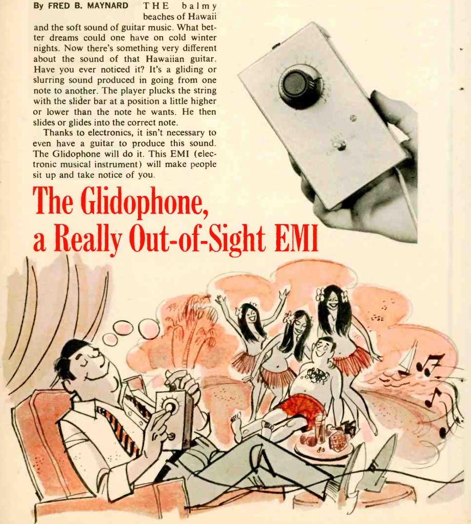
This synthesizer was designed to sound like Hawaiian guitar. But don’t let the girls on the drawing above fool you! Once you run the Glidophone your girlfriend and cats, especially cats, will hate you! Nevertheless, it is a clever circuit getting most of only 4 transistors – for such a simple device it has quite a lot of sound shaping possibilites.
My modifications of the original design
I slightly modified the original circuit, so schematic presented below is not exactly identical with the one from 1968. The basic version of Glidephone had only two controls (PITCH potentiometer and PLAY switch), but as I mentioned manual describes some additional mods for envelope decay time and vibrato circuit – in my build I’ve included all of them. I will not present the 1968 schematic, as it is very hard to read. In case one day you want to compare my reworked design with original (link), here’s a list of mods:
- DECAY TIME depended on constant 220kΩ resistor (R16 on original schematic) which was replaced by serial connection of 470kΩ linear potentiometer with additional 4,7kΩ resistor (so resultant resistance can’t reach zero),
- 220kΩ (R4 on original schematic) resistor was replaced by 470kΩ linear potentiometer, so VIBRATO DEPTH could be changed fluently,
- 1,8kΩ resistor (R6 on original schematic) controlling VIBRATO SPEED was changed to 4,7kΩ linear potentiometer (if resistace reaches 0Ω, generator just stops),
- output capactor (47 nF) was added to remove constant component (C7 on reworked schematic below),
- R3 resistor value (original and reworked schematic) was changed from 1,5kΩ to 1,2kΩ due to part basket optimization,
- output amplifier stage along with speaker was added to keep device self-contained and fully portable,
- power supply LED and reverse battery polarity protection diode was included.
In case you want just an simple standard output jack socket, just wire it after VOLUME potentiometer and leave the whole output amplifier circuit.
How it works?
Transistor T1 and T2 forms a tone oscillator (VCO), which is resistance tuned (via PH potentiometer) and can be frequency modulated. The modulating “sine” shaped signal is created by RC Twin-T oscillator (LFO) build around T3. This signal is fed into T2 transistor base and causes T1/T2 oscillator frequency to vary. Audio signal from main oscillator goes to a simple voltage controlled GATE designed around T4 (which acts as a very crude VCA).
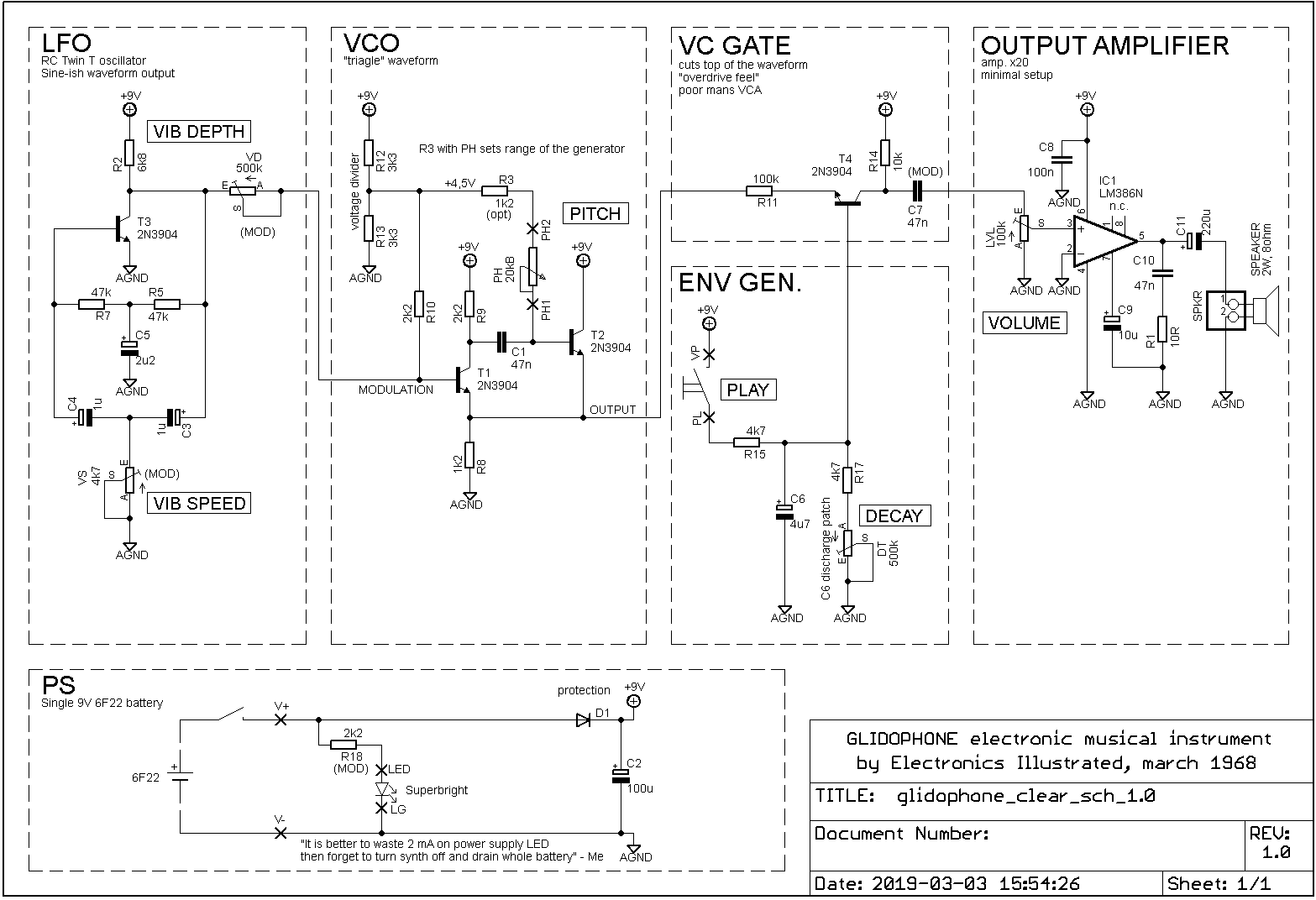
C6 storage capacitor along with R17 discharge resistor connected to T4 base works as simple envelope generator, where R17 with DT potentiometer controls DECAY TIME (original manual calls it sustain time). When PLAY swith is closed, C6 charges rapidly, opens the gate and lets audio signal go through. When PLAY switch is opened, the charge stored in C6 tends to hold the gate open, but the charge leaks via R17/DT causing the gate to close gradually – sound gets less intense and the harmonic content of the sound changes as the gate clips the signal. Check the waveforms below:
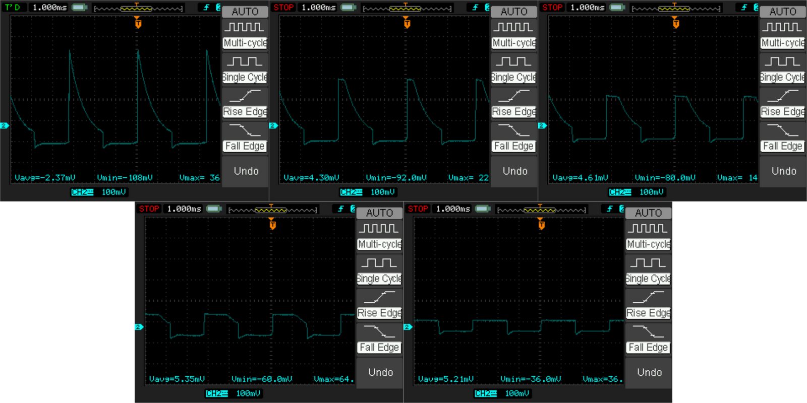
As you can see, VC gate just clips the input signal and the output waveform shape is changed from saw- to more square-like. Additional C7 capacitor filters the waveform a bit and a result sounds like this (notice, how the sound gets brighter as the decay progresses; vibrato turned off to make the clipping effect more noticable):
This (planned or not) feature makes the sound device produces really interesting and unparalled. It seems like it wants to scream while going silent, like absolute opposite of Buchla LPG. I don’t thing I’ve ever saw a similar solution in any (non eurorack) sound synthesizer.
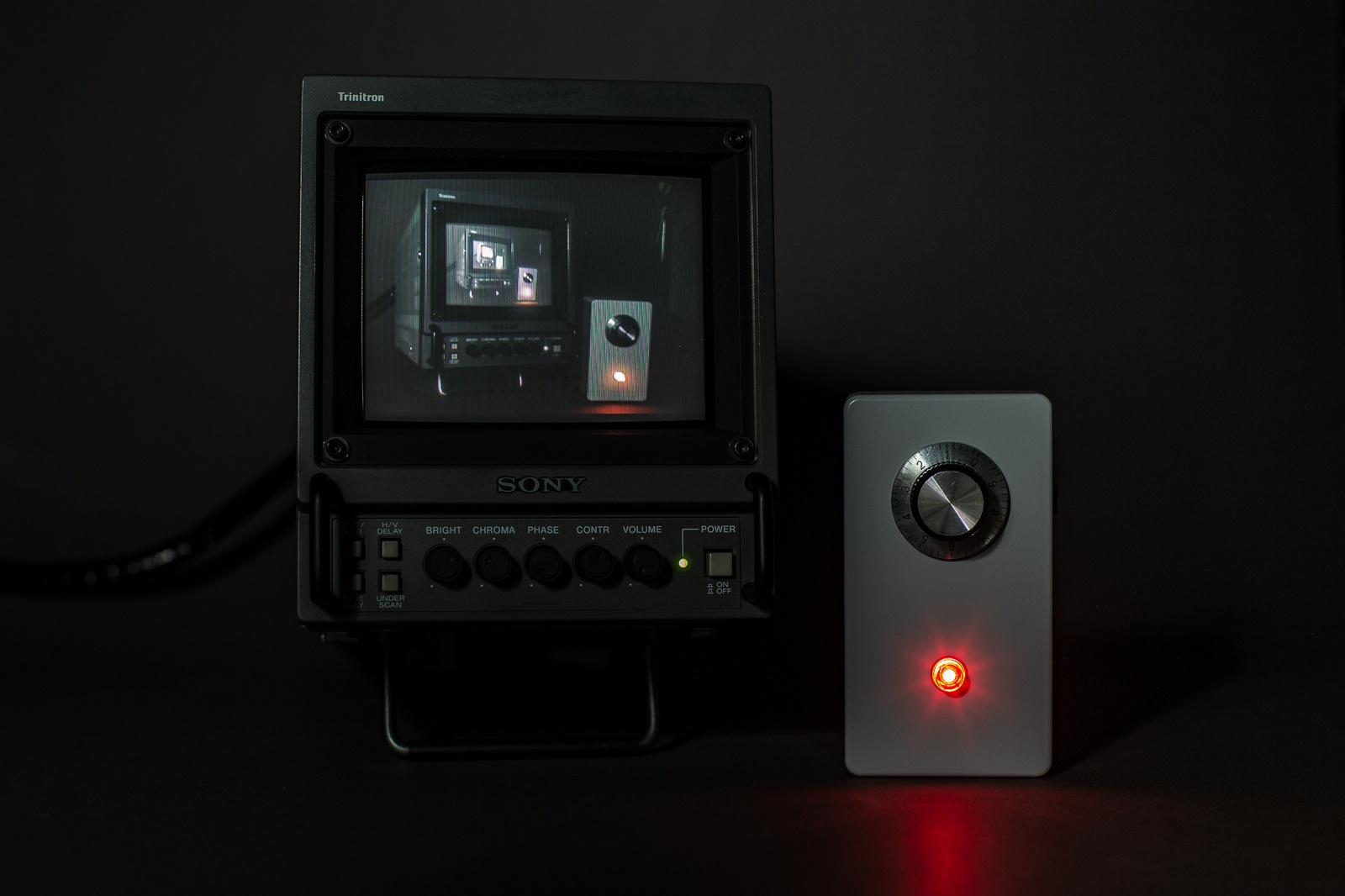
External design
I tried to keep the synth in cheap-retro-sci-fi-style. Something like nuclear doom device remote control or radio tracking device from cheap ’60s movie. I hope you know what I mean. I wanted it to be simple, with big knob and angry red light, without any unnecessary stuff like controls description… and visible on/off switch. On the other way I hoped to avoid an “unfinished” look of a guitar effect without knob captions. In fact, the enclosure design presented in Electronic Illustrated was so raw and brutal, I didn’t have a lot to do.
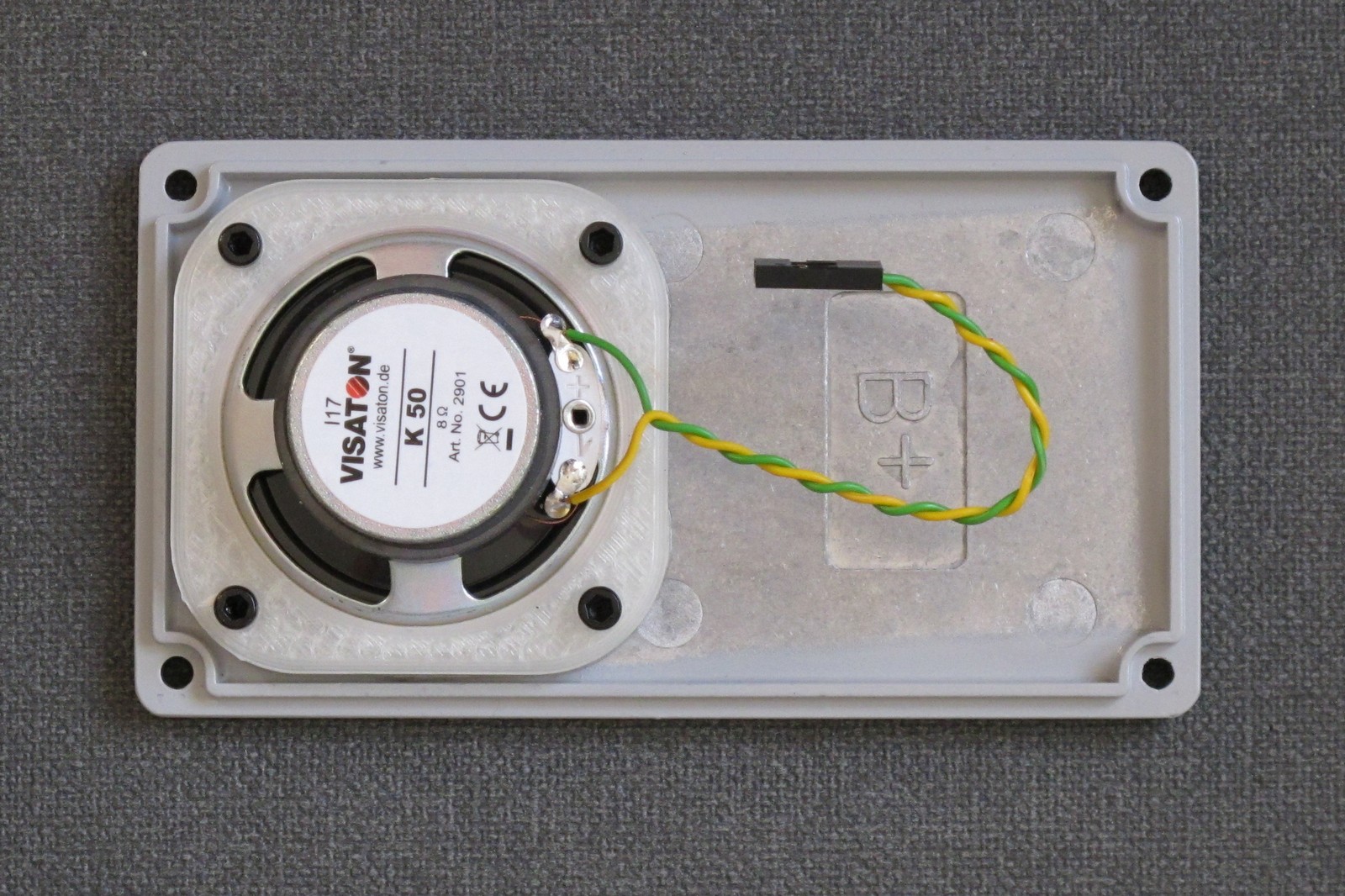
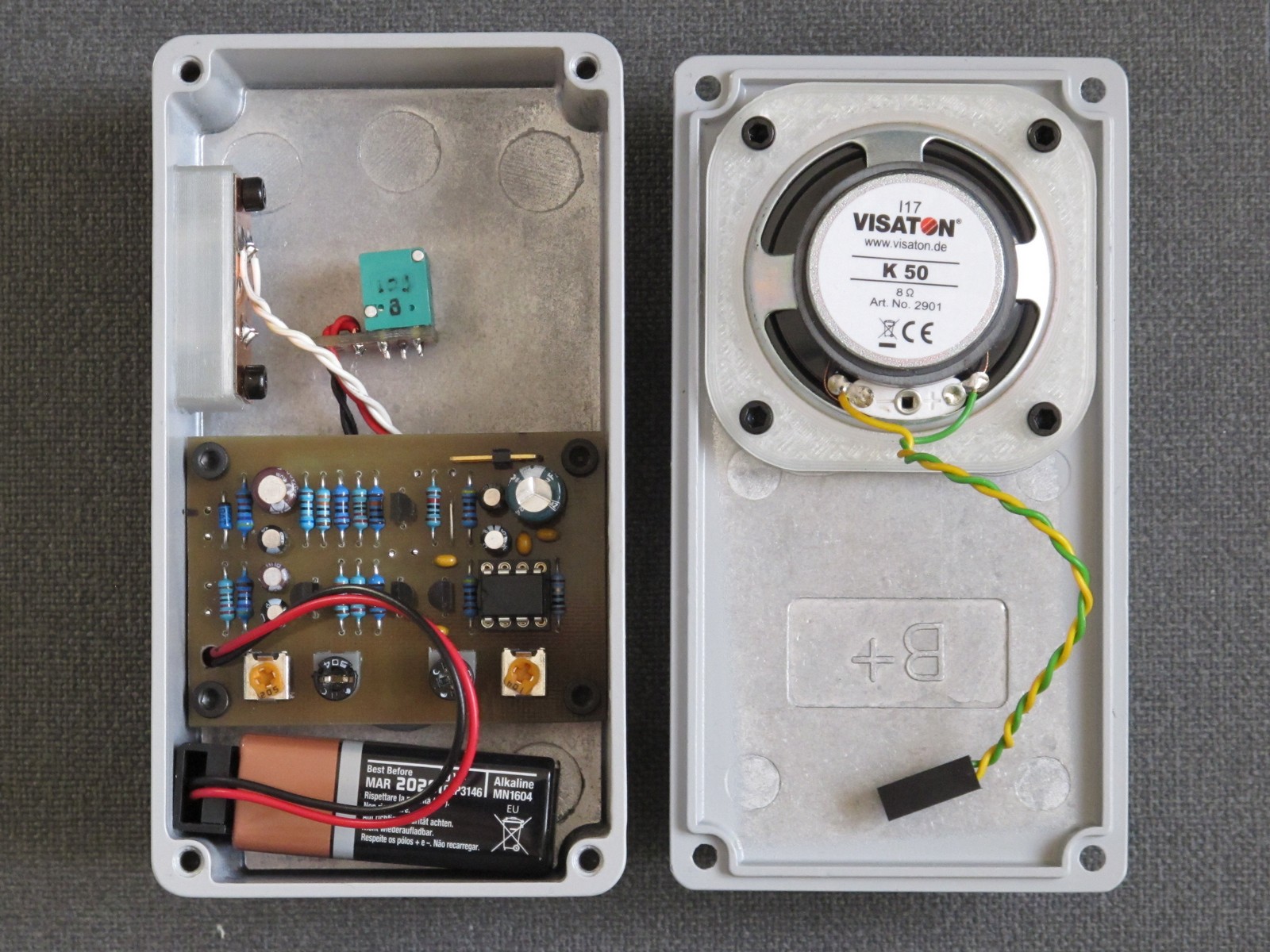
You may not believe it, but I really made a vector design first! I decided to use silver or light grey enclosure, finally I ended with “(Hammond) 125B style” from Tayda for 6$. I also wanted the box to be large enough to fit Visaton K50, the cheapest 50 mm above hopeless quality speaker I could find (~3$).
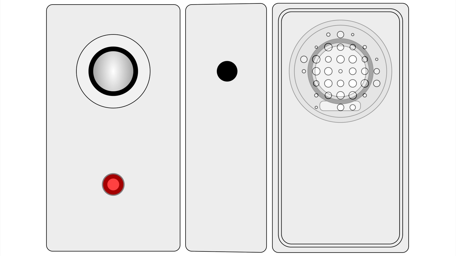
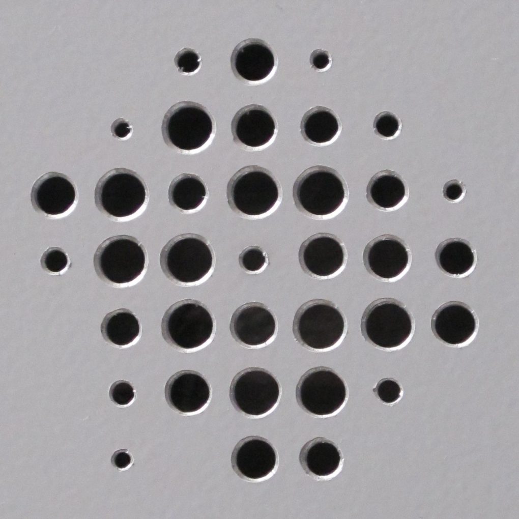
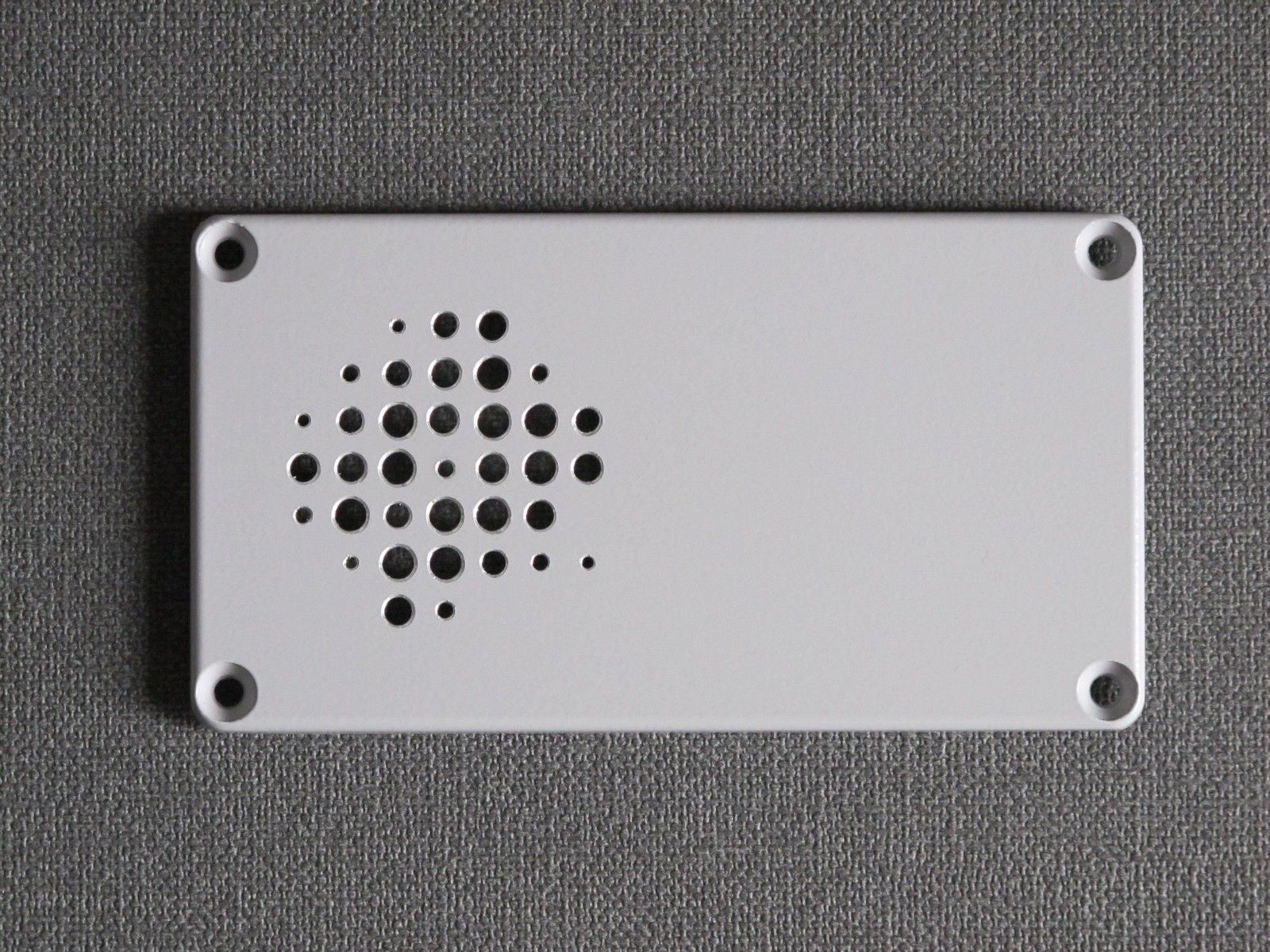
I had a problem with speaker hole: I didn’t want to use big round opening with tin mesh cover (or something similar), as it would be too complex to make and probably look more ugly then I imagined. Finally I designed a pattern, inspired a bit by old radios, which to some level is resistant to drilling errors. The holes are placed on a grid, but their size differs – this way a small displacements out of the grid are virtually unnoticable. The use of grid allows also for easy use of compound table while drilling.
After I got the enclosure, I moved to matching the rest of the visible components – knob, light cover and switch button:
- transparent red light top cover used as power on indicator comes from vintage telephone light bulb holder manufactured in Poland; it needed some love to be used with LED, but I personally think it is the best looking small light source cover ever; found in garbage,
- big, 37 mm partially aluminum covered knob in “serious measurement equipment” style for PITCH control, bought in Tayda,
- side PLAY button – black 9,5 mm Omron B32-1610, a match for Omron B3F-4050, a switch with low operating force of 1,27 N (and believe, me you can really feel the incredible fluffiness of pushness it delievers),
- on/off switch – integrated in PITCH control.
And where are the vibrato and decay controls you may ask? Carefully hidden inside.
Internal design
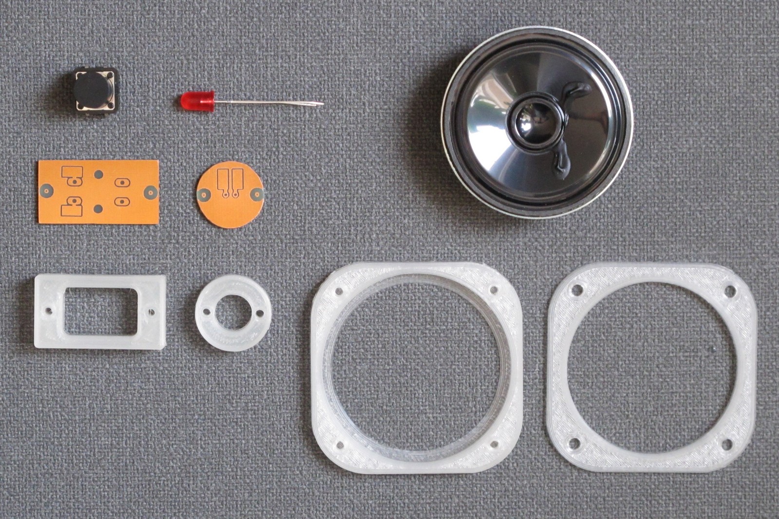
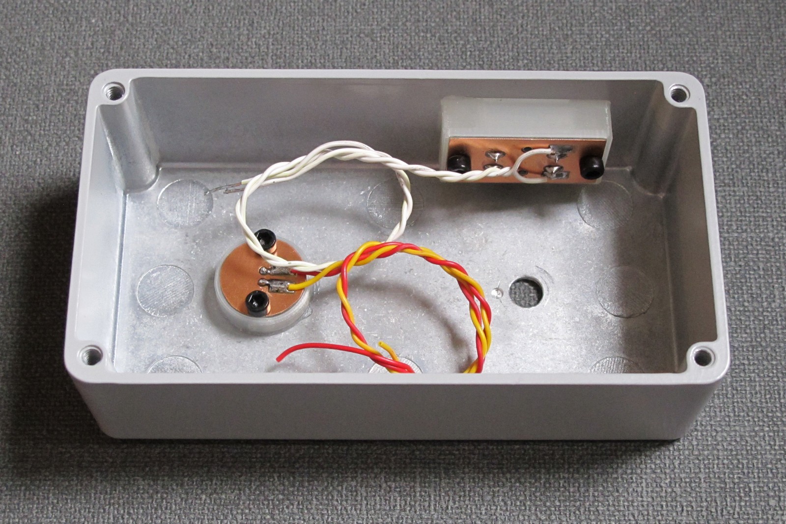
After critical external components choice and placement there was time to design the internals. I wanted enclosure to be as screw-free as possible and decided to use a group of 3D printed holders (presented below):
- round LED PCB holder (top left) – positions LED on the correct depth related to red bulb enclosure, so the light is evenly diffused (I carried few tests to be shure it is perfect),
- rectangular PLAY PCB switch holder (top right) – a lot of force may be applied here, so I made a contact area with aluminum enclosure quite big,
- speaker holder and cover (bottom) – Visaton speaker didn’t have and mounting holes and it had to be attached somehow.
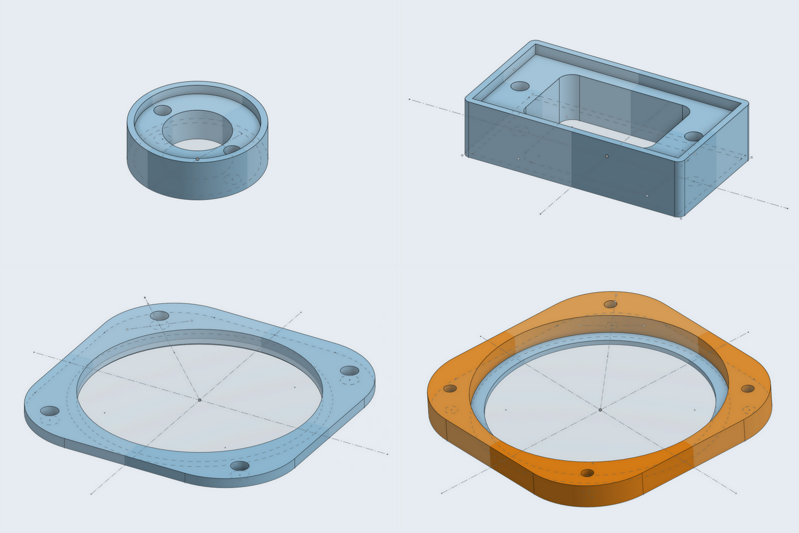
My first idea was to use brass threaded inserts in the bottom part of speaker holder (orange part), but later I decided to just screw the screw directly in the print (it was not my brightest idea unfortunately). Parts were designed to be fast to print and not overcomplicated (after all, no one will see them). The project was made in OnShape, free online 3D tool (it works really great on my almost 10 years old PC!). All parts were later printed with hard tuned Prusa clone and tranparent Verbatim filament.
PCB design
3 PCBs in total may seem a bit like overkill and probably it is. One for main synth circuitry, one for LED and one for switch. The main PCB holds synth engine with its controls and amplifying stage. The “hidden” controls are related to less often used functions, like:
- volume (LVL),
- vibrato speed (VS) and depth (VD),
- envelope decay (DT – I have no idea where this abbrevation came from).
As the only component located on the enclosure cover is the speaker, its wires are connected to PCB via 2 pin header (SPKR). As I etch boards myself, I often use a small trick to make future drilling easier: the mounting holes have vias placed inside to make a good start for drill. This way 3 mm holes are exactly where they should be.
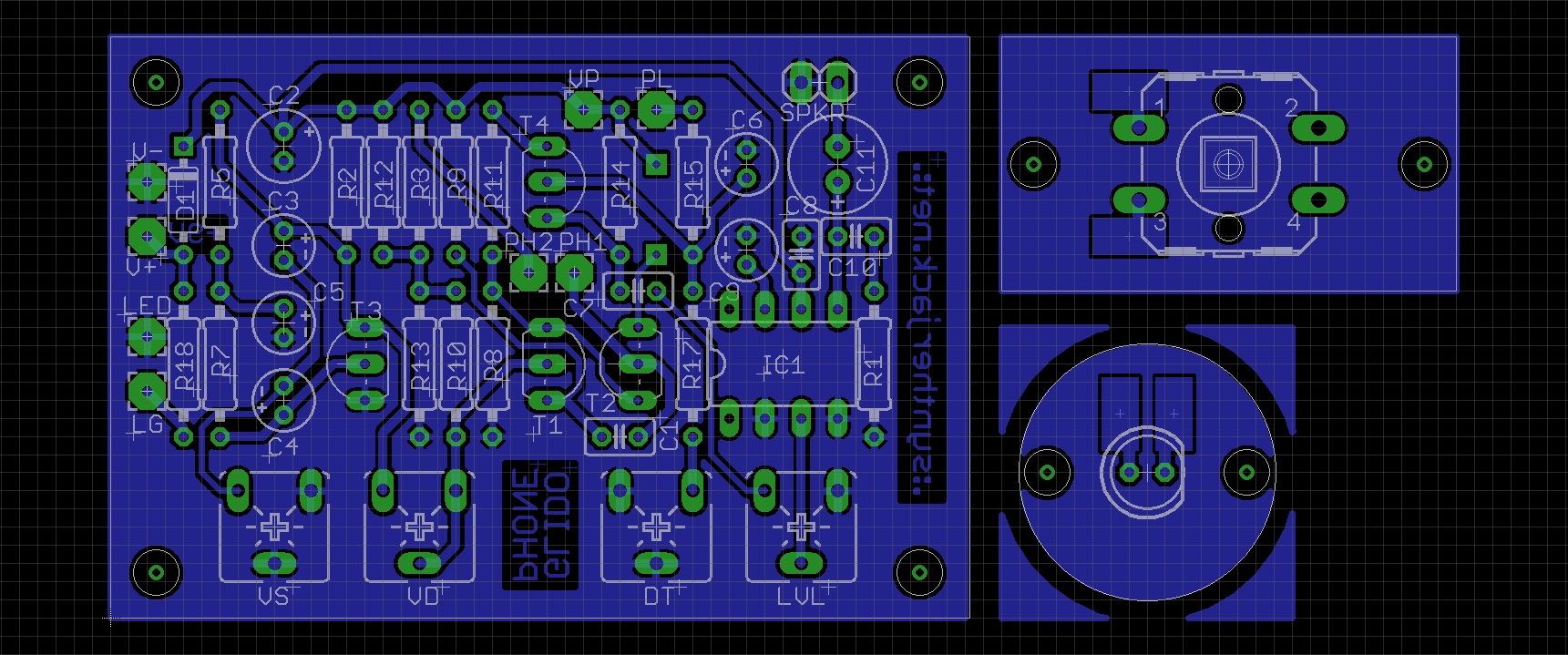
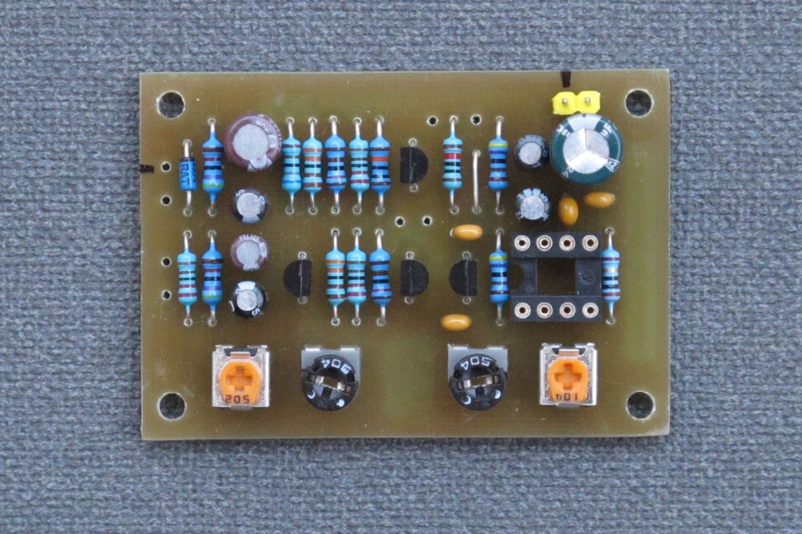
All used components are through hole type. “Brain” PCB is one-sided and measures 60×40 mm. 4 screws are needed to hold it on place, as some force may be applied to trimmers. Actually there is one more small PCB for potentiometer, you can see it soldered in later section.
Etching, glueing and screwing everything together!
I spent some time on planning in which order assembly all the parts, as it was not so obvious as one may thought. F. e. switch holder must be glued with PCB attached, to position switch cap properly. Also it would be inconvenient to screw PCB to the glued 3D print due to lack of space. The same thing applied to LED holder.
So, the first thing – the PCBs. They were made with photo UV method using Bungard board with photoactive copper plating, then etched, drilled, populated and soldered. The size of the board matches the enclosure – there was no need to make it smaller and use SMD components.
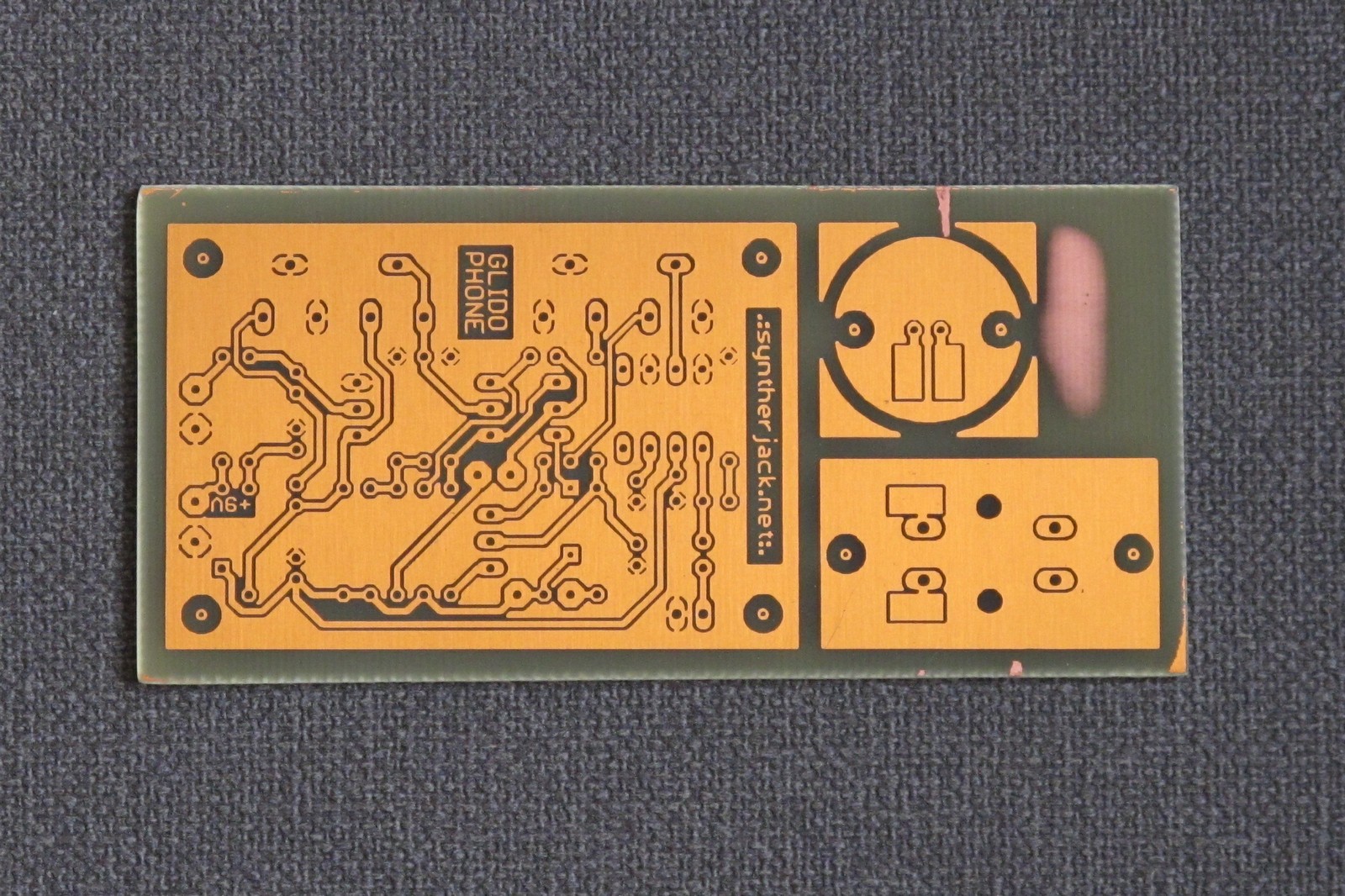
You may notice a brighter, ginger spots – it is unprotected and not full etched copper. I would dissapear after few more minutes in etchant, but all the traces will also became thinner (as they are not protected from sides). There was no need to wait as those parts of PCB go to trash anyway. It this case it wasn’t so important, but may be a problem with a large PCBs with a lot ot thin traces combined with significant areas without copper (made f.e. as 230 VAC isolation).
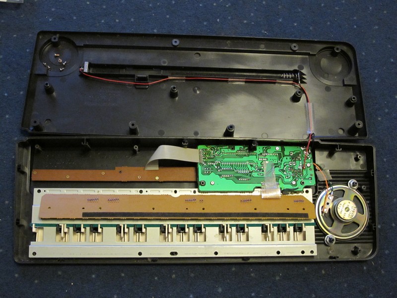
The small PCBs were cut with sheet metal sheers, then grinded with Proxxon rotary tool equipped with abrasive head, finally finished with fine file. Drilling them and soldering wasn’t a grueling job. Now, as I look at this photos I think, it definitely was an overkill. 2/3 of those elements are redundant. But how fun it was to design them! (In fact, a lot of low cost range synth use similar holders integrated into enclosure, like this vintage Yamaha PSS-50 – speaker without mounting holes has to be attached somehow).
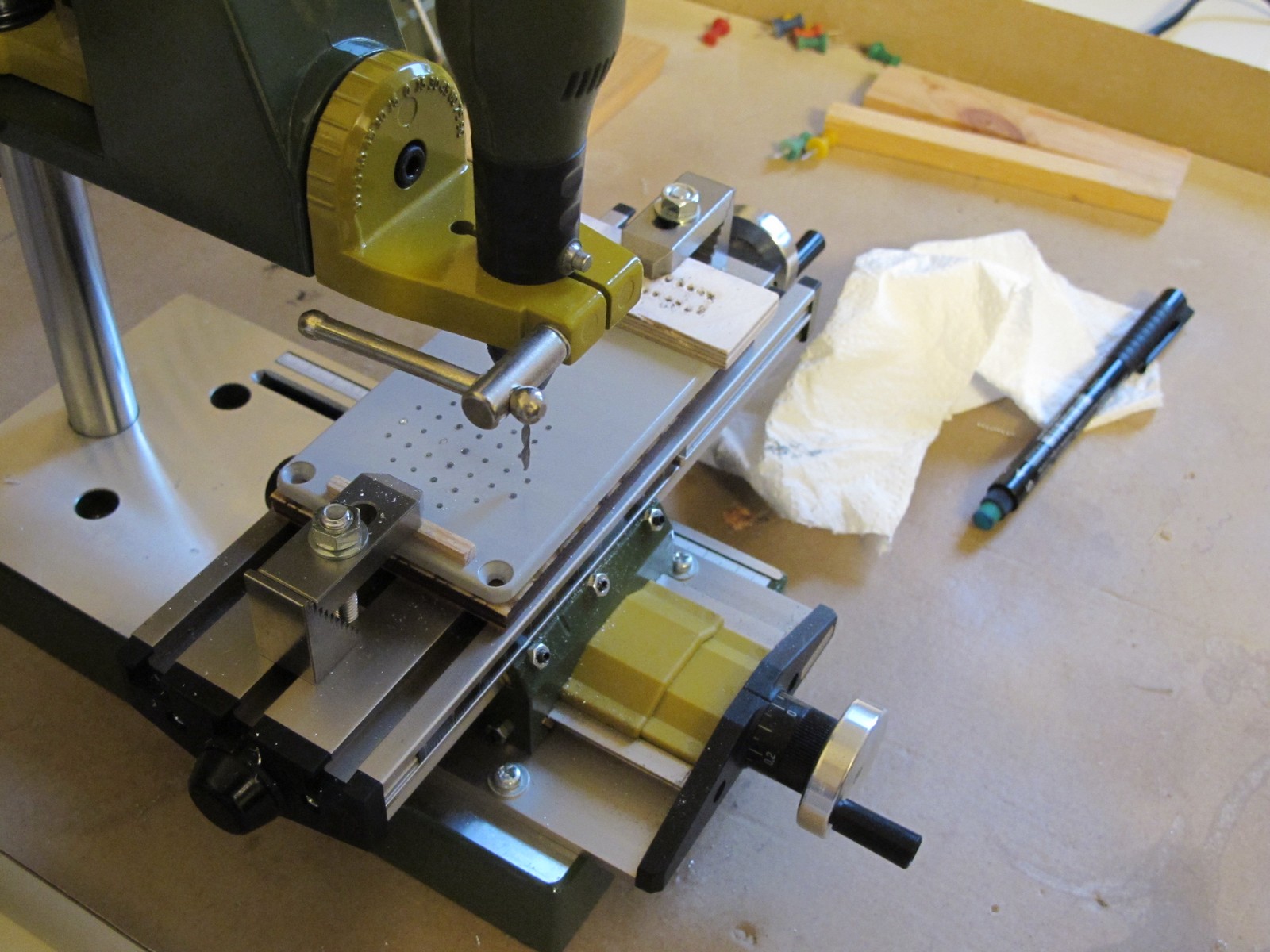
After I finished main PCB, it was time to start working on enclosure. Just few holes to drill. As the pattern on the speaker hole was complex, I thought it will be a good idea to drill small 2 mm holes first. I used my old trusted Proxxon Micromot 50/E along with MB140/S drill stand and KT70 compound table. As the holes were designed in 6 x 6 mm grid, it was easy to set drill in the correct position with handwheels.
Then, the small holes were reamed to the target diameter, as in created project, with larger drills and finished with hand deburring tool to get rid of sharp or uneven edges. The final result was much better then I expected, but if you see closely, you can spot some errors. The reason was, one small area in alloy box cover was rock hard and the drill started to slide sideways when I applied some force (third row from top, fourth hole from left). I fixed it with file, but still it is not aligned to other holes.
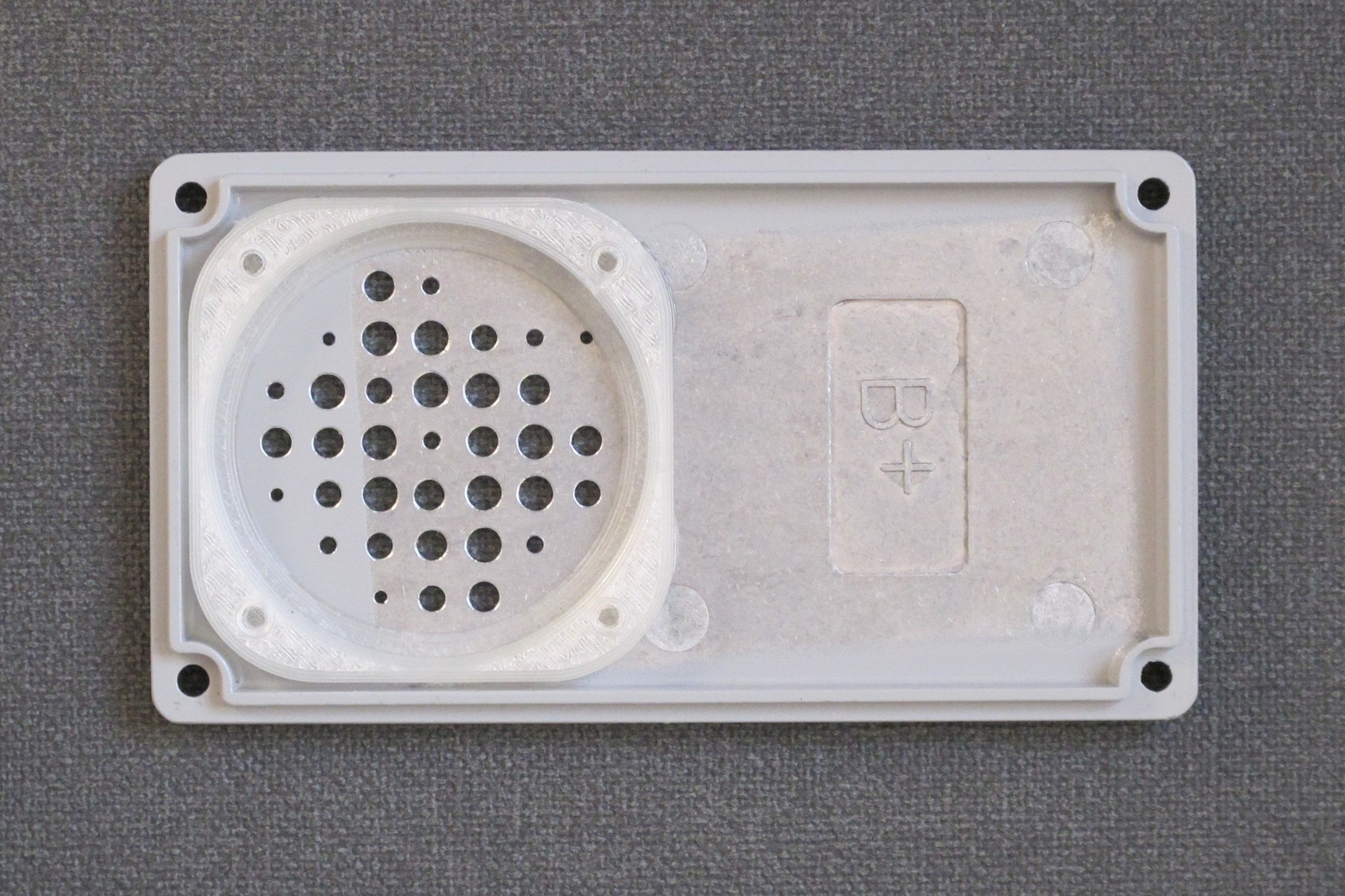
Now, the speaker holder! Thanks to careful measurements it fits like a glove. (To be honest, it is a second holder design; first was too large.) The alloy was degreased with isopropyl alcohol, then 3D print glued with transparent epoxy adhesive. It was the time I thought: “How will 3D print behave if I just screw the screw directly in it?”
The answer was: “Fine, if you will do it once”. After third time I rescrew the 3D printed parts together, one of the forcefully threaded holes just couldn’t take it anymore and broke. I had to wrap the screw in paper to fit it again securely. Anyway, it looks quite pro for home build. I just love the look of cheese head hex M3 screw in the morning.
Because of the difficult future access to the side mounted enlosure components (LED and switch), the remaining PCB and 3D printed parts were first soldered (with wires), then screwed and finally glued. This way I could be 100% shure all externally visible parts were centered. This was very important, as the switch cap had only around 0,5 mm clearance and I didn’t want it to rub the enclosure.
On the picture above you can notice an already drilled potentiometer hole with another, smaller blind hole next to it, serving anti-rotation purpose (small inset next to pots shaft goes here). To make it, I’ve just drilled a 7 mm hole, then put potentiometer in it and rotated few times. The anti-rotation inset made a visible circle around it. Them I punched a guide hole for 2,5 mm drill taking care not to go through (in fact, even if I bored through, the hole would be covered by the potentiometers knob).
You may not see it from the top, but there were few tricky moments in the design. It looks like there is a plenty od room inside the box, but in fact there isn’t. After you close the enclosure:
- there is below 1 mm space between speaker holder and switch holder,
- speakers magnet is very close to potentiometer, around 2 mm,
- voice PCB almost touches LED PCB below it.
While designing Glidophone I missed one thing – dimensions of the speaker connector. I had to change its orientation on the PCB from vertical to horizontal, as I couldn’t close the enclosure. And the final touch: random idea driven photo session 🙂
Demo & IMHO
I tried to make it interesting so I put a bit effort to play along with Bowies Space Oddity. I know originally the song used stylophone, but Glidophone also fits. Do not judge my musical skills. I really wanted to hit every note. Maybe I should choose something with more intentional note slides, Walkin by Silver Apples or Good Vibrations by Beach Boys?
Instrument is very simple, but the sound it produces has its own charming (/ annoying) character. It resembles a theremin a bit, thanks to unavoidable use of slides and vibrato. You can play (or track) a melody smoothly, it’s like kazoo for electronic instruments – perfect for jamming along with friends without any musical knowledge.
Cheers
Jack
Nice work! What about to replace poor mans VCA by real LPG, of course opposite direction filter. I ´ll try it.