What a great click bait title! And in fact, true! Volca Modular specs in Korg’s manual are not exactly precise, but this is actually a good news. Let me explain: Korg made a great and much explaining manual, but (IMHO) for sake of easiness of understanding, some specs were simplified. Who wants to interact with this small gem in a more extreme way, should now its real limits. So, let’s get straight to the point.
TLDR
As I wanted to modify this thing and add some microcontroller stuff (as usual), maximum expected voltage value on each output was an very important thing to know. On the other side, maximum output voltage should be also a maximum voltage inputs can accept. Of course I don’t take any responsibility if you’ll fry your unit. Below you will find all the raw measurement results.
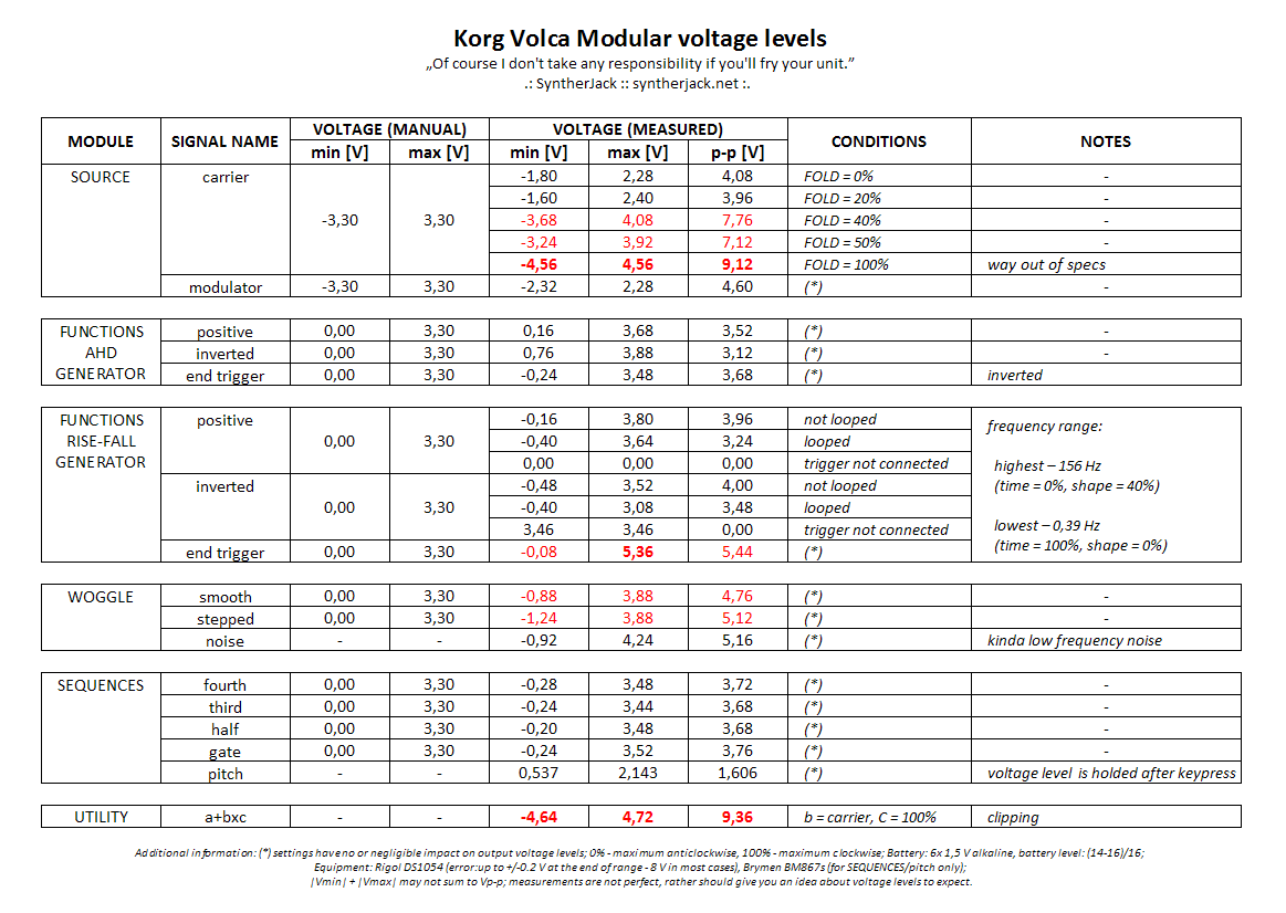
If you are interested in Volca Modular specs in more details and take a look on some beautiful waveforms, please continue. Beware! Actual values in the table may differ slightly form those from oscilloscope screenshots. You may also want to read an information how the masurements were taken.
Measurements
All the data was collected with not greatest but not bad either test equipment:
- Rigol DS1054,
- Brymen BM867s (only for SEQUENCES module, PITCH output).
The automatic voltage measurement error for Rigol oscilloscope are quite large and amounts up to +/-0.2 V at the end of range (8 V in most cases). The final table with measurement result consists of raw data Rigol outputted, but keep the errors in mind. It was confirmed with function generator and constant voltage tests.
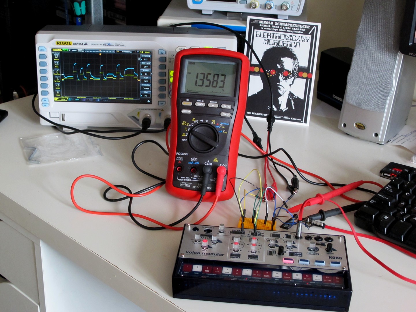
The setup was very simple – the GND from Volca Modular was gained from CV-IN, other signals straight from pin headers, then led to small testboard where they were connected with oscilloscope probes. What may sound unusual, no cats were involved (it is over 35 Celsius right now and they’re sleeping all day). All tests were performed with 6x 1,5 V alkaline batteries, Volca indicated power level between 14 and 16 dots (~85-100%).
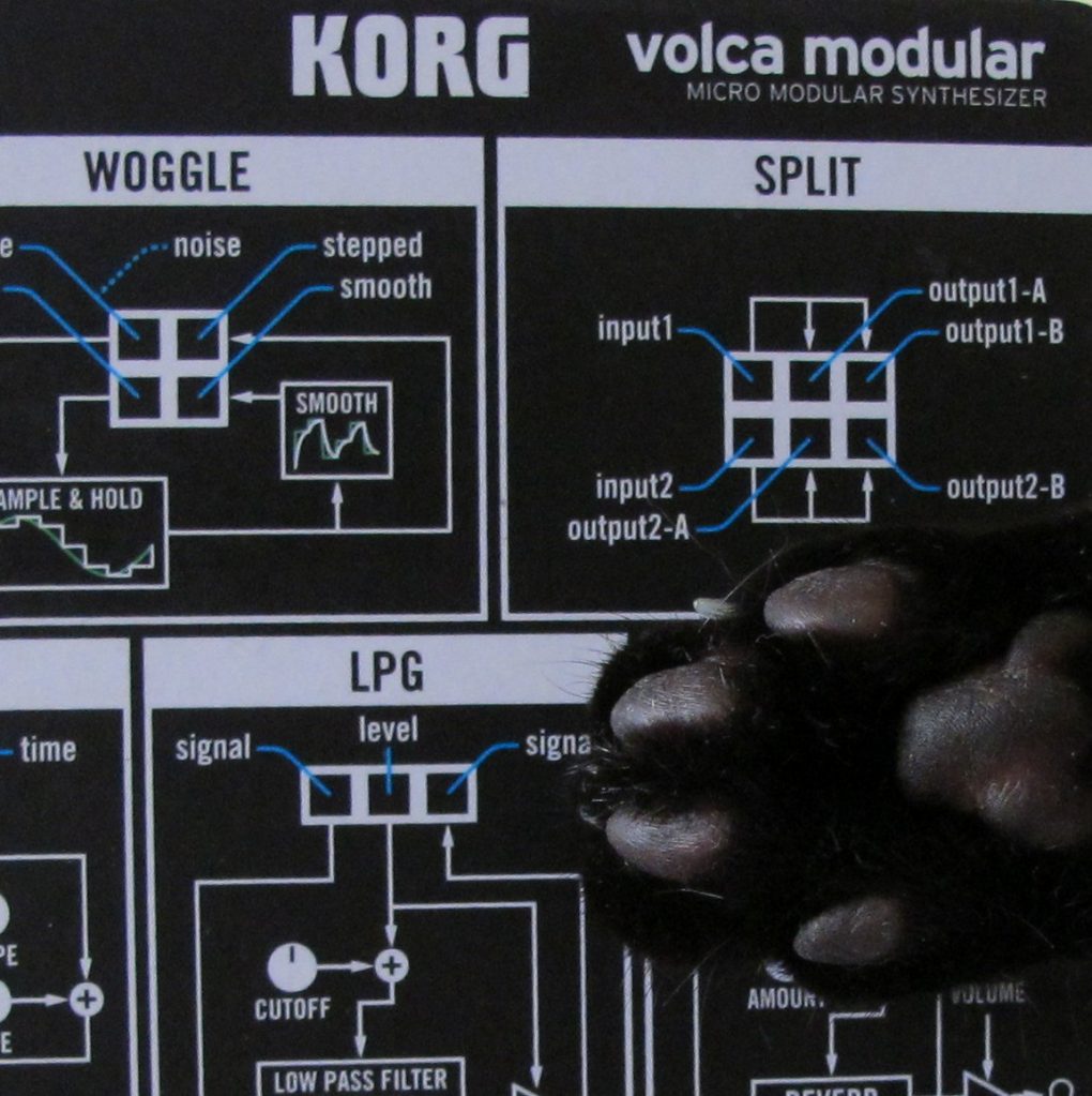
SOURCE
Lets start with the Volcas main sound source, called perversely SOURCE module. It’s a main sound source for Volca Modular and has 2 outputs:
- carrier,
- modulator.
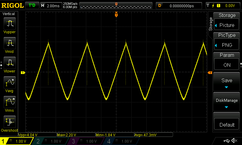
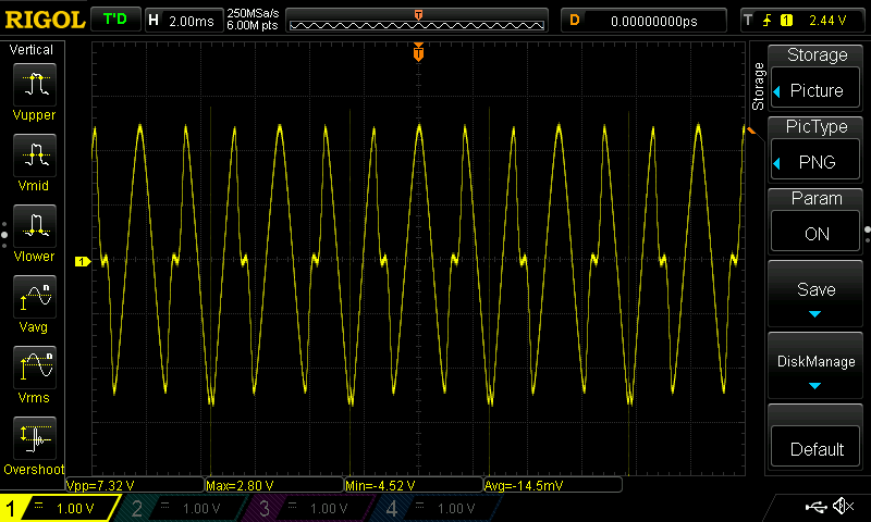
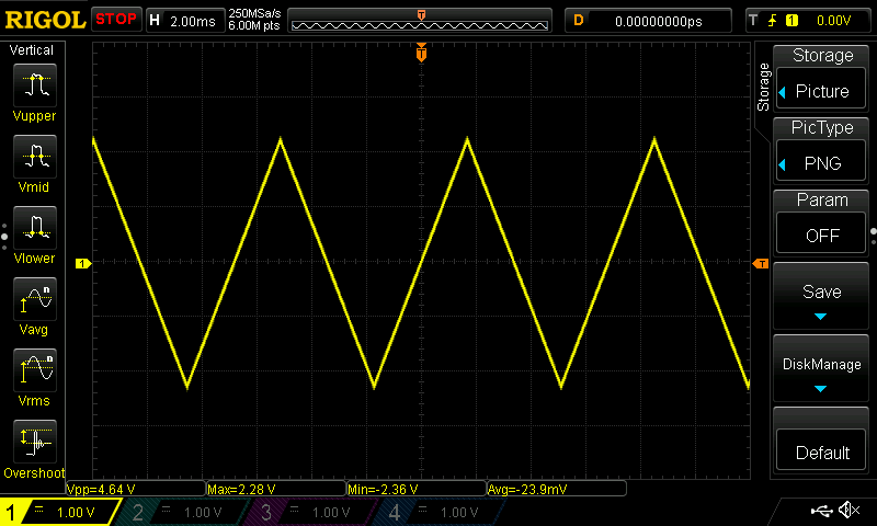
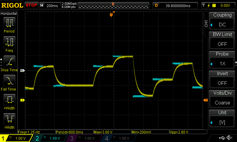
Unfolded carrier has a triangle waveshape, with a small peak and unsymmetry at the waveforms top and around 4,0 Vp-p voltage. As FOLD value is increased, the amplitude changes and has the highest value of over 9,0 Vp-p for FOLD = 100%. Check the sample waveforms below – they are quite unusual.
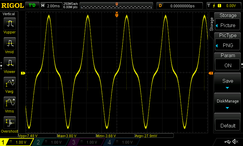
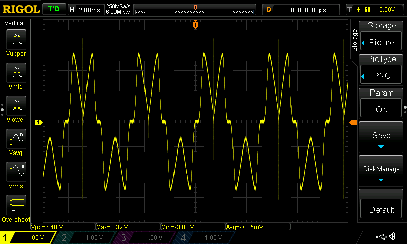

The modulator waveform is plain, good quality triangle with around 4,5 Vp-p amplitude. Very handy as a second tone source for complex Volca Modular patches. Multiplied with a carrier waveform in a UTILITY module can make an interesting ring modulation effects.
FUNCTIONS AHD GENERATOR
Its primary function of AHD (Attack Hold Decay) is to generate envelope for LPG module. Three outputs are avaliable:
- positive,
- inverted,
- end trigger.
Both envelope waveforms are rather no surprise – voltage levels are almost as specified in Korgs datasheet (0 – 3,3 V). For positive output 3,5 Vp-p with small offset were recorded, for inverted 3,1 Vp-p with around 0,7 V offset.
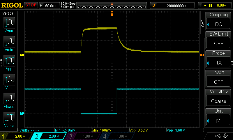

Check the end trigger! It is exactly opposite what manual states – it comes from positive to negative and reminds rather an inverted gate signal. I suppose in Volca Modular enviroment rising edge is used for internal circuitry triggering, so there is no difference if it is short positive pulse or “inverted gate”. Having this knowledge, you can f.e. use AHDs end trigger as CV source for closing the second LPGs in sync with first (of course if you don’t want to use inverted output).
FUNCTIONS RISE-FALL GENERATOR
This simple, but handy module can be used as an envelope generator or, if looped, as an LFO or audio signal source. The outputs are exactly the same as for AHD generator:
- positive,
- inverted,
- end trigger.
The voltage levels are different and depends on operating mode (looped or not). For standard, not looped Vp-p for both positive and inverted is close to 4,0 V. When looped, it drops to 3,2 V for positive and 3,4 V for inverted. End trigger output varies from around 0 to 5,4 V and is way out of specs – this is the highest positive voltage value you can get out of Volca Modular.
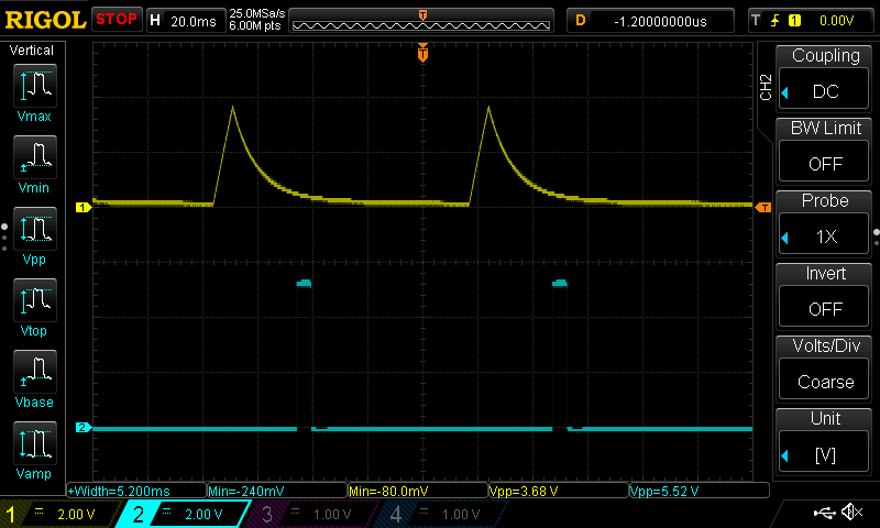
When trigger input is not connected, inverted output can act as a constant voltage source – it is sufficient to open the LPG (~3,0 V), so you can use it instead of UTILITY.
In looped mode of operation, levels are generally lower then in not looped. They are both almost in 0 – 3,3 V range and very close to statements made in manual. What is very interesting, the SHAPE control has a great impact on output signals frequency. The lowest can be obtained with SHAPE = 0% (saw) and TIME = 100% – it is as low as 0,39 Hz. The highest frequency is gained for “triangle” waveform (SHAPE = 40% and TIME=0%) – exactly 156 Hz; this way rise-fall generator can be used as crude drone audio generator. Shame it can’t go that high with saw waveform for more harmonic content :/

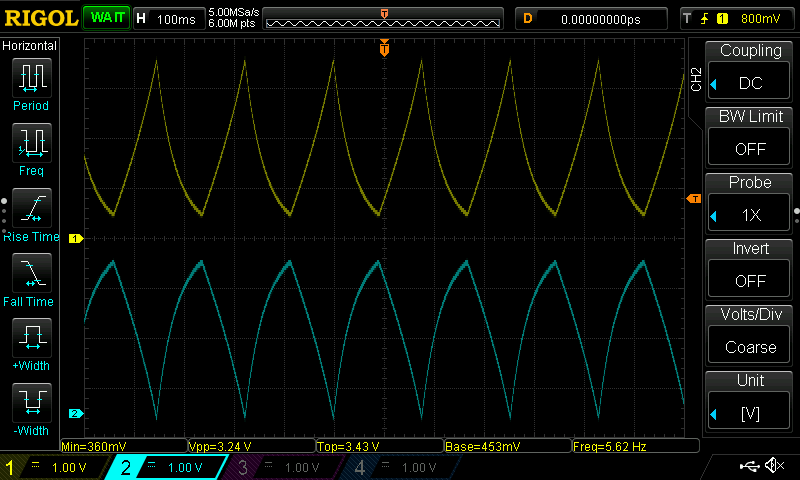

If you have looked carefully at the oscilloscope screenshots above you can notice, that waveforms for SHAPE = 0% are almost the same as for SHAPE = 100%, only flipped.
WOGGLE
Let’s move to source of random CV signals. As manual states, WOGGLE module has 2 outputs:
- stepped,
- smooth.
Both outputted waveforms occupy the range approximately between -1,0 and 3,9 V and are a bit out of specs mentioned in manual (0 – 3,3 V).
In fact, there is one more output: noise, or rather sample input, where you can try to source some kind of “noisy” waveform. It has rather lo-fi, LP filtered quality and sounds rather boring. No snares this time, sorry. But you can still mix it with audio signal in a SPLIT module to get more crunchy sound.
As you look closely at the the noise waveform, you will notice a clear pattern (repeating fragments). This may be a lead, that noise source for WOGGLE module can be digital and make use of samples. The theory may be plausible, as “classic” analog noise sources usually need quite relatively high power supply voltages.
SEQUENCE
Real king of outputs, this control module has exactly 5 of them:
- pitch,
- gate,
- /2 (divide by 2),
- /3 (divide by 3),
- /4 (divide by 4).
Pitch output is specified as 0,5 V/oct and it’s voltage levels ranges from 0,54 to 2,14 V. Can be obviously used for SOURCE module pitch control, but also works nicely with LPG level input, so higher notes can be more loud and bright (similarly to filter tracking in substractive synthesizers). Gate signal looks more like trigger and is very close to Korgs Volca Modular specs mentioned in official manual (0 – 3,3 V).
All gate / division outputs share similar specs, from around -0,2 to 3,5 V. You can use them not only to control envelopes. For instance, they are nice for creating simple percussion sounds or spicing up sequences when mixed with audio signal before entering LPG.
UTILITY
The UTILITY module has one cool feature: it can amplify signal. This way, you can check the Volcas output limits. By feeding carrier (or modulator) signal from SOURCE directly to b input and setting C = 100% you can observe waveform is clipped around +/- 4,7 V (may be slightly lower or higher, Rigol scope has quite large automatic measurement error at the end of range). Around 9,4 V is the highest Vp-p value I could get out of my unit.

You can use UTILITY as an simple overdrive – just plug your signal into b input and play with high values of C potentiometer.
Epilogue
It was quite a surprise! Volca Modular specs are not exactly what Korg have stated – analog signals can go over 9 Vp-p and triggers over 5 Vp-p. But is is not bad 🙂 It means, all inputs are able to handle those levels, at least in theory. And one more time: my measurements were made out of pure curiosity and if you want to use them in some wicked way (like applying +/- 5V LFO signal directly from eurorack system), please repeat them by yourself. I do not want to have anybody else’s machine on my conscience. But still, have fun.
Cheers
Jack
Thank you once again for another wonderfully great resource. Please is it possible to DM you thorugh email as I am in need of your expertise on a project i am working on for school
Hello, please call me, we will see if I can help 🙂
Do you think the Volca Modular could be safely manipulated using an arduino? I have really been wondering about this, and I can’t find anyone who has done it on the internet. I am keen to try, but do not want to fry the modular. If you have any insight or thoughts on this I would love to hear them.
Daniel
Hello, according to VM specs you should safely input signals from -3,3V – +3,3V range. If I am not mistaken, Arduino outputs signals from 0 – +5V range – in theory a bit too much for VM. BUT! Some outputs of VM gets very close to +5V, so also inputs should handle it. But to be safe, I advise to use Arduino outputs with some voltage dividers and stick to max. +3,3V output. Cheers, Jack
That is quite close to what I measured in terms of voltage levels. Shapes are identical. One thing is that if we mix signals from LPG1 + LPG2 – overall sound is going to be clipped. The control signal for the LPGs must be below 3.0 V in order to avoid cliping. That is actually little bit unfortunate as it means having to use the utility in order to attenuate the control signal. Clipping produces very similar sound to wave folding.
Looks like a new VM feature 🙂 Good to know! This means you can control clipping with LPG CV, which can be quite fun. Cheers, Jack
Hi, could you check the midi tx and the 3.3v adjiacent to the midi_tx pin output while the Modular is in play mode?
I made a TRS midi_tx and 3.3v connection, but notes are not transmitted while in play mode.
It could be firmware, or insufficient voltage level… thanks for the good job.
hi! so far i haven’t been able to make the second LPG sound as loud as the first. am i doing something wrong? is it normal? got any idea? thanks?
Wonderful article, and a great help (as I was wondering if I made mistakes in my – only few – measurings, and now find, that I was right. Relief!). Great work, thank you for that.
Enjoy your day! Rolf
I have jammed +5V CV voltages into the Modular and no go boom.
However, you should buffer and bring CVs down to 3.3V
as the voltages of of the external device can get averages down as they fight the 3.3V in the VM.
Still working on this
An old thread I know,but nevertheless, in one word …ESP32.?
Solves 5V/3.3V question and isa much faster/better mcu with built in ADC/DAC.
Their is also a ready made library by Ian Hattwick, controlVoltage library, https://github.com/ianhattwick/controlVoltage with lots of working examples (LFO, Sequencer, Quantized CV, trigger etc etc).
Could be a good fit for this type of shanangins.
Ill post again once I’ve let the magic smoke out of my volca (Or not lol)………..
good luck to y’all volca benders !
PM (and stop) me if anyone has success or epic failure……..
later,
Skankrabbit………………..
Any updates on how this went for you? I’ve got plans to rehouse some volca modulars and I also want to look at expanding them a little and want to gather as much info as I can before I get started