My previous attempt at binaural beat generation got a lot of positive responses, so I decided to make a second, more advanced version. Meanwhile, as a proof-of-concept, to test some of my ideas, I created the prototype I want to share with you now. Let’s call it Binaural Beat Generator 1.5. It is fully functional (and open source) but somehow limited to what I want to achieve.
“All great changes are preceded by chaos”
It may sound funny, but I thought about changes in the original project for around the past 3 years. The first time, the Binaural Beat Generator owner blew up pair of speakers at the concert, then one pair more at home.
The main differences between the old design and the new one are:
- sound source – digital, DDS synthesis based instead of analog, which results in more accurate tuning and possible presets storage,
- added frequency limiters (software and hardware),
- added setting modes – now you can choose a mode to perform a specific task: add beat over an existing track, listen to beat for relaxation or just to experiment,
- reduced waveform count, from 3 (sine, triangle, square) to just sine – for binaural beats, you use sines most frequently anyway,
- the user interface is display based, but without deep menu diving – the display is used primarily to visualize generation parameters, not as an excuse to limit physical interface and save $$$,
- supply voltage reduced from +/-12V to single +5V, so the device can be powered from USB, which reduces the power supply section to a minimum,
- Arduino-based – I made a small exception in my usual workflow to make prototyping a bit faster.
I also wanted to test some other general ideas I had:
- interface build around jog dial with push-button, just like in laboratory function generators,
- stompbox-like case with a pattern created using cold oxidation (very bad idea),
- powering via panel mount USB-C socket (it is not as easy as one can think!).
The circuit
Binaural Beat Generator is just a fancy name for a synthesizer with 2 sine sources (one for each channel) and no VCA, VCF, ADSR, LFO, at least it has an output volume control. As you see, the basic design is fairly simple. More tricky is an oscillator control part, but it is not important right now.
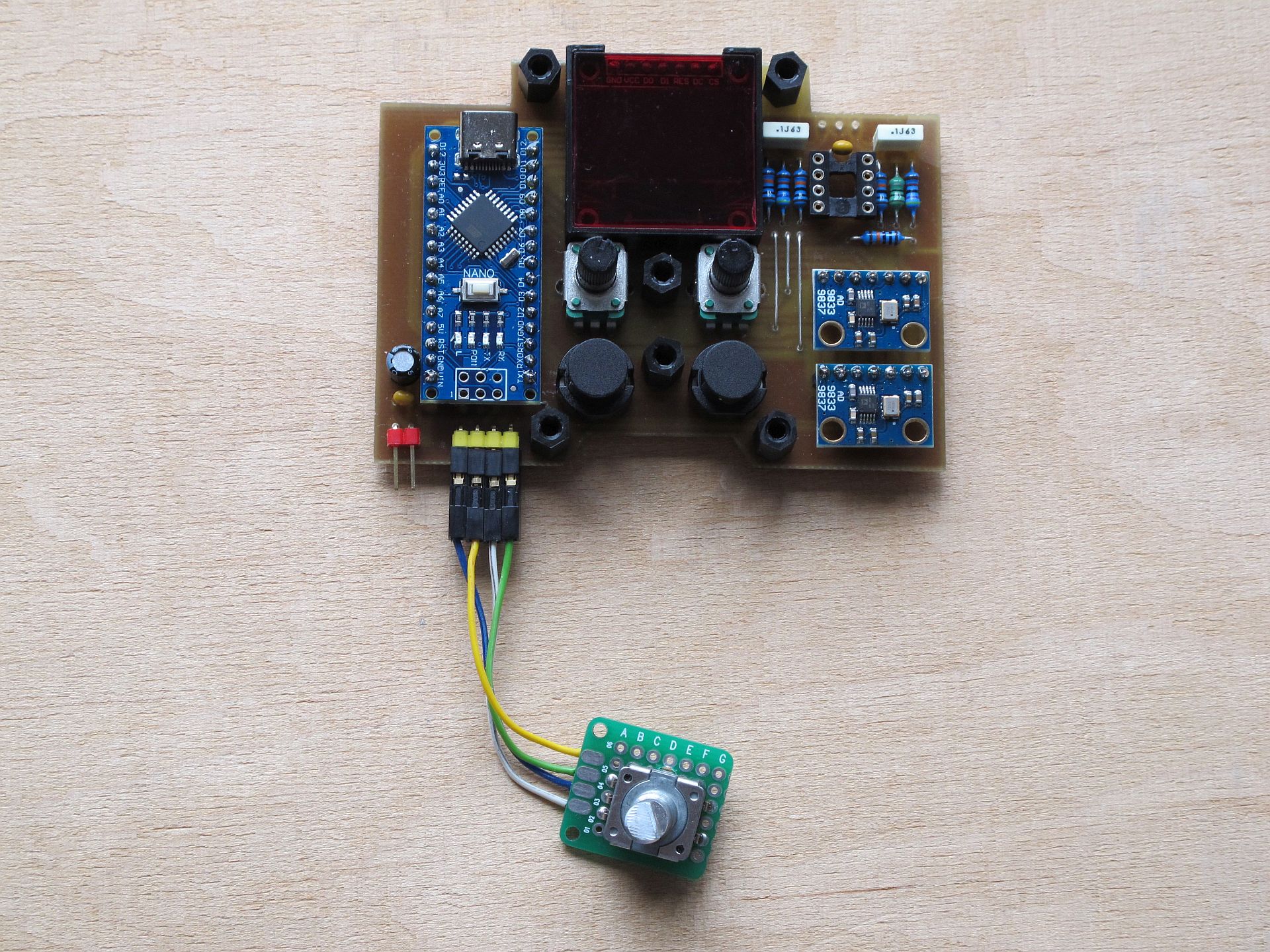
The circuit uses few components, mostly already soldered modules:
- Arduino Nano clone – the brain,
- two AD9833 programmable generator modules,
- OLED SSD1306 SPI display,
- stereo output amplifier (MCP6002 based) with additional HP filter and separate volume control (Alpha Taiwan RV09 series) for each channel,
- tactile user interface – encoder with button (Bourns PEC114125FS0018, 18 detents per rotation) + 2 mode selection buttons (Highly KS01-BV-BK).
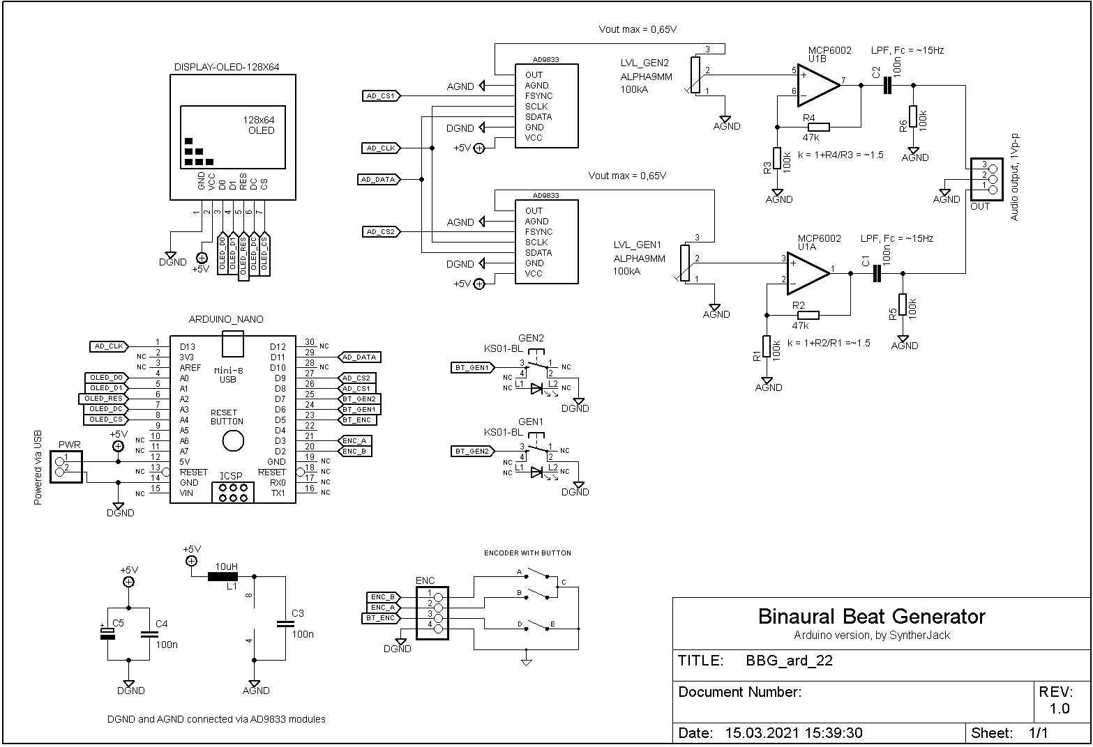
The logic core of my device is based on Arduino Nano, a small, cheap a popular ATMega328 microcontroller board. There are no complex calculations, so its limited processing power suits just fine. The most advanced task is controlling SSD1306 OLED display with SPI interface, but it also takes care of two Analog Devices AD9833 programmable waveform generators and handles encoder/button reading. As the generated signal levels are quite low, around 0,65 Vp-p, I used additional amplification 1,5x (basic opamp non-inverting application) to keep device output at the line consumer level (close to 0.9 Vp-p). Outputs of the amplifier are then high-pass filtered (C1, C2, R5, R6, cutoff around 15 Hz), to remove the DC component and protect against going too low (blown up speakers, remember?).
The ground is divided into analog (half of the AD9833 & output amplifier) and digital (everything else). Supply for output amplifier has additional filtering (L1, C3). There is no input protection, as the device uses USB-C which is standardized, and doesn’t have problems with accidental reverse polarity connection (at least it is hard to put USB-C into socket inversely). Nothing sophisticated is happening here.
The PCB
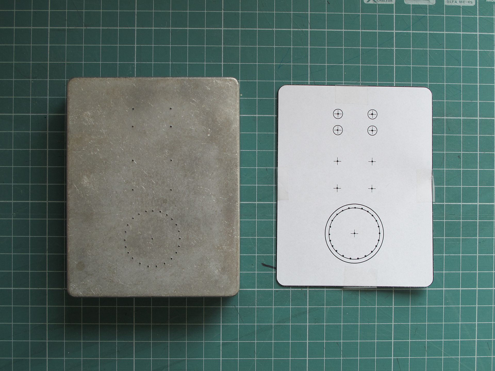
PCB and case are two elements connected in an endless circle of trial and error. Position of all interface controls on the front panel is limited by components size below it and overall PCB dimensions – that’s why my first step was an enclosure mock-up with all visible components – big jog dial, two buttons, 2 potentiometer knobs, and a 0,96″ OLED display (PCB and drill markers were added later).
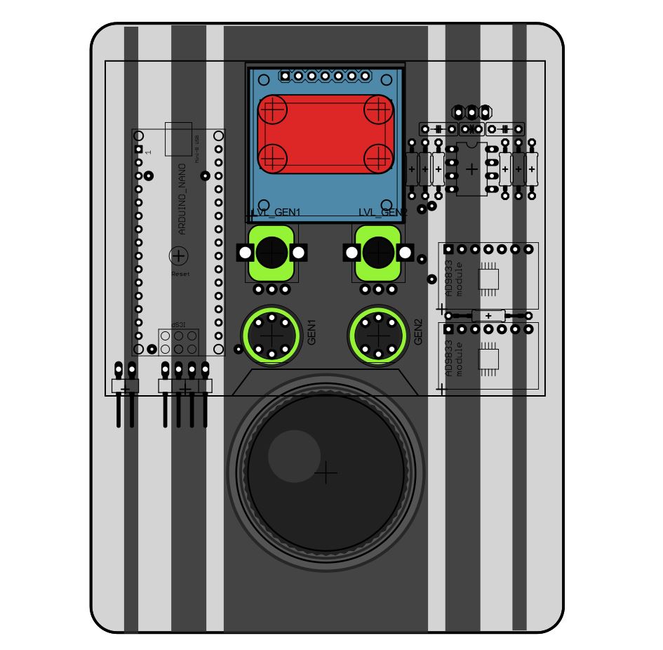
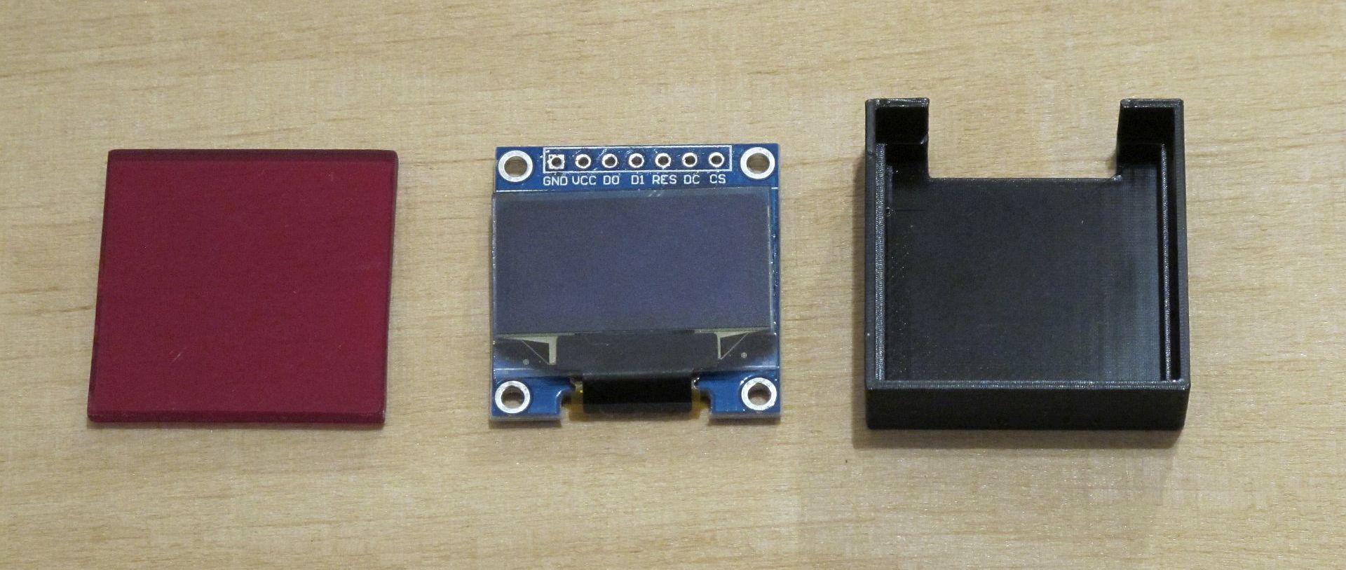
All components interface (except jog dial) are placed on the PCB, so no panel wiring is needed (yay!). I had a problem with the display, as it is not easy to fix firmly. With the help of my friend, I made a custom holder with a red filter. The combined display module has an exact height of 10 mm, so mode select buttons can be exactly 1,5 mm over the front panel. The Filter is 2,8 mm thick and dims displayed characters quite a lot (the price of deep, red color).
The PCB was designed in Eagle, then manufactured in my kitchen using the photo positive method. But first, it was printed on the paper to check if it fits inside the enclosure and if all component footprints are correct. It is also a good opportunity to place crucial components on the paper and check if the operation is convenient – f.e. if potentiometer knobs are not too close to each other.
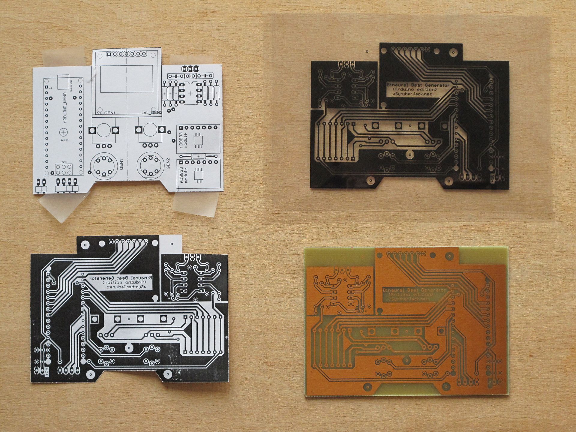
The left part of the PCB is digital (Arduino, display), right mostly analog (half of the generators, output amplifier). I tried to keep the connections in an analog part as short as possible to avoid interferences (I had a lot of problems with hum during testing the initial binaural beat generator prototype on the breadboard). The PCB is glued to the case with 6 nylon standoffs. As the most pressure will be transferred to the PCB via buttons, most spacers are located around them. Of course, not everything is perfect – the USB socket on Arduino is blocked by a (top left) standoff.
Along with the PCB, I tried to finish the enclosure.
The case – drilling
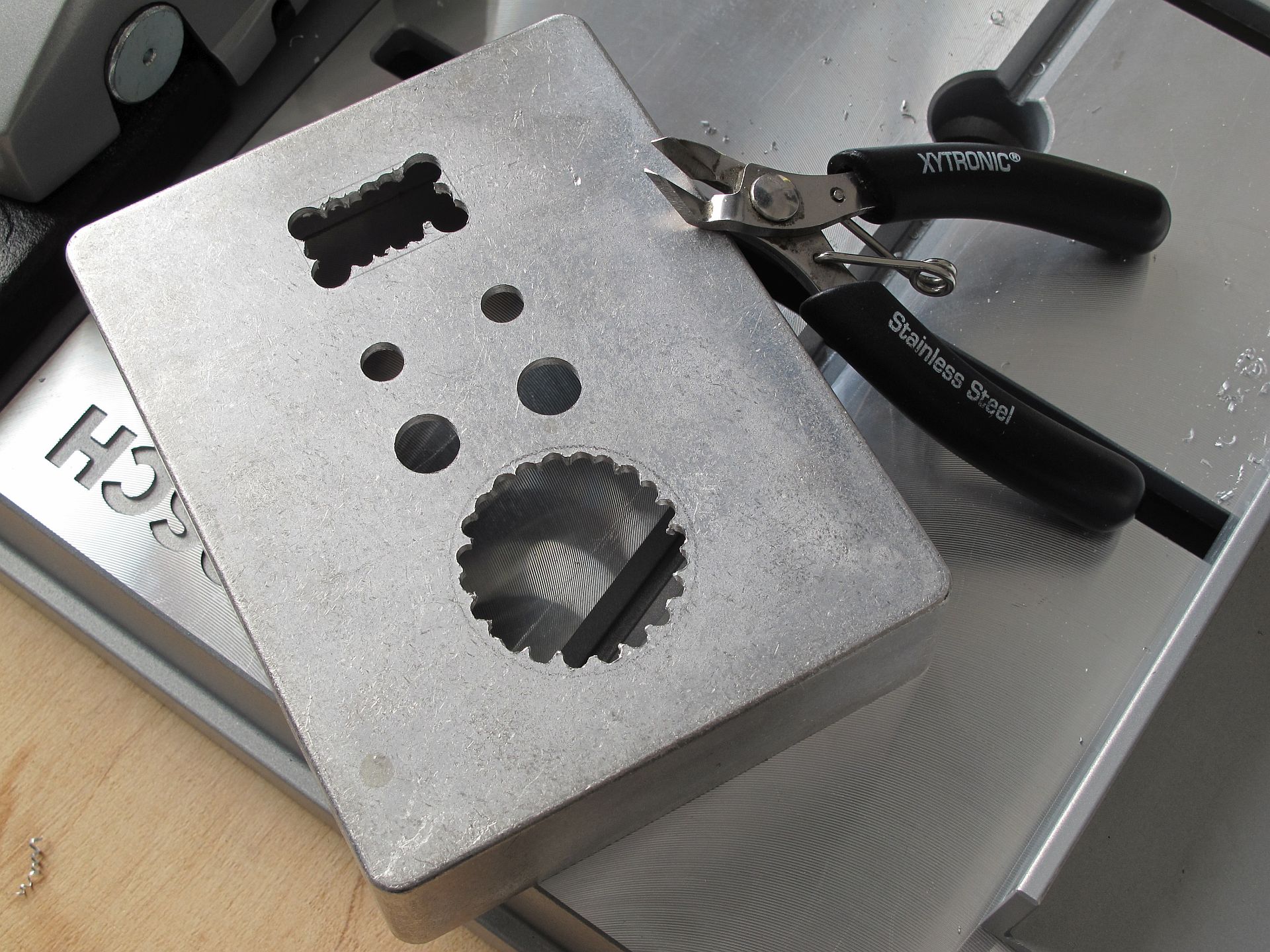
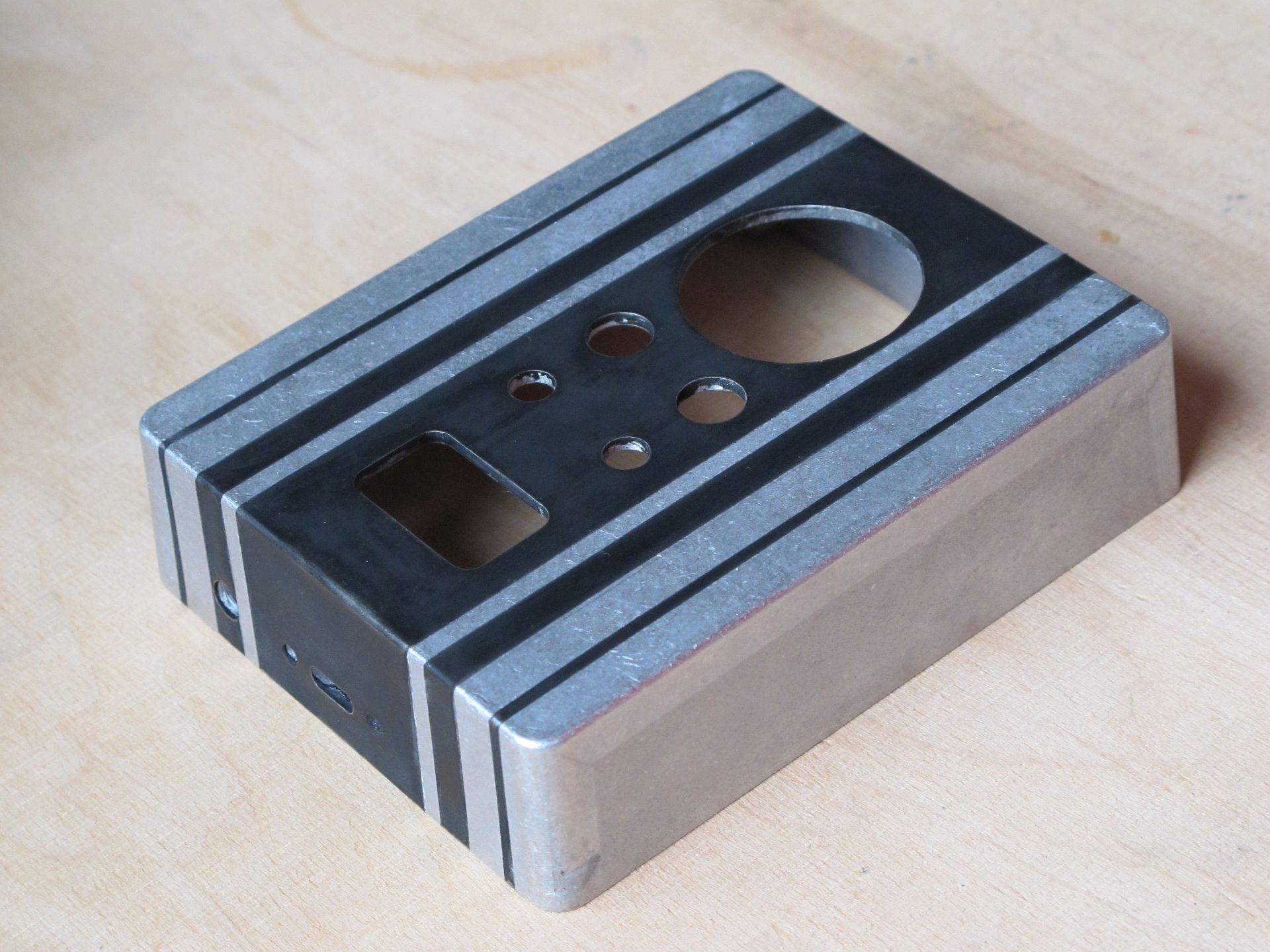
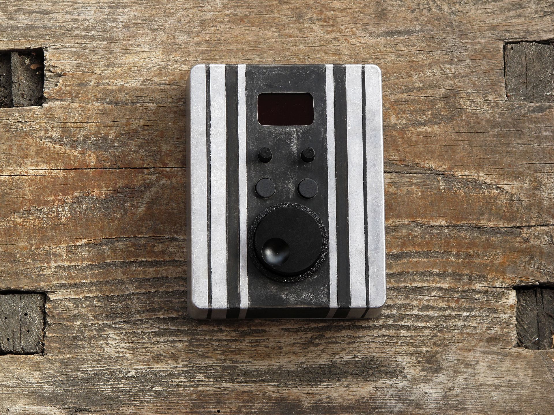
I bought a 1590BB style aluminum die-cast unpainted enclosure from Tayda Electronics. As I decided to go for a raw look, no additional sanding was needed (I know, great excuse). What is more important, aluminum collects fingerprints perfectly, which adds more rawness. After tough design decisions, using the Inkscape design, I printed the punching template, then punched threw it with a punch. And hammer.
This is my first case drilled with a press drill (Bosch PBD40). It is not ideal, but still a great improvement over the hand drill. The largest opening (for the jog dial) seems tough to cut evenly, but thanks to a clever 3D printed cover, the aesthetic was not so important (still, I prefer round-shaped, than egg-shaped ones).
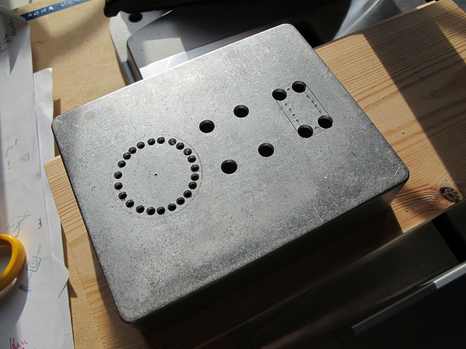
Now, please close your eyes and don’t follow the crime I committed. I found out, cutters are an amazing tool for merging smaller holes, so the crude opening can be shaped. I delegated my old Xytronic diagonal cutters ($4) for this job, and they serve their role for around 3 years now. Furthermore, I also prefer them over my Knipex ($35) for almost every electronics-related task, as they are very short (90 mm) and incredibly handy. I believe ProSkit makes very similar ones.
File job is a moment when my wife starts to scream at me. But it is necessary to keep the openings nice and clean. If possible, it is easier to design a corner rounding radius matched to the round file diameter. Now, as I look at the photo, I think I should leave the enclosure as it was back then – (reasonably) clean and elegantly gray.
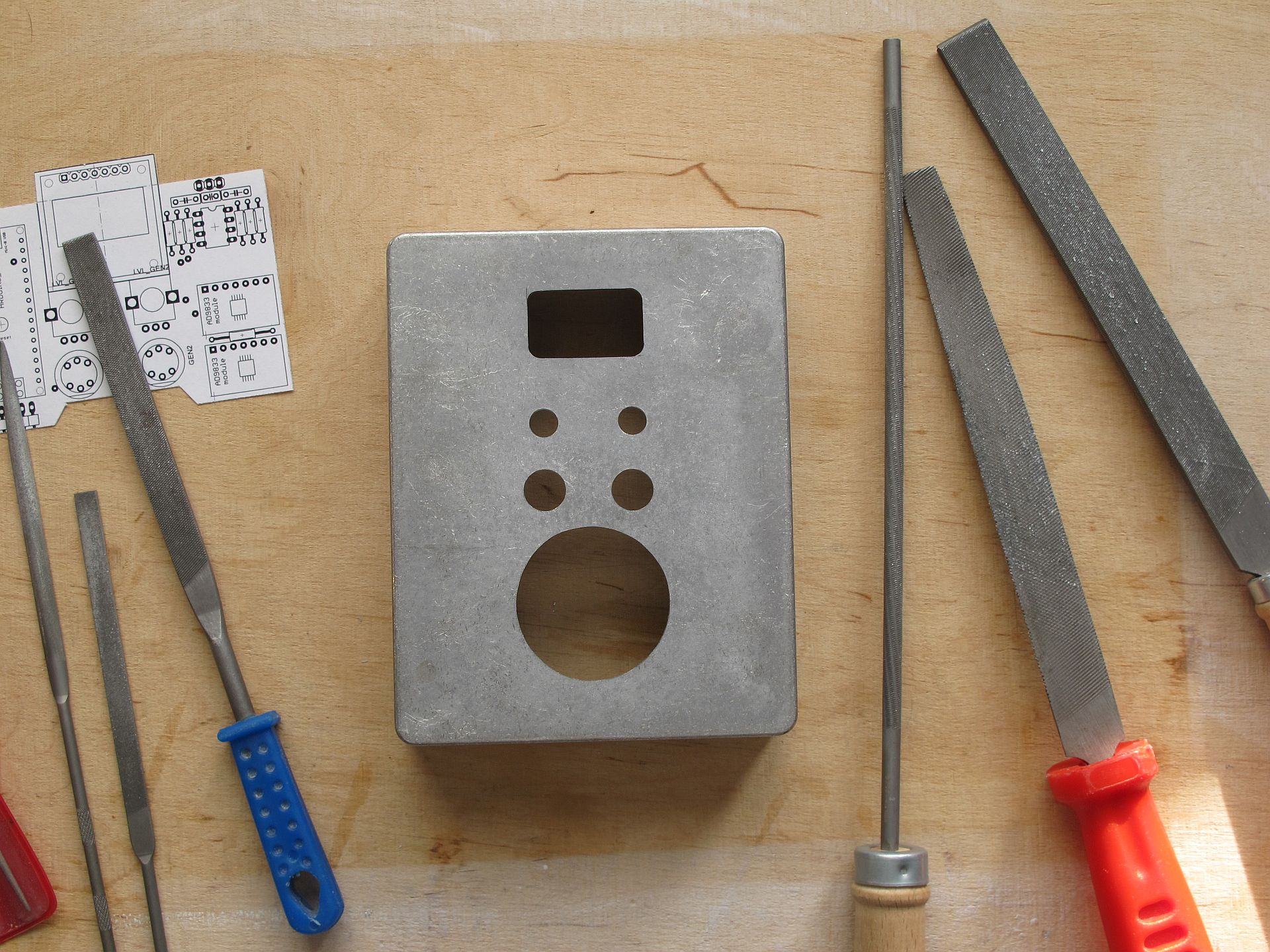
The final step was checking if everything fits together (especially display), and it fitted. The next steps were… questionable. I was happy to explore a new method of making the aluminum case more interesting, but I’m still not sure if I like what I did.
The case – oxidation
I wanted to try a process called “cold oxidation” – covering a metal surface with a layer of oxide, usually black, in a room temperature. So. I masked the part of the case with a double layer of thick insulation tape, exactly as the project I’ve created told me to do.
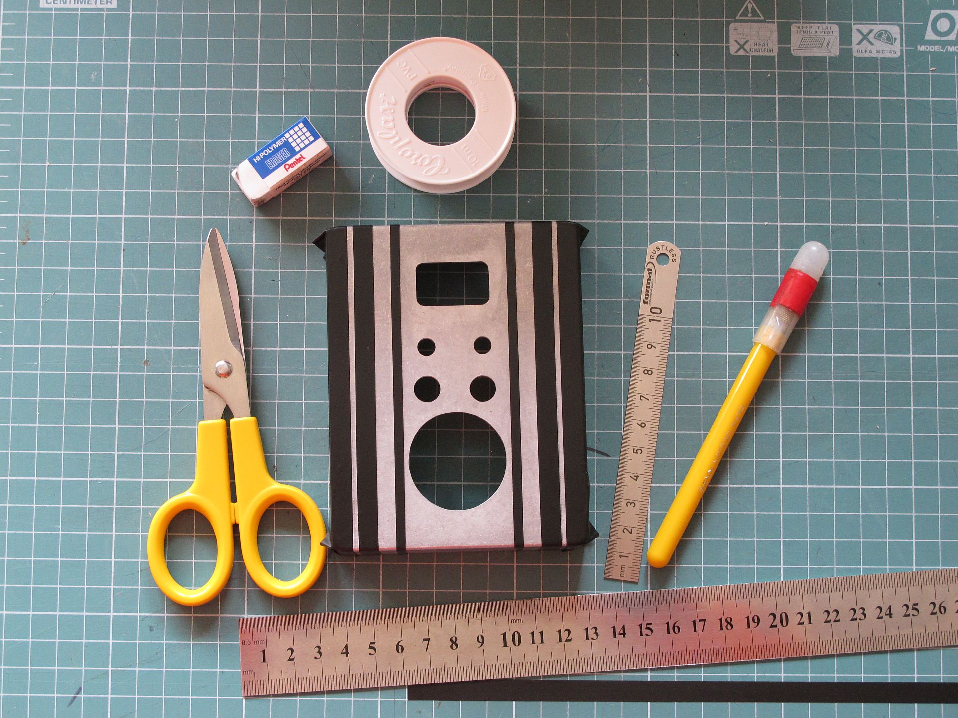
The next step was careful sanding to leave a clean aluminum layer, to make the job of the chemical easier. I used 2000 grade sanding paper for a crude, rotary metal brush for precise, then isopropyl alcohol (IPA) for the finish. A Double layer of protective tape serves as insurance, aluminum under it will not be touched (still at high brush rotation speed it may be damaged without problem).
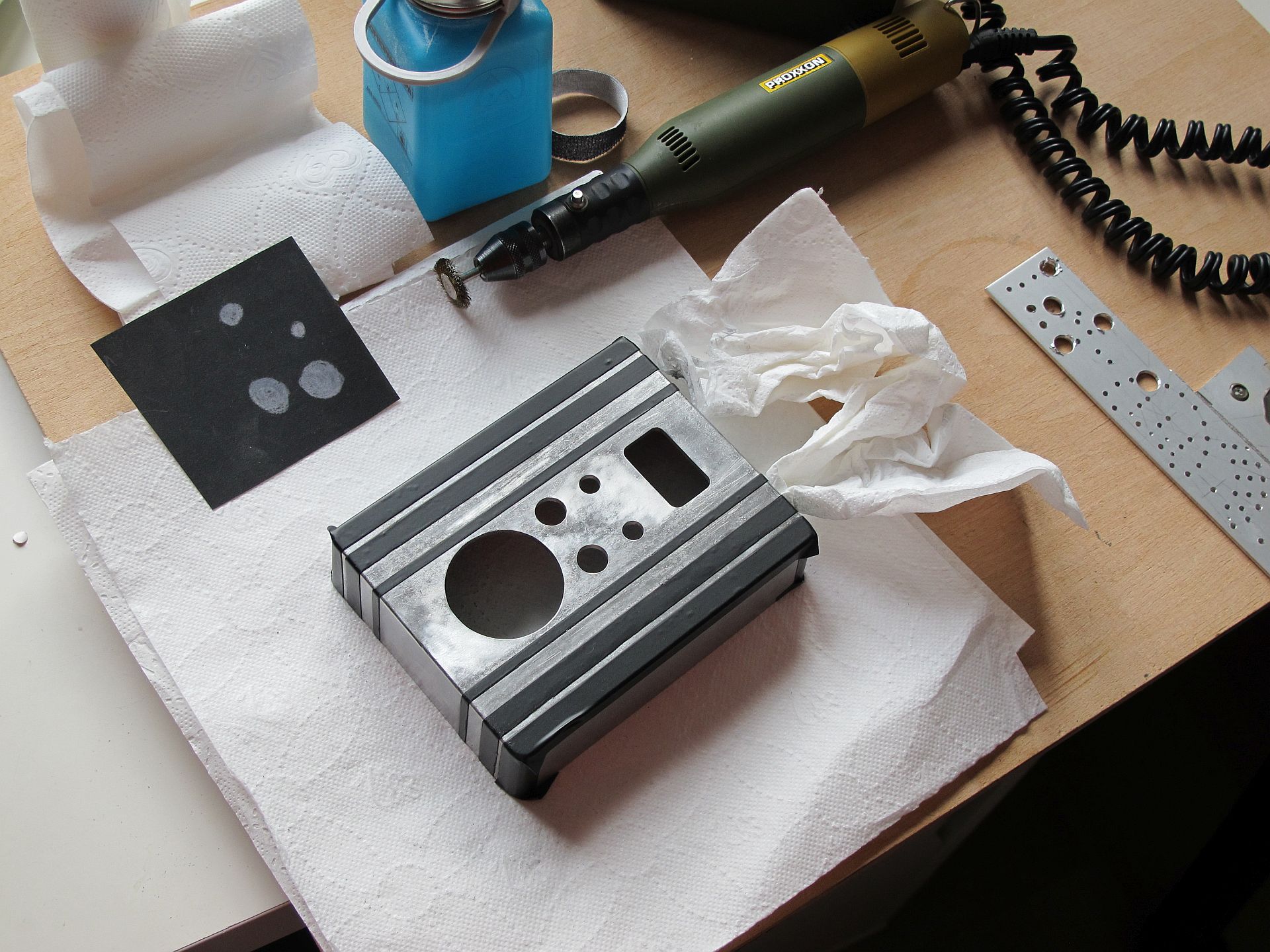
Using a small paintbrush I covered the polished and degreased part of the enclosure with NewComer brand, black aluminum oxide (a compound creating a black coating on aluminum). The case became black in a few minutes and my whole flat started to stink with rotten eggs (the magic of chemistry!). I wiped off any excess chemicals with a paper towel.
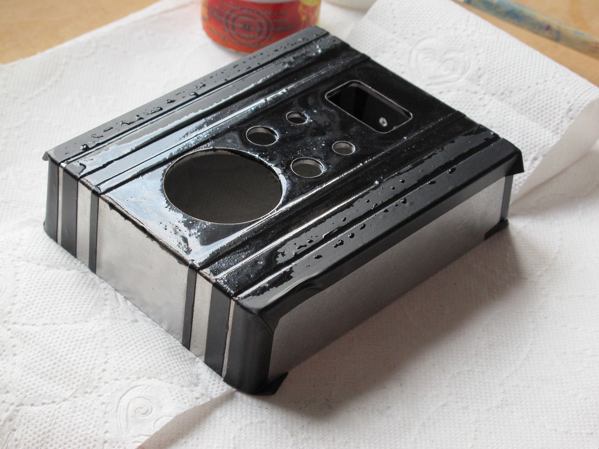
Back then I was happy, as the result seemed promising- the blackness was dull and deep, with slightly visible discoloration. As it was hard to oxide the internal edges of the holes, I later improved it with a black marker.
There was one thing I didn’t take seriously enough. Written in small letters on my aluminum oxide package: “Blacken aluminum objects that do not require a high degree of abrasion resistance”. I thought: “it’s fine, I don’t need a high degree of abrasion resistance.” But I also didn’t think, I will be able to scratch the coating with my fingernail :/ And by “raw look” I rather thought about “classy rusty hot rod look”, rather than “rotten bike out of a lake look”. My fife told me, she would do better with acrylic paint. If you are curious about the final result, photos of the finished device are at the very bottom.
Dávať dokopy
One more part was missing – jog dial/encoder holder. I designed a special insert so that the dial does not protrude too much above the panel surface. This way generator seems more compact and still, you can rotate the jog dial quickly with one finger, or set precisely holding to the side. The other reason was, making an opening so large with hand tools is hard, and a small rim masks uneven edges perfectly (bottom left part on the photo below).
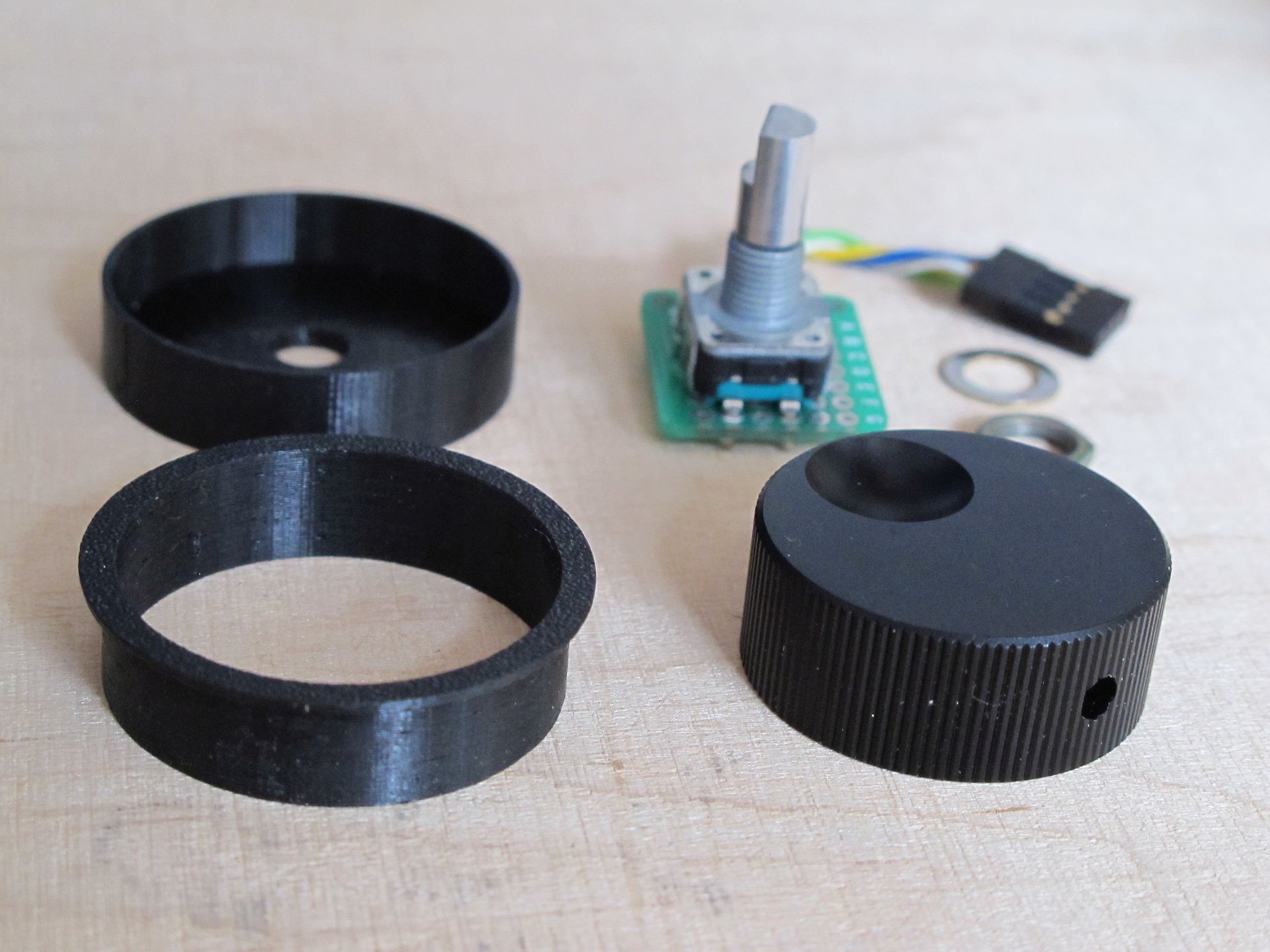
I sanded and degreased spots inside the case where spacers supposed to be glued and fixed them with the AutoWeld two-component epoxy resin. The conductive surface of the PCB is covered with a layer of protective lacquer (Kontact Chemie Plastik 70) and screwed to the spacers with nylon screws. Encoder and output Jack are connected using small universal PCBs for extra tidiness.
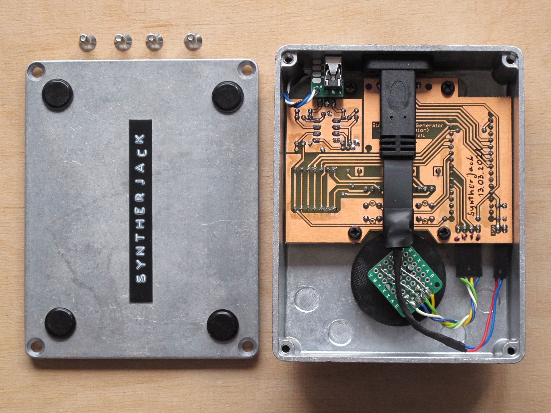
The bulky USB-C connector was originally a part of PC rear panel motherboard USB expansion, the only cheap way to put my hands on a panel-mounted USB-C socket (look for “USB 3.1 Panel Motherboard Expansion Cable“). At first, I just wanted to use a USB socket build-in Arduino Nano, but then I would lose some freedom of placement (not to mention the holes would have to be drilled perfectly).
The code
I used the Arduino platform to program the Nano, the code is around 650 lines long. Most of it handles edge cases related to different operation modes, but the conversion from frequency to note symbol (with cent offset) was the most difficult task. The Arduino sketch can be found here.
Operation
After powering the device (plugging USB), the welcome screen is displayed and the device goes into one of the three modes, differing in a way of entering the generators operating frequency:
- First mode – most obvious one, you set the frequency of each sine generator independently; useful, when using binaural beat cheat-sheet and want to set f.e. 450 Hz on the first generator and 454 Hz on the second (top left).
- The second mode – frequency and offset; great for experimentation, when f.e. you want binaural beat frequency in a theta range (0.1 – 4.0 Hz) and looking for suitable base frequency; in other words, you change frequencies of both generated sines at the same time, and offset between them is kept at the same, selected level (top right).
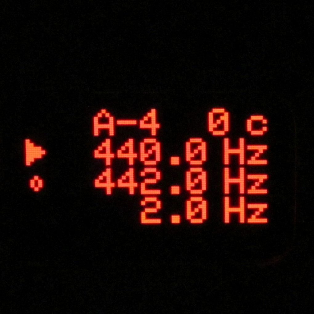
- The third mode – note and offset; a mode asked by a friend to easily add a binaural beat to existing ambient track; just set base note (f.e. C-3), binaural beat frequency (that is offset, f.e. 0.8 Hz) and you are ready to relax the crowd! (bottom left).
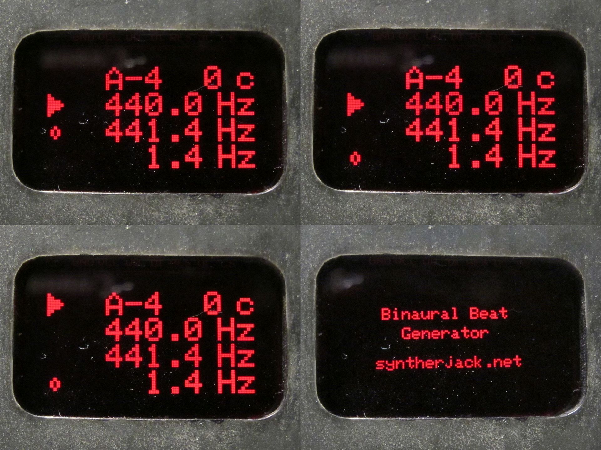
No matter which mode you are in, after pushing the left button you will set the left channel generator, right button – right channel generator. The active selection (parameter you change with jog dial) is marked with triangle, inactive parameter (the other generator) with the empty circle. By pushing the jog dial, you are switching between fine (0,1 Hz/detent) and coarse (10 Hz/detent) setting mode. By pushing two buttons at the same time, you go into the mode selection screen, described below.
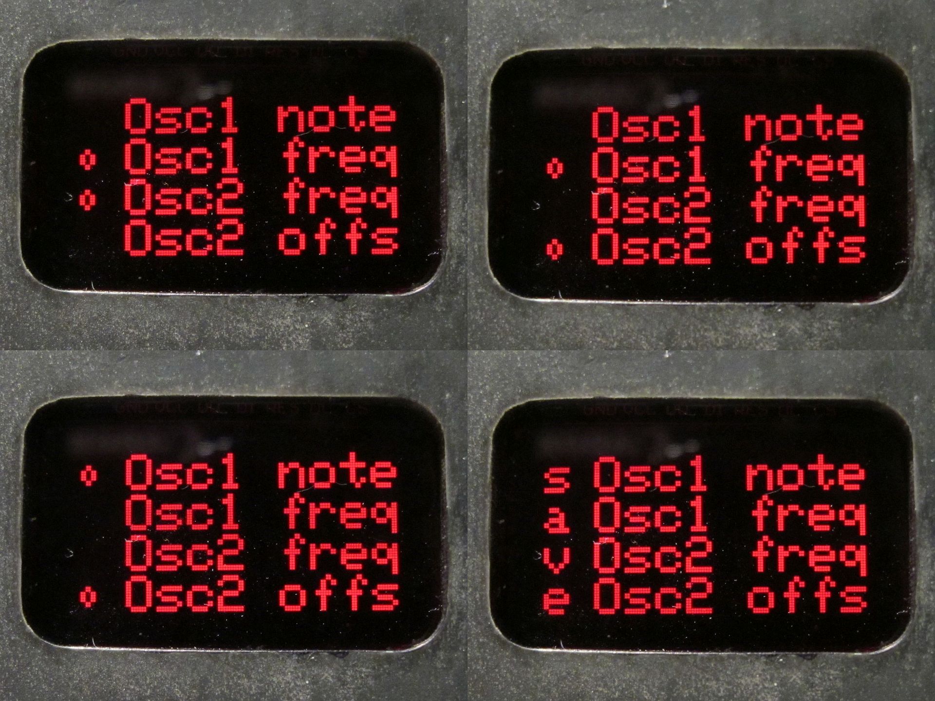
In the mode selection screen, names of all available binaural generator parameters are presented – you can choose one of three pairs of parameters (marked by two empty circles) or save active settings (they will be loaded on devices startup).
Specs
Mechanical:
- size: 90 x 120 x 45 mm (with knobs),
- weight: 300 g.
Electrical:
- power supply: +5 V/50 mA, USB-C,
- power consumption: ~0,25 W,
- output: 0,9 Vp-p.
Audio:
- waveform: 2x sinewave,
- frequency range: 30 – 1000 Hz,
- THD: typically 0,05 % (according to AD9833 datasheet),
- setting resolution: 0,1/10 Hz (1,8/180 Hz per jog dial rotation).
Demo & final thoughts
The raw look became a bit too raw after a week of use, as the oxidation layer began to wear off. But at least I am happy with the UI – it is simple and a pleasure to use. Jog dial rotates smoothly and you can feel its weight and sturdiness. Going from analog to digital was an improvement – the generator lost a bit of mojo, but the accuracy, THD, ease of tuning improved significantly.
The demo was doomed to be boring, boring as a sine.
As a proof-of-concept, an Arduino-based binaural beat generator is much better than I’ve expected. If you want to build one – feel free to, it should cost below $20.
Cheers,
Jack
Hi Jack,
great project and smart design. Are you going to post the PCB files ?? Both of your download links
only give you the Arduino code.
Looking for a unit for sale.
Hi..how can I purchase this?