Stay calm, this is simply the beginning
Durning my early synth DIY days I made a lot of simplest stuff – all kind of “beginner friendly” projects. They were cool devices to make, but after an initial exciment phase, a reflection came – they make some bleep sound and thats it :/ (It think the first device I really liked and still amazes me is the MFOS Echo Rockit). So that cold, winter weekend I decided to design a simple device that won’t be a instant sonic fail 🙂
My target was to create a very simple synth using only 1 IC. I already had a small verified “synth-related simple schematic collection”, so I grabbed a beer and started to wiggle. I wanted to implement circuits thats are universal, simple and good sounding. It was not an easy task, as those things are mutually exclusive. So, i’ve started with some initial assumptions (it is nothing worse then looking at your freshly designed synth and thinking you wanted to build something else).
First of all I wanted to determine cool synth sounds that everybody love (and are easy to implement), because they will impact the synth architecture. We all like (ok, most of us):
- filter sweeps at high resonance,
- filter with LFO to CUTOFF modulation, for wooa-wooa-wooa effect,
- pulse width modulated squarewave,
- detuned, beating generators.
The second thing – user interface. What I always missed that with simple devices I was unable to play even most simple melodies (like 66% of Monotron series). Therefore user interface should contain a lot of knobs and some sort of usable keyboard.
Finally, the hardware. Synth should be cheap and easy to solder with no more then 50 readily available components. Maybe it should have a build-in speaker? How it will be supplied (9V battery, USB)? The “1 IC” limitation was just an additional challenge (added for my strange pleasure of solving problems).
And this was my starting point. A piece of cake.
Totoro hardware ideas
The first shot for my simple synth heart was PT2399 delay IC, but I wasn’t happy with it (later I used most of designed circuit in Jackyll DIY synth, I will describe in separate post). The second idea was more straightforward – a quadruple operational amplifier. Good for generators, filters – just everything. That’s how heart of Totoro was chosen. The synth was named after my cat, and my cat was named after a character from “My neighbour Totoro” movie. You can say, this synth is like my cat: simple and dirty, but with big heart 🙂
I’ve ended with very straightforward architecture – 2 generators and a filter:
- OSC1: squarewave audio range generator with tunable, 3 – button keyboard (you can play up to 7 different pitches when using combinations of buttons),
- OSC2: square-, saw-, trianglewave generator with audio / LFO range (OSC2),
- VCF: lowpass with 2 resonance levels and cutoff optionally modulated from OSC2.
Block diagram (in Monotron Style) should clarify everyhing.
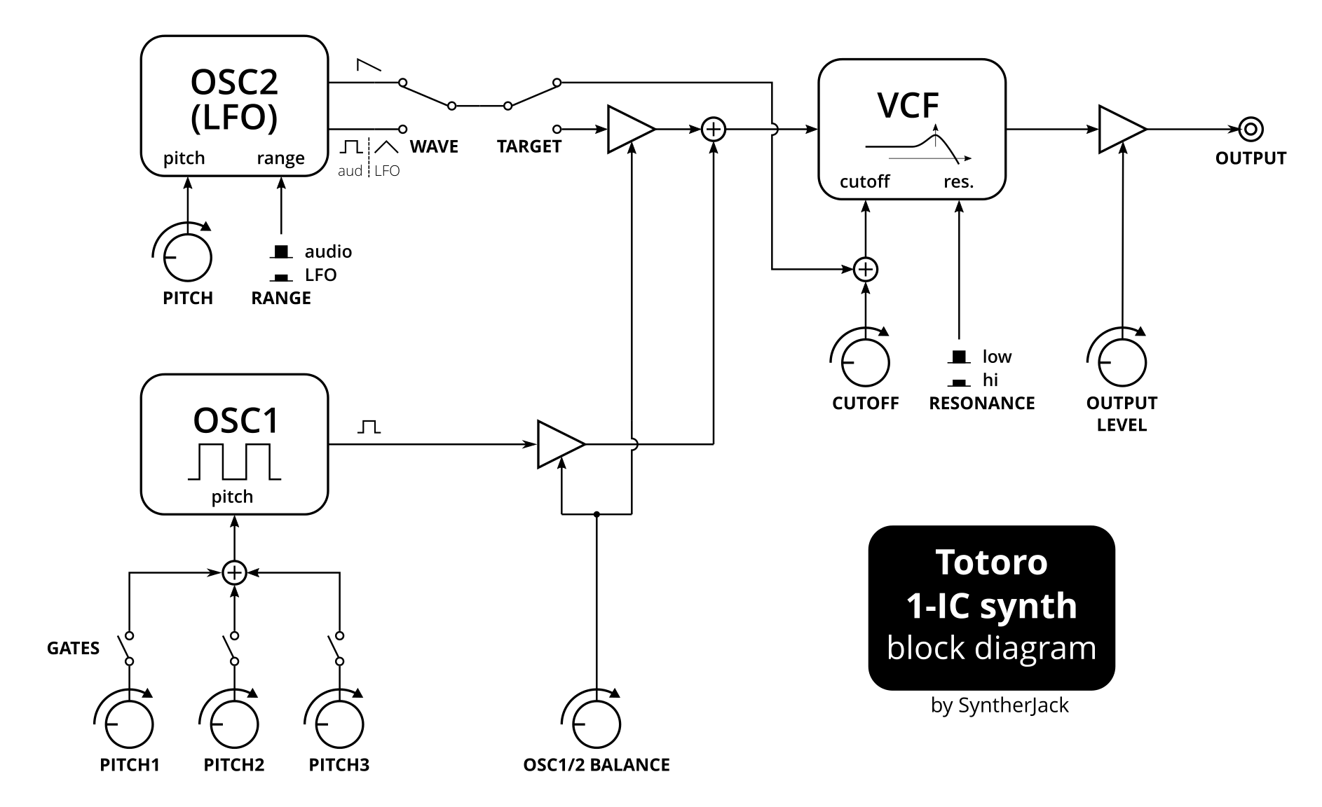
Maybe it looks not very promising, but remember, this simple synth uses only 1 IC (and 1 transistor). Lets dig into the details.
The Totoro schematic
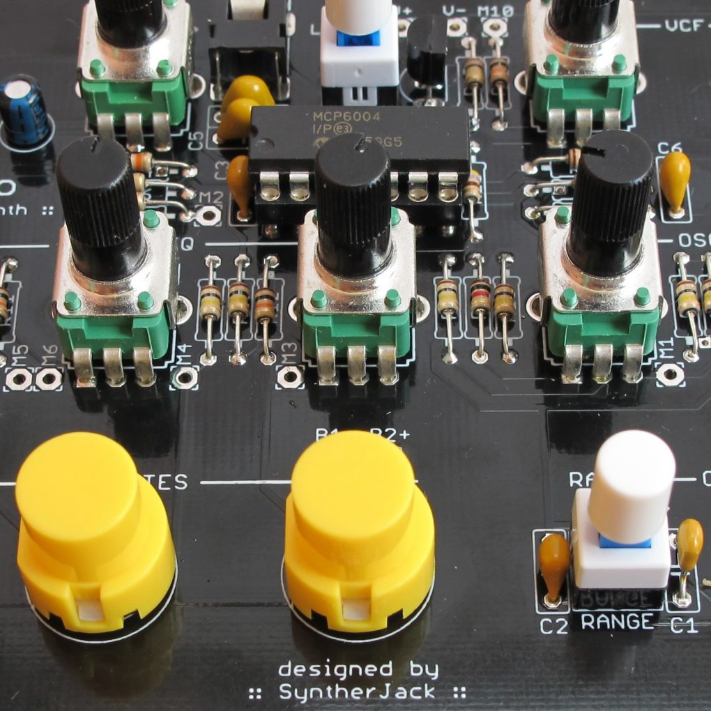
The final schematic of the device looks as following. Like I planned – below 50 parts! (In fact, if you willl breadboard it without 2P2T switches it would be closer to 40). I tried to make it as beginner friendly as possible – most of the resistors and pots values are reused, and there are only 2 parts that can be potentially damaged: opamp and transistor, both are using sockets for easy replacement. There are also an additional mod points (M1-10), so you can extend “keyboard”, add oscillator sync-like feature, external VCF audio and CV inputs and more! I tried to use good quality components where possible. Pots are Alpha Taiwan, yellow switches from Omron/Highly, Jack socket – Lumberg. The filter is very crude by design, so I used ceramic capacitors instead of preferred polyester type.
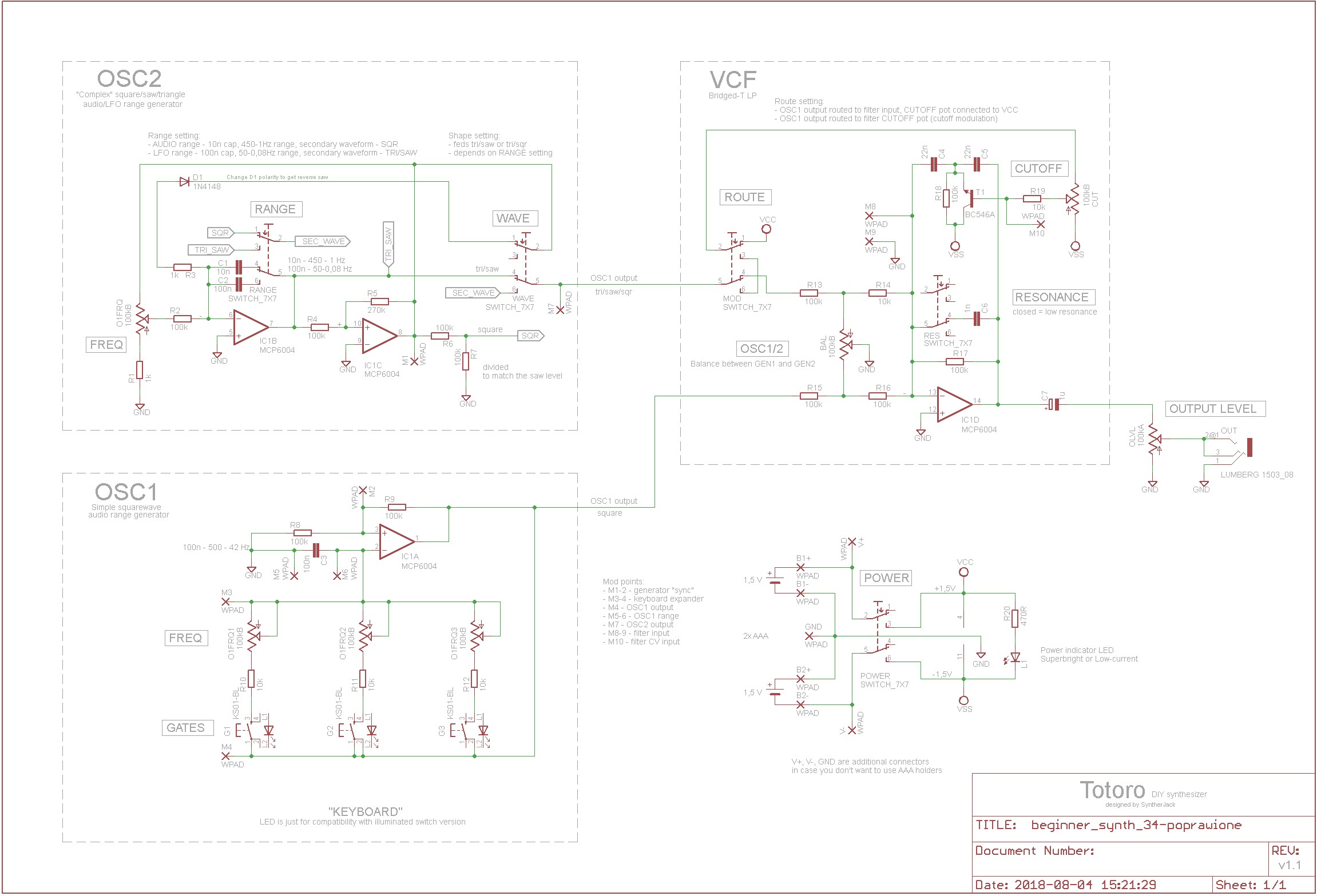
OSC1 is a very simple, single opamp based squarewave generator. If no key is pushed, feedback path is opened (R10-12 resistors with pots), so C3 cannot be charged (or discharged) and the generator is stopped. As you push one of the buttons (GATES), C3 is charging via corresponding resistor/pot (FREQ) network and the whole thing starts to generate audio range squarewave. Expanding keyboard range to f.e. one octave is not a problem – just add few more resistor/pot/switch sections to M3/4 mod points! To change whole generator tuning you can use M5/6 mod points.
OSC2 is more complex and is build around triangle/squarewave oscillator with additional discharge path (D3/R1) to get negative sawtooth waveform (negative ramp) and R6/R7 divider for squarewave output to match saw/triangle level. OSC2 can work in 2 modes chosen by RANGE switch – AUDIO and LFO:
- AUDIO – 10nF timing capacitor, saw- and squarewave (waveforms with a lot of higher harmonics) are send to output,
- LFO – timing capacitor switched to 100nF, saw- and triangle waves are generated (as they feel like a good choice for modulation purposes).
VCF is designed around T-bridged filter topology with crude CV input added via T1 transistor. There are 2 resonance values you can choose: gentle and wild (when dumping C6 capacitor is disconnected). CUTOFF potentiometer serves as standard cutoff control if there is no filter modulation (OSC2 is fed to VCF input via ROUTE switch) or as modulation depth control if OSC2 is used as modulation source (ROUTE in lower position). Set of R13-16 resistors with BAL potentiometer matches levels between OSC1 and OSC2, also serves as balance control between them. You can for example set OSC2 to modulate VCF cutoff, then set OSC1/2 balance to hear only OSC1, not OSC2 working as LFO. I admit the filter is based on design I know form WP-20 from Waveform Processing with some small tweaks. I tried to simply even more and ommit the transistor, but this made the CUTOFF potentiometer response very nonlinear which didn’t feel right.
To get rid of all biasing circuits, I made power supply for Totoro symmetrical and used LM324 quad opamp, which runs on +/- 1,5 V, perfect choice for battery supplied device. In later designs I used MCP6004 quad rail-to-rail opamp and minimum +/- 0,9 V operation (you have to remember, AA/AAA battery output voltage will drop below 1,5 V after some time, also with lower supply demands you can use 1,2 V accus). The other advantage is, with +/- 1,5 V you will get maximum audio level just below proffesional audio level (which is +/- 1,736 V), so connection to a audio mixer will probably be harmless (there is also no need for any additional output level limitation except simple potentiometer).
PCB design & stuff
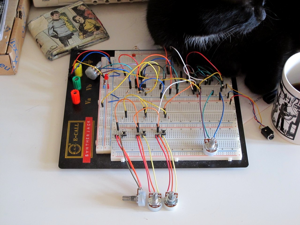
The first Totoro prototype (the one on the protoboard) was working correctly, so I moved to PCB. I tried to design it below 100×100 mm to get good fabrication prices and keep sufficient distances between potentiometers. For 6 mm shaft Alpha pots (and other controls) I kept the distance around 21 mm between centers – slightly over the value Korg used in their Monotron line (17 mm). This assures synth operation will be (hopefully) painless even for bigger fingers.
My second Totoro prototype (photo below) had some issues – I had problems matching OSC1 switches with caps (most of them were not high enough to put any enclosure). I also left too few space for AA battery baskets – back then I imagined I will use 2x AA batteries and place them vertically (B1 and B2 points).
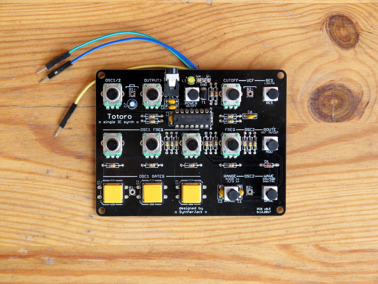
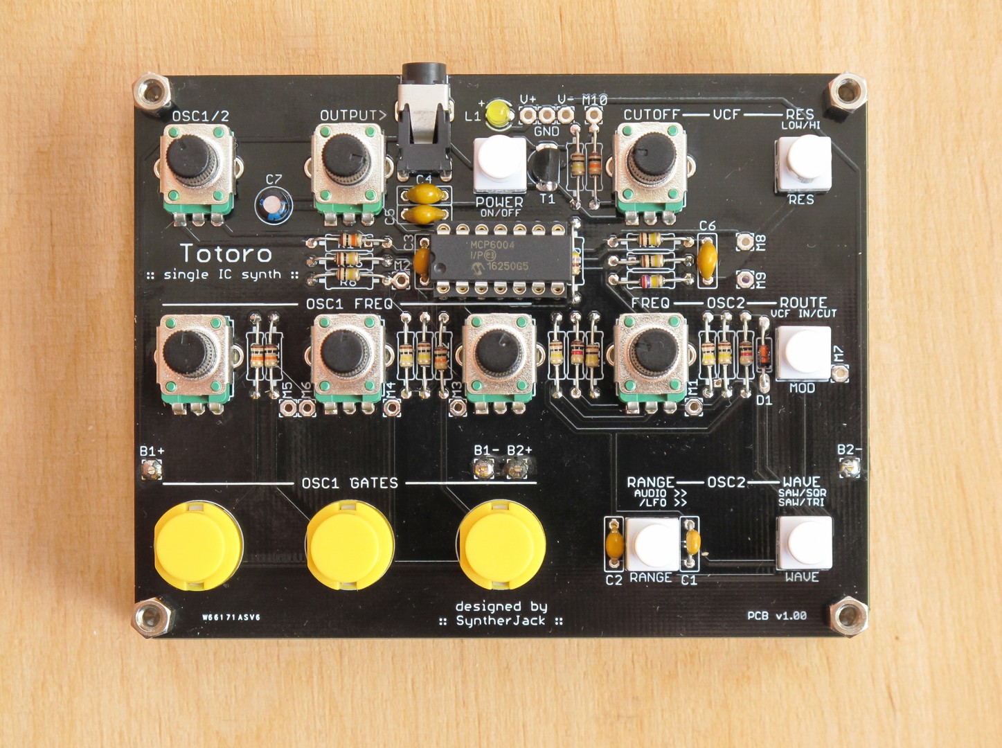
In the third prototype (2 incoming photo shots) I used 2 AAA battery compartments placed horizontally under the potentiometrs, also changed the GATES switches types from Omron B3F series (with caps) to Highly KS01, which fit perfectly but have slightly worse tactile feel. Unfortunately I made an error durning design – 2 traces were overlaping, but can be repaired.
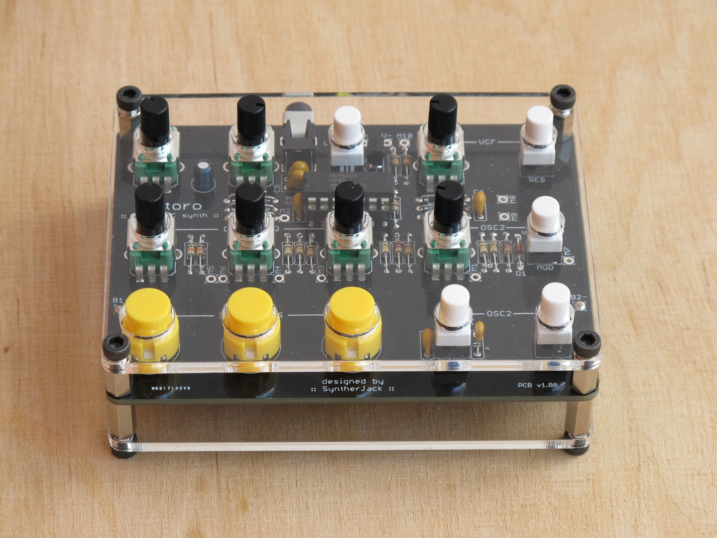
I made the cover with 3 mm plexiglas, 8/12 mm spacers and sexy black hex screws. They have knurled edges and you can fix them using only fingers.
The final version will be close to the last prototype, but (I hope) without overlaping tracks on PCB . I will also add pads for Omron switches, as they can became handy in future builds – f.e. without plexiglass enclosure.
Boring technical details
Synth architecture & controls:
- OSC1:
- squarewave,
- frequency range: ~500 – 40 Hz,
- 3x keyboard TUNING potentiometers,
- 3x GATE switches,
- OSC2:
- WAVEFORM (square, triangle, saw),
- RANGE (“audio” ~450 – 1 Hz / LFO ~50 – 0,08 Hz),
- TUNING potentiometer,
- TARGET (VCF input, VCF cutoff),
- VCF :
- bridged-T topology,
- CUTOFF potentiometer,
- RESONANCE switch (low/hi),
- mixer:
- OSC1/OSC2 BALANCE potentiometer,
- output LEVEL.
Mechanical:
- dimensions:
- PCB: 76 x 100 mm,
- without pots: 76 x 100 x 28 mm,
- with pots and screws: 76 x 100 x 40 mm,
- weight (with battery): 143 g.
Electrical:
- power supply: 2x AA (down to +/- 0,9 V with MCP6004).
Demo & final notes
I don’t want to lie it sounds like Moog or Arp – it is just a device that sounds good for what it is – cheap and easy to build synth. With a little bit of good will you can say it is close to Korg Monotron line, but without MS-20 filter. And build in speaker.
I think thats it. Hope you liked my little, dirty project! Build it if you like, it is very easy to breadboard. All info you read is for non-commercial use only (licence: CC BY-NC-SA).
Cheers
Jack
Could you release board file (Eagle as I can see by schematic outlines?) and BOM as well?
Hi there, we’re just embarking on building our Totoros (thank you so much for sharing!) and I was wondering about the mod points.
This is my first synth build ever (v excited!) but I do have some other synths that can send CV and would like to add a clock sync. You mentioned that that’s possible but could you explain it in a bit more detail please?
Many thanks!
Hi syntherjack,
We’ve been very inspired by your design and extended it a bit, keeping it simple, but adding voltage control on filter, oscillators and LFO making it Eurorack compatible. Everything stayed open source and is on Github, including KiCad schematic and layout. https://github.com/chairaudio/ILSE
I hope you like it.
Max