It was back in 2014. Thanks to user hidden behind wutierson nickname I managed to finish digital “metallic” sound generator based on the one used in Simmons SDSV hihat / cymbal drum modules.
The story
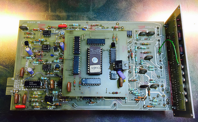
SDSV drum brain was shipped with only 5 modules – bass, snare and 3 toms. Hihat didn’t belong to the standard set. If you check demos of this device on YouTube, you will notice 99,9% of drummers don’t have hihat module and use standard, 100 % analog, metal hihats. One reason for this – hihat (and cymbals) modules are hard to find nowadays and sound a little strange, very mechanic and metallic. Therefore the reconstruction of this module was out of my range – I had almost no data, it was even hard to find a good quality PCB shot (the one below is from 2016, 2 years after I needed it).
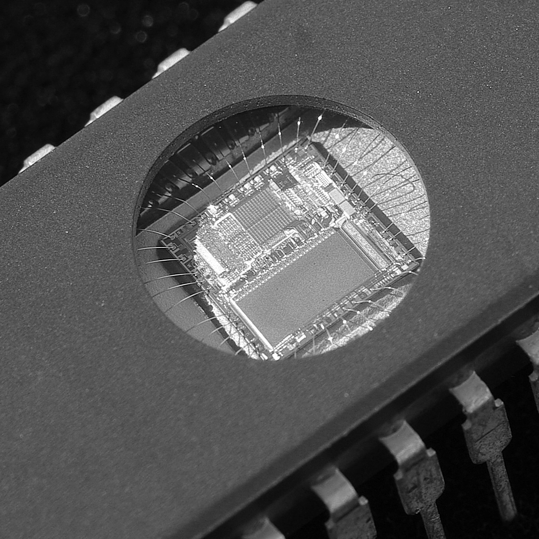
The original hardware
You can say SDSV hihat is a modified stock SDSV module. An additional, smaller board was placed on the top of standard, analog board. It is a digital waveform generator and the big IC with glass window is EPROM memory containing playback data.
This addon has only one input – CV voltage controlling generators pitch and one output – hihat waveform (without any amplitude envelope, just constant sound). Even without trigger signal, generator is working. Noticable thing is that the sound is played back in unusual way – a “ping – pong” – forth and back in a loop. The question is…
How it worked?
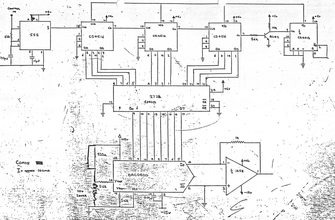
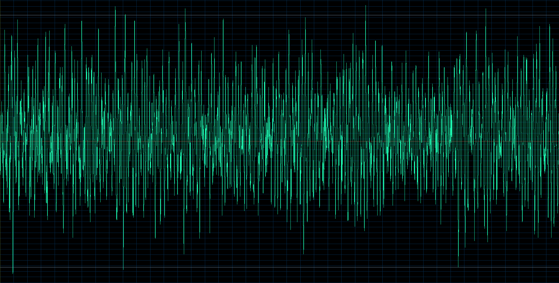
In original circuit, 555 timer (top left) generated a squarewave waveform – a clock signal for series of CD4516 counters. CD4516 is a presettable up/down counter – the counting direction can be controlled via external signal on pin 10. Each of those 3 counters outputs a 4-bit value to the 2732 EPROM IC and a 1-bit value to the next IC on its right. The last of them, the CD4013 is a dual D flip-flop and is responsible for counters direction. So, the value, 12-bit address going to the 2732 is changing from 0,1,2 … to 4095 then 4094, 4093 etc. to 0 and a whole cycle repeats. 4 kB EPROM holds 4096, 8-bit samples data and outputs them, corresponding to given address. The waveform hold in EPROM is rather complex (definitely not one period – see picture below). Then, the DAC0800 converts digital signal to analog, we can hear as hihat waveform. The frequency of the 555 generated clock varies depending on voltage level on the CONTROL IN input from 2 to 100 kHz. For example, at 25 kHz generator frequency sample length is equal to 163 ms.
The “cloned” hardware
Cloning the original was a bad idea because of low availability of the components. The circuit was mostly digital, so recreating its behaviour should not been a problem (silly me!).
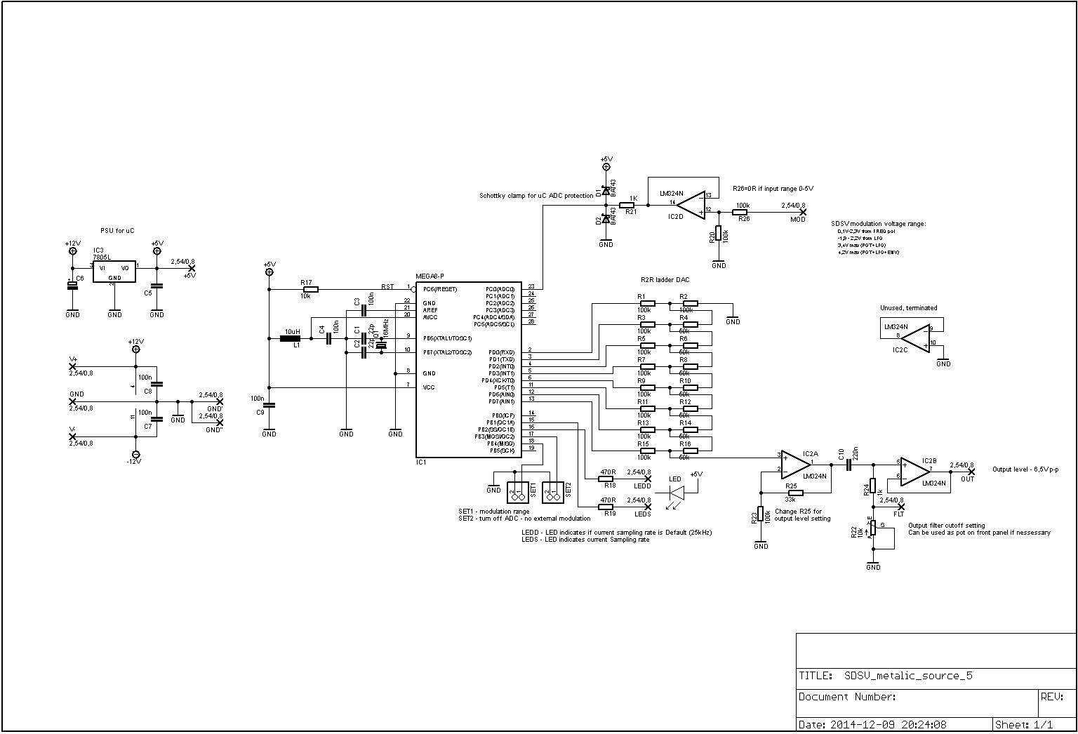
In my circuit I used popular Atmel ATMEGA88A microcontroller running at 16 MHz, replacing 555 squarewave generator, counters and EPROM. 8 bit output (pins PD0-7) is send to simple resistor / buffer R-2R DAC. The sampling frequency by default is 25 kHz and can be changed via CV input (so it can be modulated via existing SDSV LFO, envelopes or external CV). CV input accepts 0 – 10 V levels and protected with D1/D2 Shottky diode clamp. The LEDs on PB1 (marked as LEDD) indicates waveform generator frequency – LED is lit for 1 waveform period, then turned off for 1 period and so on. The LEDS on PB2 pin indicates default sampling rate occurence (25 kHz). The two LEDs was used mainly for debugging, but can be placed on front panel also. The simple RC high pass filter on output let you to cut lower end for more hi hat-like sound.
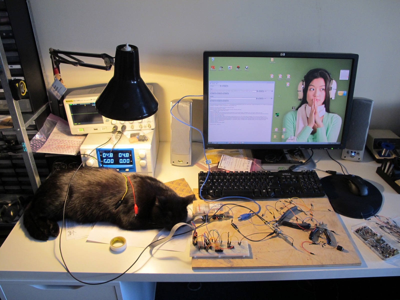
Some shots from development. The hardest part was to hide breadboard from my cat. Anytime he saw it, he pulled out wires.
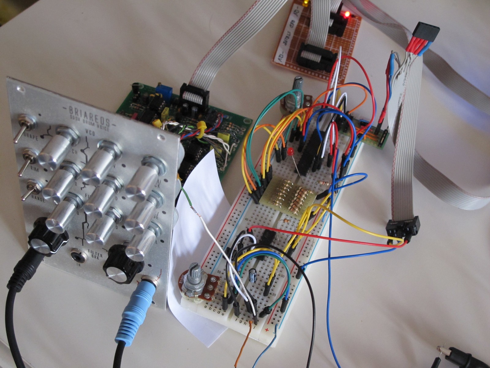
The breadboarded prototype was wired to working SDSV clone – the best way to check everything is ok (or burn it). The small PCB is a R2R resistor ladder – to avoid excessive mess, also used in my other projects.
The software – CV response problem
First of all the output of the digital PCB from the original SDSV hihat module was recorded as a sound wave, then resampled to get 4096, 8-bit resolution samples. Finally they were stored in internal uC flash memory as a table. The significant problem was a CV response – the only way to make it properly was to get an real SDSV hihat and make a measurements of CV versus sound output frequency. But it was not possible – the module is very rare. But suddendly wutierson offered help – he knew a guy who had a real, working module. As a result I created a cunning plan (here is part of an original mail) :
“Hello! […] If you know someone with metallic module, it would be very helpful. The thing I need is a sample:
– metallic source is full on,
– decay set to maximum,
– all possible modulations off (to get constant sound).
Then sample output with:
– tone set to: minimum, middle, maximum,
– no bend, maximum bend.
In general, extreme settings.”
Basing on schematics, I could make a connection between certain potentiometer settings (and thus a CV voltage) and an output frequency of the digital module. It sounded so simple!
The software – CV response solution
But it wasn’t. I got the samples, but I still couldn’t find a simple relationship between CV and output frequency. I tried to make complex linear approximation – but the braking points was too easy to hear and sounded just wrong. Polynominal approximation needed to many resources and I wasn’t able to get smooth response at 100 kHz output and 16 MHz uC clock. Finally I’ve ended with a 1024 position lookup table, the most primitive idea. The table index was equal to ATMEGA88 ADC input and stored value to TCNT0 timer value (TCNT0 is a register that controlled waveform generation speed). You just cannot imagine any faster solution (in computing speed context). As a result waveform generation range frequency was very wide, from 2 to over 100 kHz (more then 2x CD sampling!). Furthermore, the CV sampling resolution was set to 10 bit @ 4 kHz – enough to respond immediately to LFO or envelope changes.
The EPROM data approximated from sound sample can be downloaded here or at the end of the post. It contains .pcm sound file (8 bit, 4096 samples) and .txt file with data in 0xFF format.
The eurorack
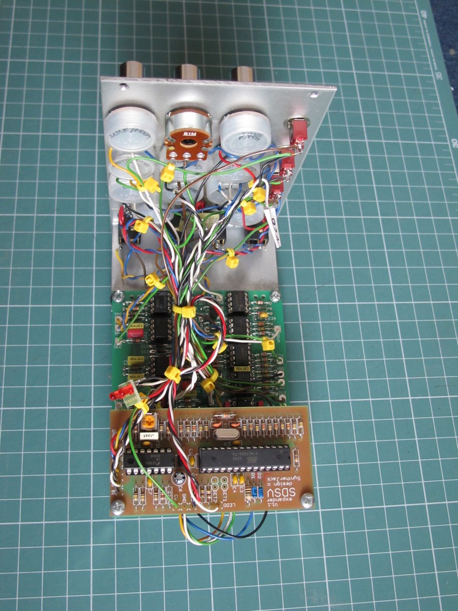
After final tests, I moved to self-etched, then profesionally made PCB. The trimmer sets the HP filter cutoff, but can be also placed on front panel. PCB is 45 x 100 mm. Some companies don’t put TOP soldermask for one-sided PCBs, thus the ugly brown color :/
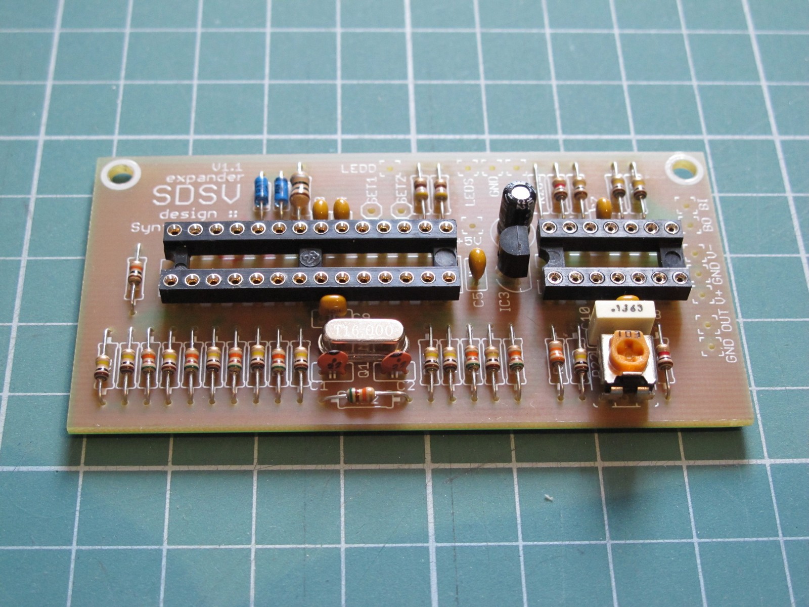
The digital expander PCB, as in orginal, is placed on the top of the analog one. Wiring is very simple – the only flaw is you have to use 3 position switch (rotary) to get all 3 waveforms – 2 original (triangle + sine-ish) and hihat. I had 2 position one mounted, so I lost sine 🙁
Finished module tests
And traditionally, a 2 years old clip from developement, so you can get some idea on hihat sound. You may also understand, why some people like to use standard hihats with electronic Simmons instead 🙂
Final specs of the SDSV hihat expander:
- based on ATMEGA8 microcontroller, all code in C (no Arduino),
- sound data – 4096, 8-bit samples (like in original) stored in uC FLASH memory,
- control voltage (0-5 V) can change playback speed from 2 to 100 kHz,
- CV is sampled with internal 10 bit ADC @ 4 kHz,
- 2 LEDs – playback speed and “default 25 kHz” speed,
- hipass output filter to roll off all unnecessary frequencies with cutoff control,
- CV input protected from overvoltage,
- CV range 0 – 5 or 0-10 V,
- can be used as standalone noise source,
- power supply – +/- 12 V or 15 V.
I think, thats all. Thanks wutierson, it would be not possible without your help!
Cheers
Jack
I love the sound you’ve created here– it’s very fresh. Ironically, the sound seems reminiscent of typical ‘analog’ Roland/Korg hats/cymbals, but a fresh version of that well used sound. It’s really cool; I plan to build some of your DIY designs, but you should turn this into a commercial module.
How would you get open/closed hat sounds with this arrangement (or how would the original SDSV cymbal/hat module accomplish it)?
Hello,
I think about it every day, not I fight with FCC/EMC regulations 🙂
Cymbal/HiHat circuits used additional passive HP filter – I don’t know exact cutoffs for both, but they could different. Both circuit could also use different part values for envelope generators, to keep HH sound shorter. I just guess.
Cheers!
Is this available to Buy
Very nice job, I would like to order some SDSV pcb with this great Hihat/cymbal module if you still have for sale.
Other question about this little Hihat pcb, can it be used with an original SDSV tom cards?
Greeting from France
Cyril