Not everybody needs an 808
Some time ago i started a DIY handclap project. The design was not based on Roland TR808, but Boss HC-2 (or Amdek HCK-100, if you like). With some problems I completed the prototype and made an eurorack module – it works really well.
The circuit
Boss circuit is different from Rolands. It uses CMOS based digital noise source (only 2 states at output – 0V or ~4,5V), which gives possibilities for some modification. As opposed to 808, this device has more sound sculpting options, more then just “level” control – 4 knobs in total to tweak and lick. I’ve tried many mods, but only 3 last as “fun and usable”. For such a simple sound, PCB is quite complex. The final schematics HQ pdf used in this project can be found here. The topolgy of the circuit is very simple – one digital noise generator (CMOS ICs based), one EG (generates burst of pulses) and one VCA (BA6110 based).
Prototyping & euroracking
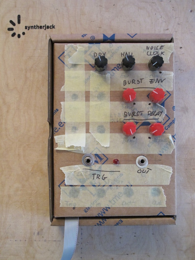
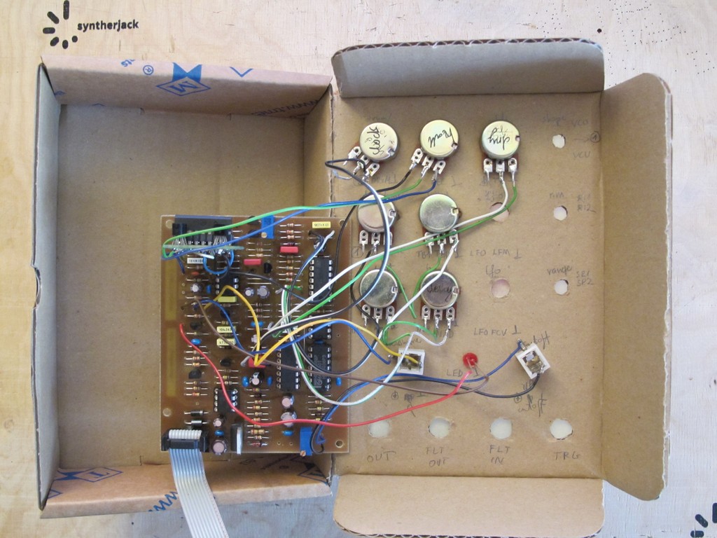
First, I prototyped the circuit on self-etched PCB (I don’t like to make complex analog projects on breadboards) in a beautiful cartoon box, leftover from SDSV drum synth project. I made an small error in BA6110 connection, so I had to put an additinal small PCB with transistor converter (original circuit uses BA622, I have forgotten about it).
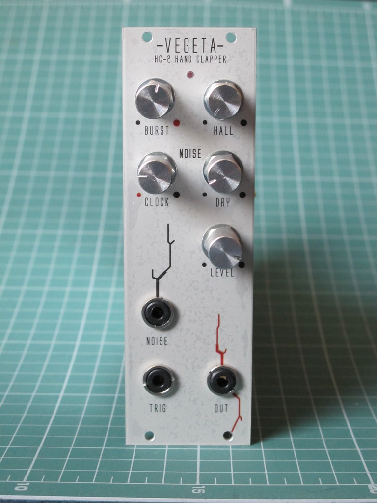
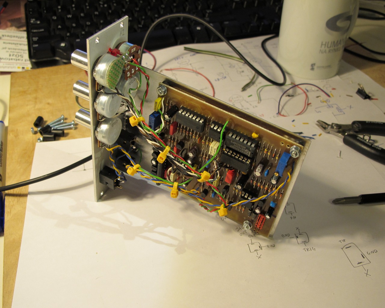
After tests, I moved to final , professionally manufactured PCB (I made only one small error in prototype) and put in into 8HP eurorack module. The front panel doesn’t look as good as it should – I used acetone for aluminum cleaning, which caused the water decal to peel off. Now I use simple soap, works so much better. The full description of the water decal method can be found here.
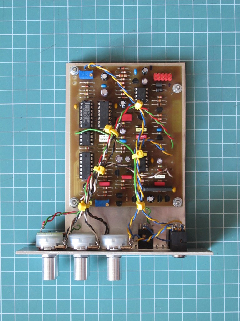
The trigger indication LED PCB (the small green one) is mounted in somehow silly way – sticked with a two-sided adhesive tape to a back of the pot. But you can still remove it without problem, in opposite to hot gluing *.
*it was a bad idea, has fallen in 2 years, had to glue it anyway :/ (added 8.03.2018)
The front panel is simple and every knob makes a difference to a sound. All pots are Alpha Taiwan 16mm with dust cover – very cost effective in synth DIY and much better then no-name asian devices. The CLOCK control is my favourite one – can make the clap sound really FAT!
Full data
Controls:
- HALL (“fake reverb” level),
- DRY (noise source output filter cutoff),
- BURST (pulses count in envelope),
- CLOCK (noise source clock speed),
- LEVEL (output level).
Inputs / outputs:
- TRIGGER (trigger pulse input),
- OUTPUT (handclap output),
- NOISE (noise output),
- LED (indicates trigger).
Mechanical:
- PCB size: 80×100 mm,
- module front panel size – 8HP (~41×129 mm).
Power consumption – maximum (only positive rail) :
- 0 mA @ -12V, 20mA @ +12V,
- 0 mA @ -15V, 15mA @ +15V.
And now, all you are waiting for, a demo! (I find handclap demos very boring by definition, but this one crossed the limits ).
A more complex approach to handclap synthesis was used in my SnapClap project, check it out!
Cheers
Jack
The ‘here’-link to your schematics seems inactive. Would be nice to see you fixing that. : )
Cheers from Germany! Nice blog : )
Thanks for the info, link fixed!
Great projects, any chance of sharing the pcb mask?
Keep up the good work.
Thanks
I second the pcb layout, that would be ?
Hello,
Great clap! Unfortunately I couldn’t find any PCB conductor tracks for etching, what a shame!
Every once in a while it makes a kind of bark or squeak sound. You can hear it the most at 2:04-2:06 in the video.
What’s that all about!?
How is the PCB assembly attached to the front panel? I do not see any screws.
Cheers
Ian