
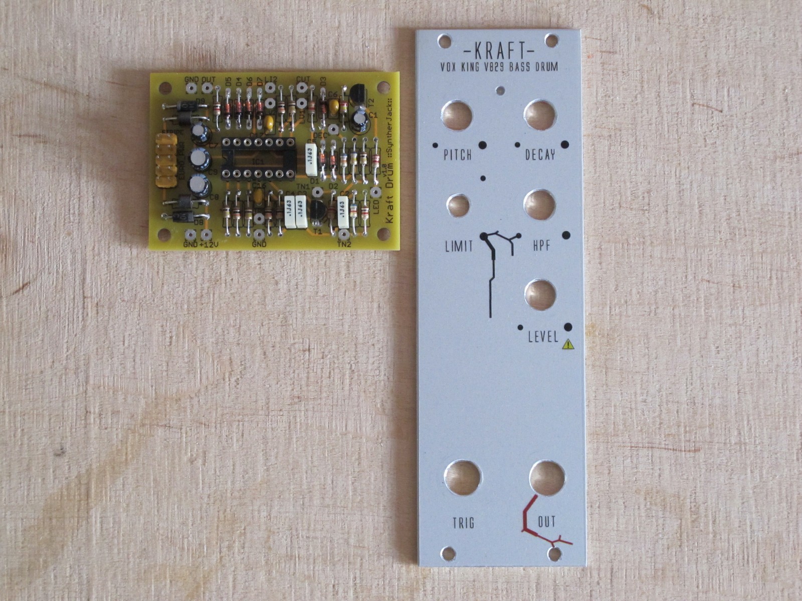
This is a third part of my eurorack DIY tutorial. Previously I wrote about front panel mechanical work and waterslide decal applying. Now the PCB and front panel need to be connected together. Custom PCB holder is a must if potentiometer and jacks are not included in PCB design. Lets get to work!
The ideas
I want PCB holder to be fixed with potentiometer or jack nut, this way panel look very tidy. I don’t like random screws flying around. So, lets test some eventual placements of holder:
- (Idea nulla) PCB parallel to front panel – this won’t work, PCB is wider then aluminum front panel; I should have though about it earlier – only few milimeters are missing :/ (grinding is not an option),
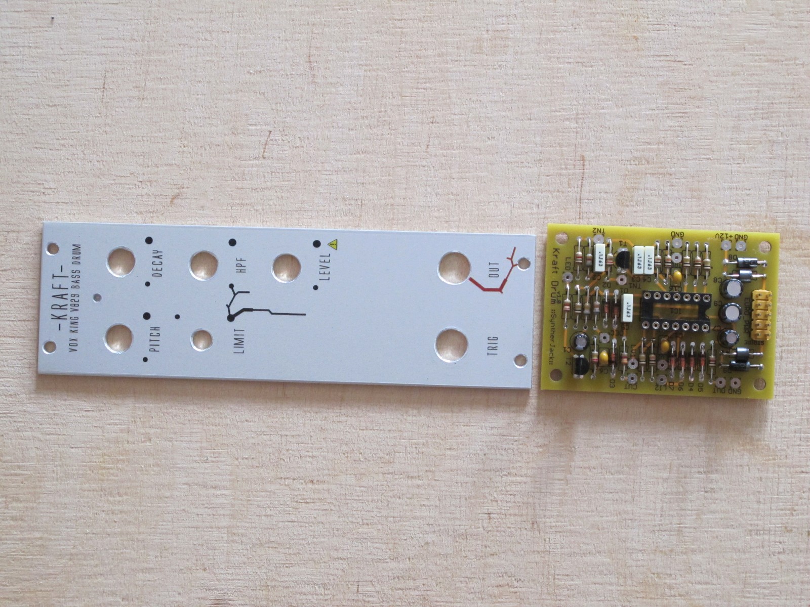
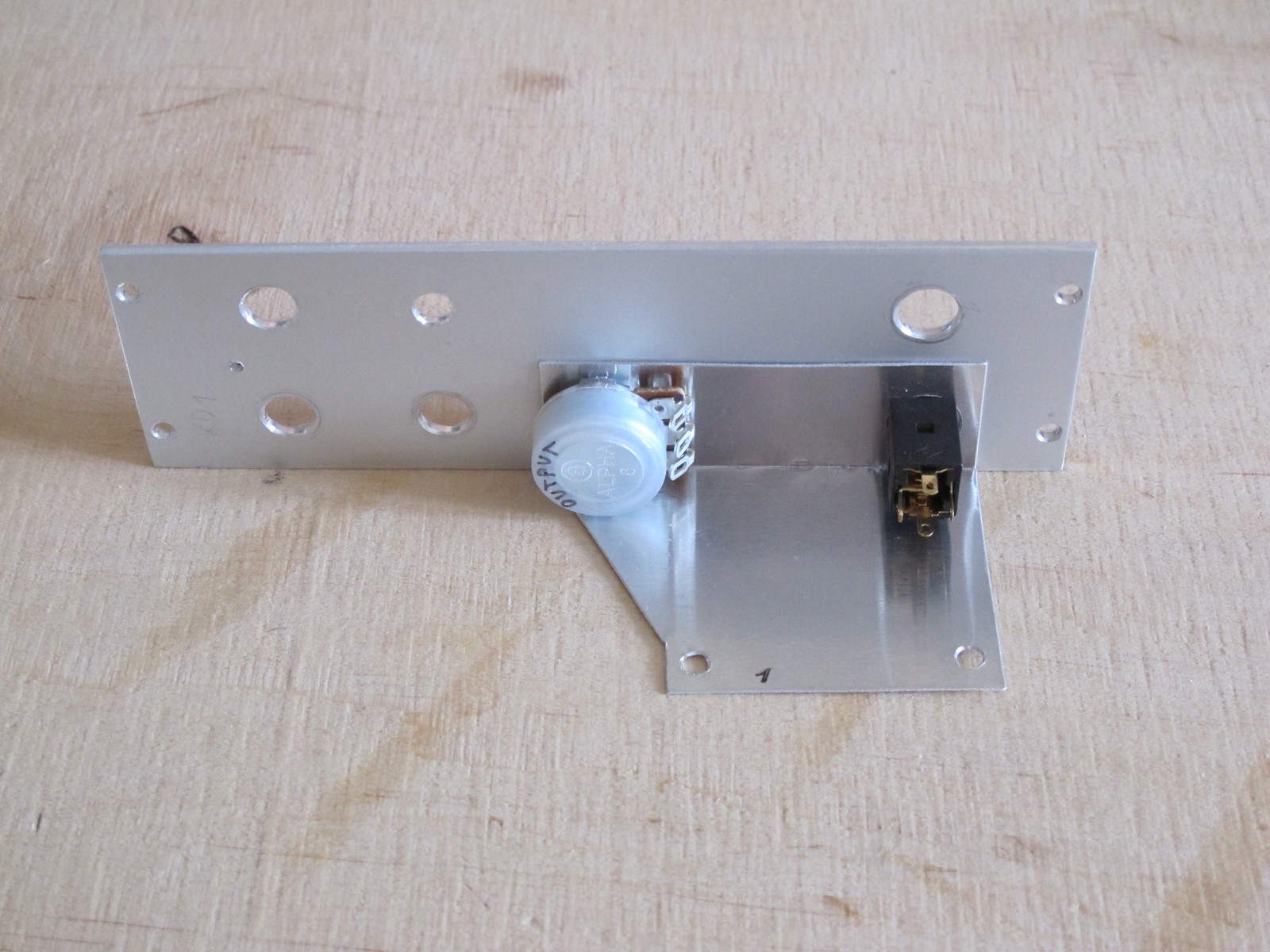
- (Idea I) PCB placed perpendicular to front panel and holded with OUT jack nut and LEVEL potentiometer nut; quite ok, but power connector on the top is not a good idea (also not bad, but could be better),
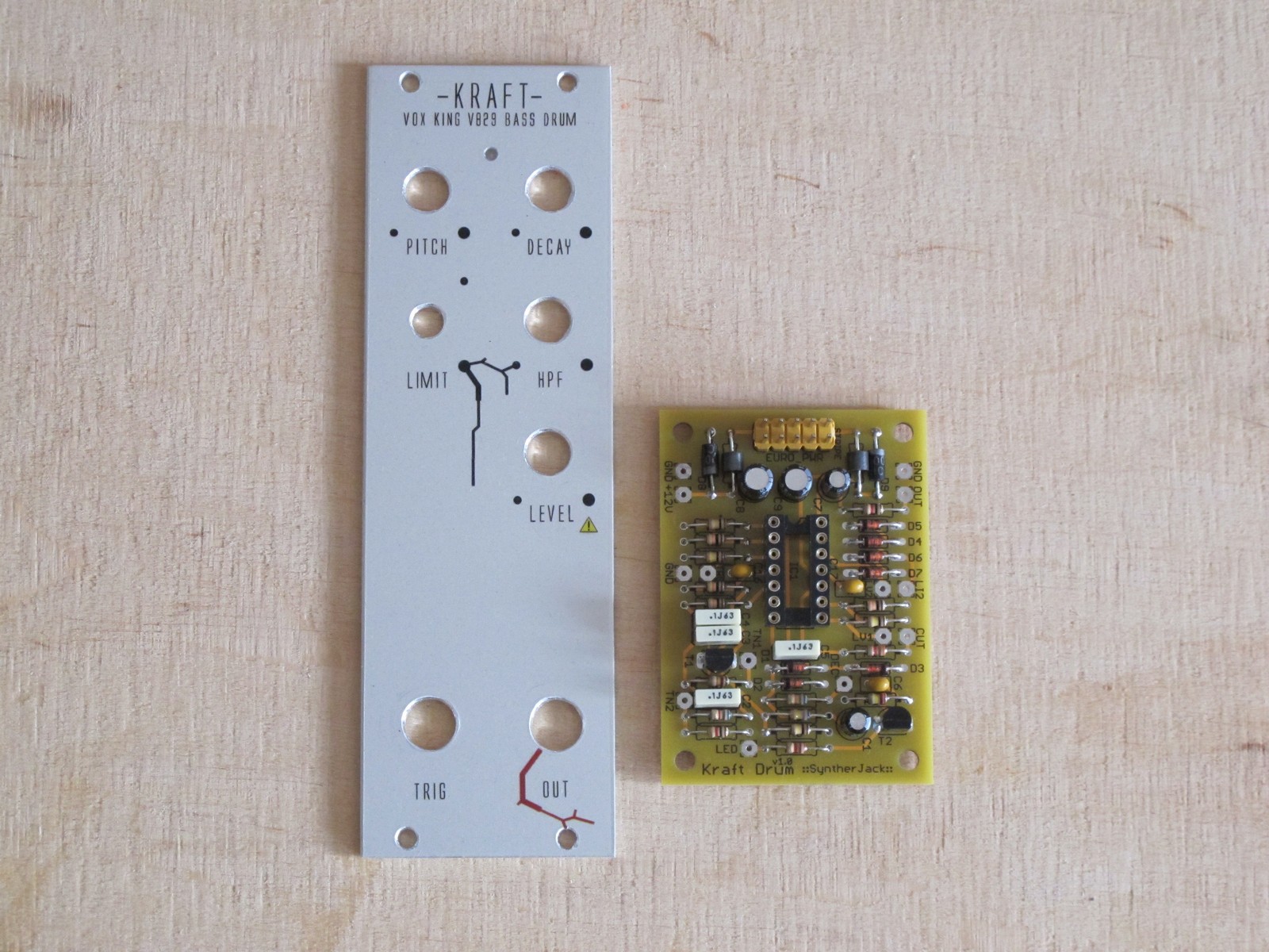
- (Idea II) PCB holded by OUT and LEVEL as previous – I’m not shure why I dumped this idea, it was quite good actually; wiring should be easy, power connector in right direction…
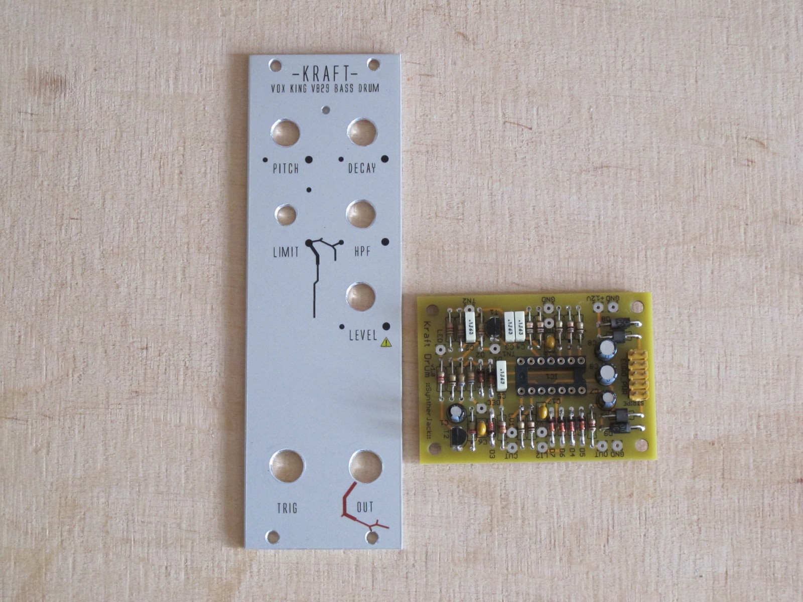
- (Idea III) PCB perpendicular to front panel and holded with HPF potentiometer nut and LEVEL potentiometer nut; not bad, but it would be hard to wire HPF potentiometer, also I don’t like when PCB is mounted too high in relation to panel, it messes with my modulars feng shui (and the module will not stand alone, which is handy for wiring),
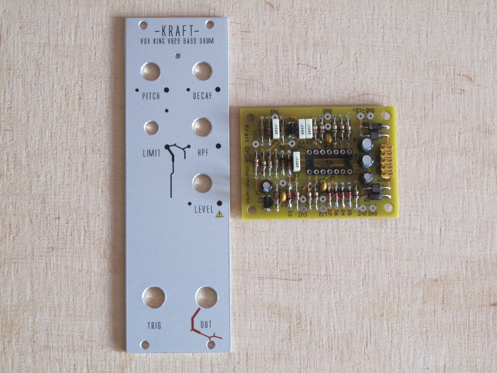
- (Idea IV) top left and top right placements – bad for previosly mentioned reasons, difficult wiring.
I decided to go for idea I, where PCB is on the bottom with power connector facing up.
The other thing is how the PCB will be fixed to the holder. There are not many options – PCB can be attached using:
- 2 screws – gives you an easy access to PCB solder side, great for modding and prototypes, simple to make and cost efficient,
- 4 screws – good PCB support, sturdy.
Back in the day I made PCB fixing with 4 screws, but 2 are sufficient enough. There is not a lot of stress on the PCB while hidden deeply in eurorack case anyway.
Measuring and cutting
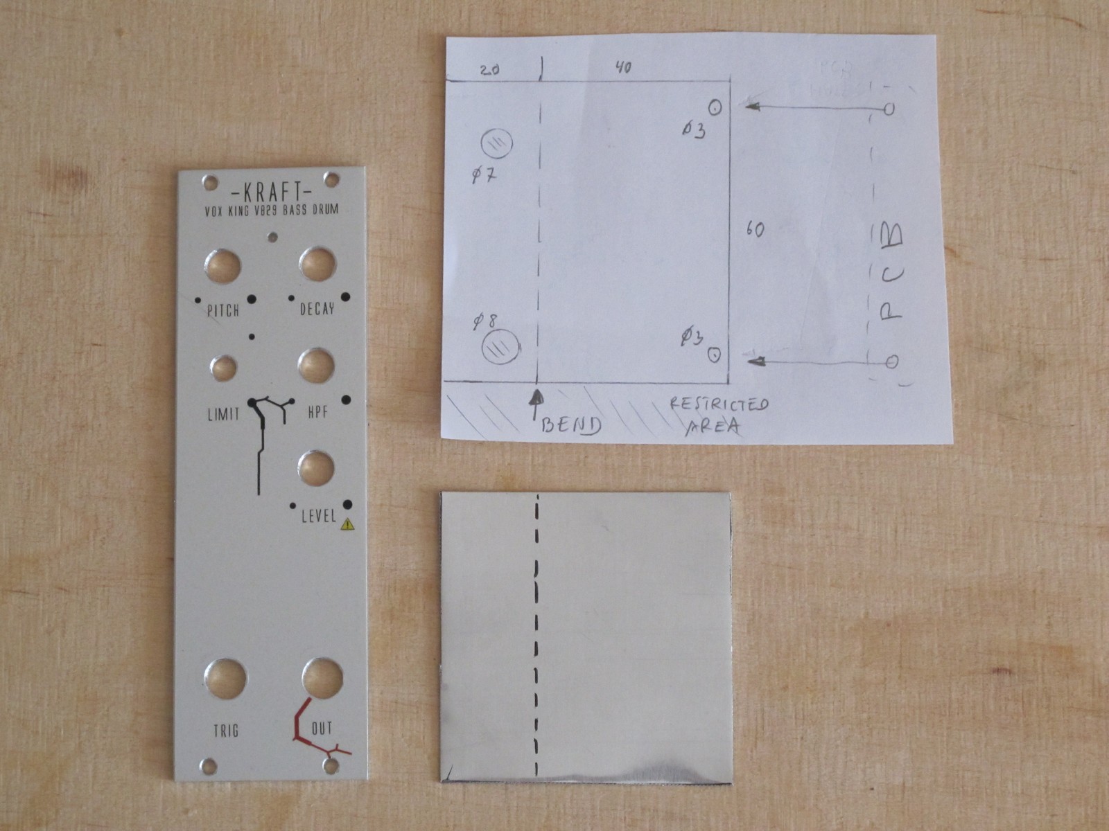
The first thing to do is check all dimensions and plan how the holder should look like. It is also important to take into account the size of the metal sheet you have – mine is very long and 120 mm wide (and I was planning to make 2 modules), so 60 mm dimention was a dream 🙂 Notice the “restricted area” on the paper plan below, it is about 10 mm from the top and bottom of the panel – thats where the eurorack mounting rails are.
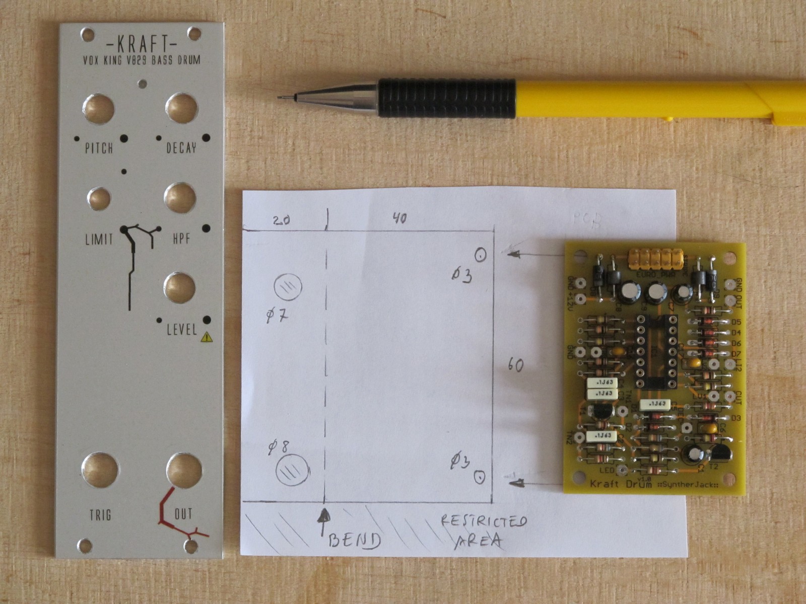
Looks not too bad – we need 60 x 60 mm aluminum sheet piece with just 4 holes, bended. Simple. I use 0,5 mm aluminum sheet bought in hardware store – light to cut, bend, drill and cheap. First thing is to mark cut lines, you can wash the marker away with acetone.
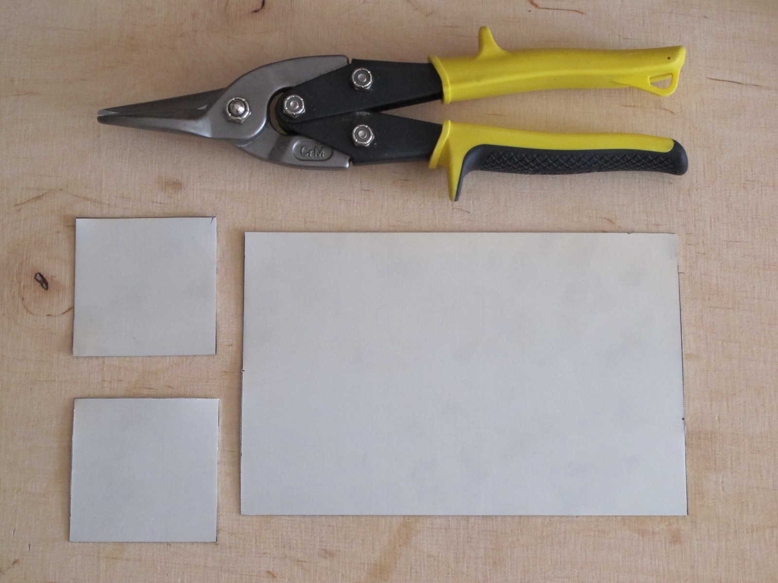
Straight cuts are easy with good sheet metal sheers – I use one from Stanley, they work like charm (and cost around 15 euro). I read somewhere, the good test of such sheers quality is how they cut very thin paper – if they cut fine like the sharp paper scissors, the quality is high.
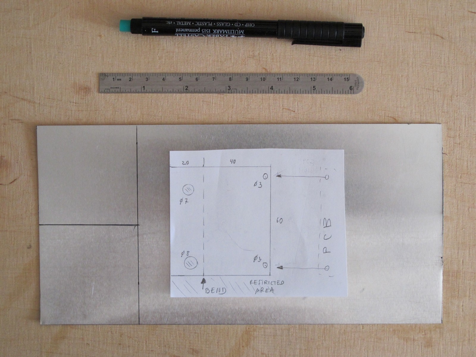
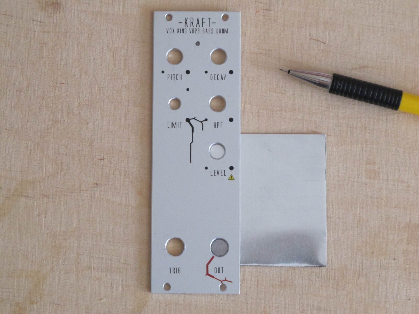
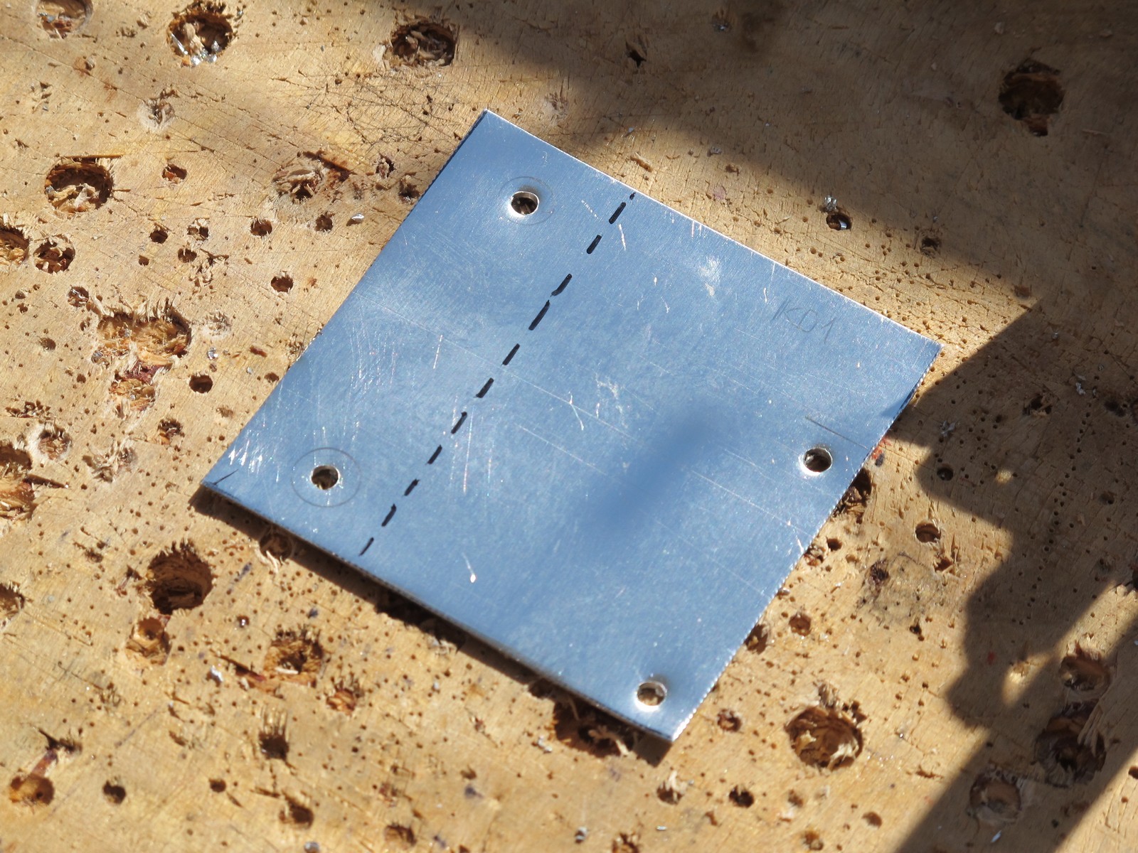
First draw the bend line, about 20 mm from side, as planned.
Slip the cutted piece under the panel, the bend line should not be visible (we want whole PCB holder to be hidden behind). Now to mark the holes positions. They must be drilled perfectly as they should align with the ones in front panel.
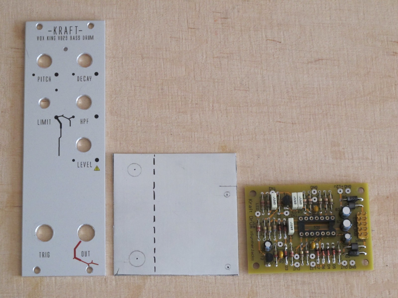
I decided, the idea II was really good. The PCB will be mounted like this (photo below). Fortunately all dimentions stay the same, only the PCB fixing holes must change its position.
Drilling
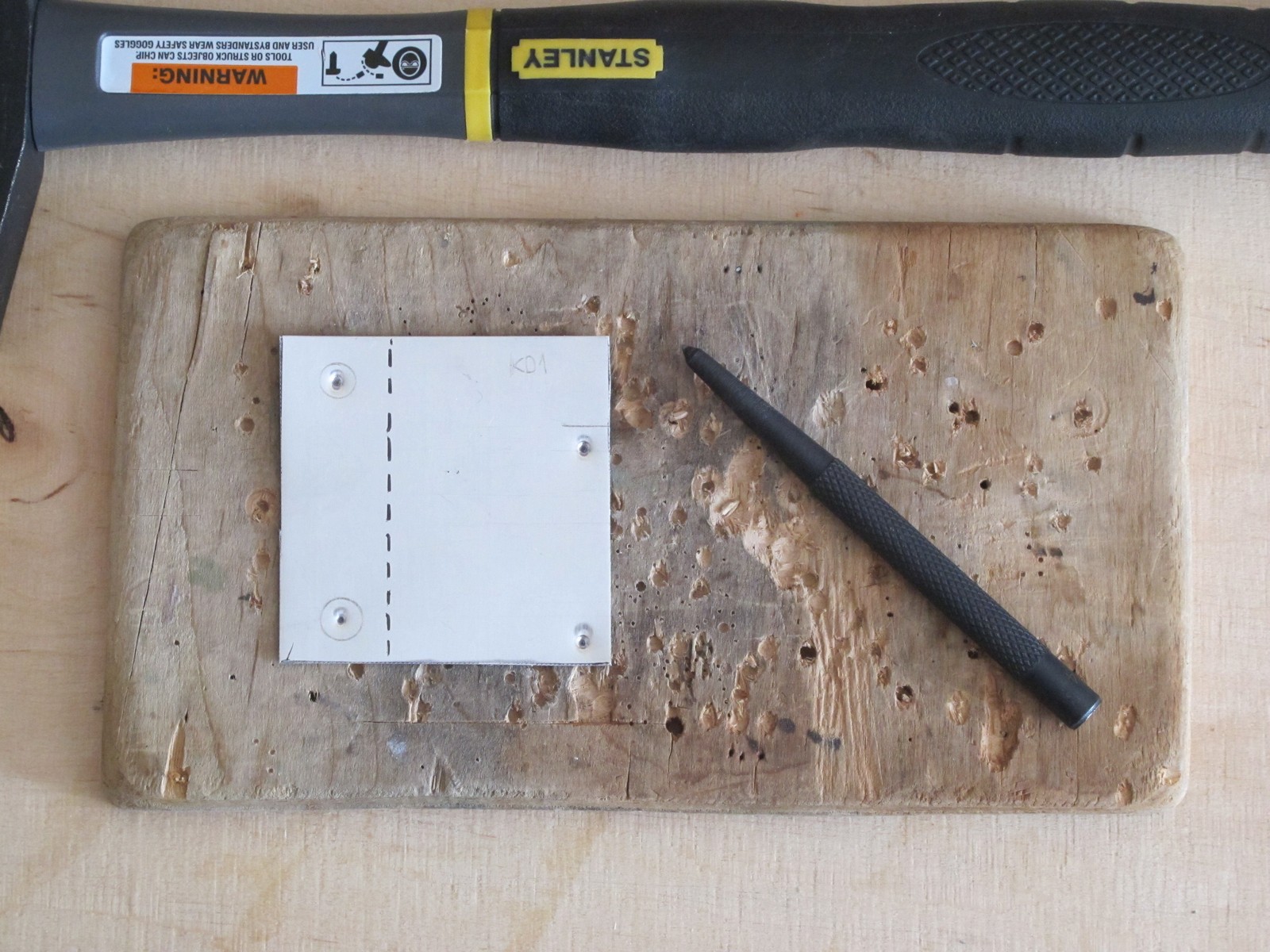
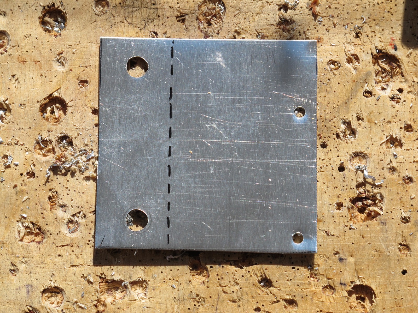
Now take the pointer, hammer and hit gently. The sheet is very soft. Don’t care about sharp edges or if sheet is not, you will make it look amazing at the end.
I don’t like to drill in thin metal sheet. Small holes are simple to make, but anything over 5 mm is a pain. So, start with a 3 mm drill (the target diameter for PCB mounting holes).
Then ream pot / jack holes up to 5 mm with drill – 5 mm hole is big enough to use a hand reamer, very useful tool (and hard to get where I live).
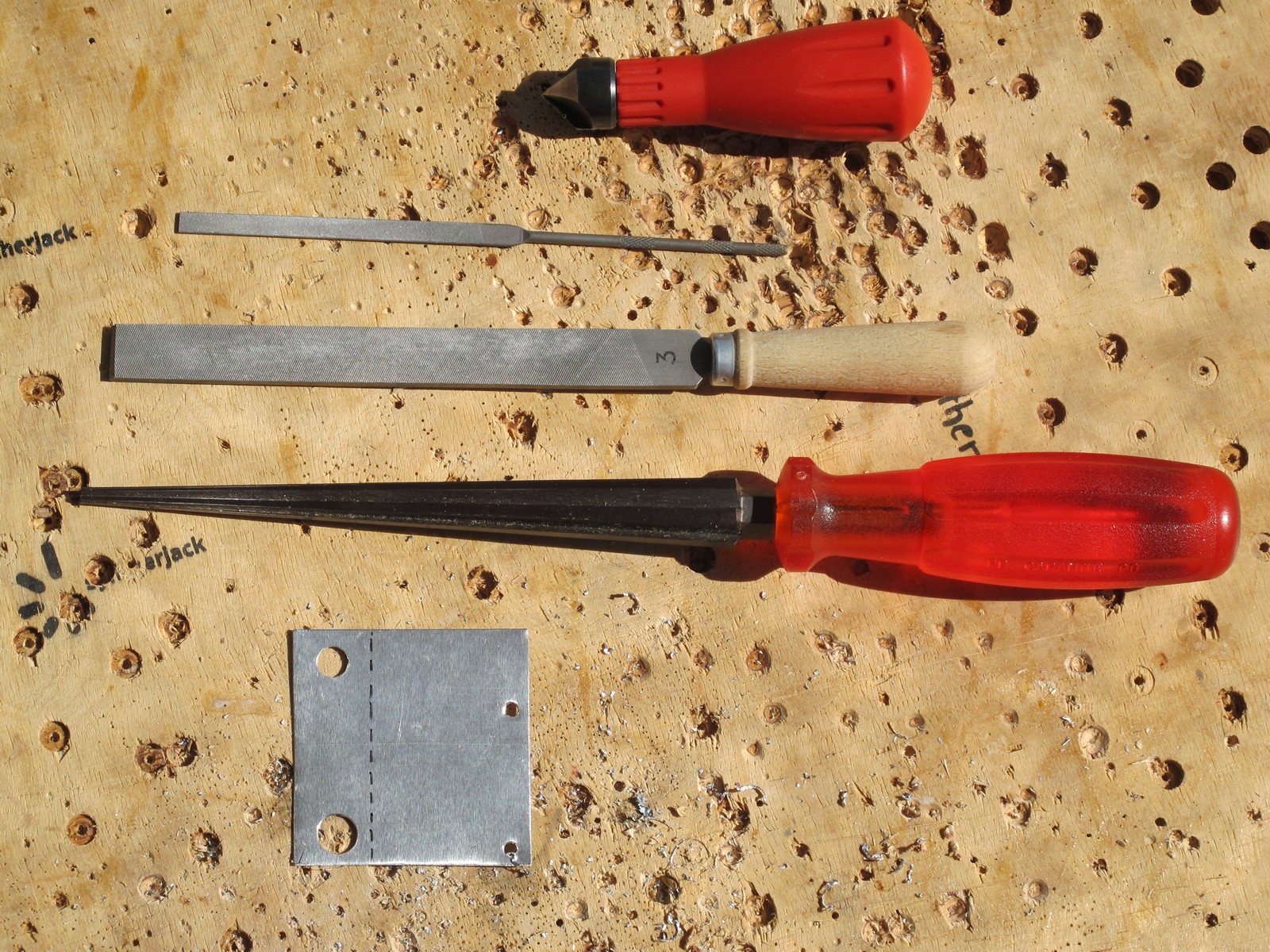
The best method I found to make large holes in sheet is using hand reamer (longest tool on the photo below). This particular one is made by Swiss Tools (~35 euro). Other tools I used are: 2 sharp files and hole deburring tool by Wolfcraft (~8 euro).
Just put a reamer into hole and twist few times. Get the pot and jack to check if they fit. If the holes diameter is too big, it is not bad – it gives you some space for fine adjustments of the PCB position behind the panel.
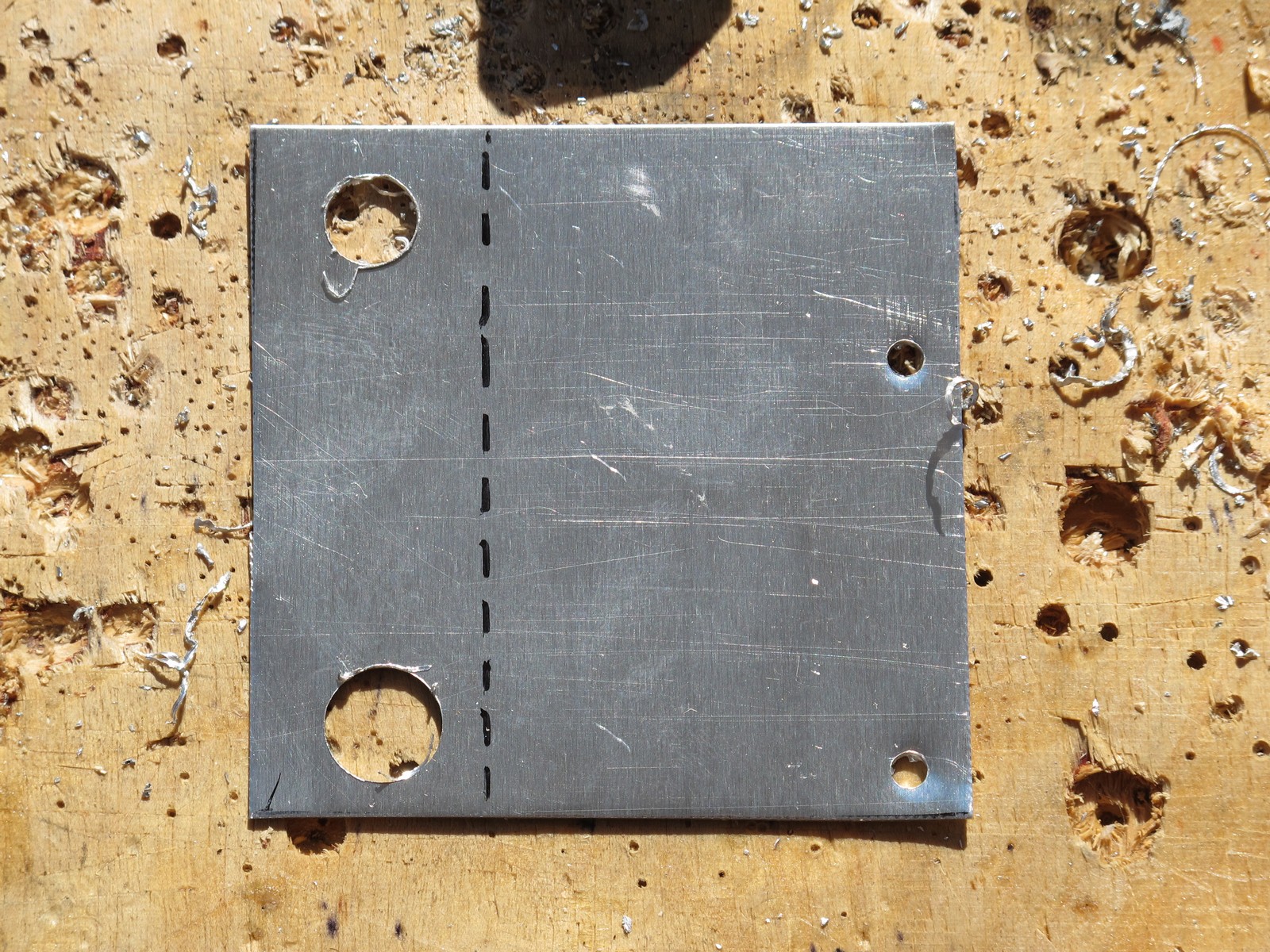
Take the deburring tool to even the hole edges. Few twists from both sides will do the job. Our sheet is ready to bend.
Bending
For bending you can use an edge of the desk and fingers (sheet is really soft) or a special sheet metal bending and folding straight seaming pliers (~20 euro) – what a nice name 🙂 Tool itself is very handy and useful for other jobs like f.e. sheet flattening. The quality of mine is very shitty and the lock has broken – thats why i’m using a rubber band.
I also draw a cut line I forgotten about and used metal sheet sheers to remove an additional material. The holder is ready and shiny!
Fixing PCB holder
Now lets fix it to front panel using potentiometer and jack nuts. For jack I use my special DIY tool and big wrench for potentiometers. And if you are curious, the water decal is barely scratched!
Looks exactly as I imagined. You can rotate potentiometers to make wiring even more pleasant.
Thats it, the PCB holder is ready. That was easy and satisfying. The last step is to mount the PCB, wire and test the module.
Cheers
Jack
Can’t believe how useful your posts are! Exactly what I’ve been looking for!!
Just one question I’ve been struggling with: What’s a good distance between knobs? Ideally I would like having 2cm between each knob, but if I plan to do that with an ADSR Envelope, then won’t be possible. Maybe 1cm gap between knobs is ok? What’s your experience?
Thanks a lot!!
Hello, usually I try to keep a distance of 20 mm between center of thr knobs (10 mm diameter or less). So, 10 mm between edges of knobs should be ok. Envelope is not often use as “hot live-act” feature, so small distance should work. For often used knobs (like cutoff) i prefer more then 10 mm if possible. Btw. (if you want to go deeper, I’ve got an amazing book form the ’70, with a chapter about knobs style and distance between depending on operation type (one hand/two hands), time of reaching the knob etc; real hardcore stuff) Cheers!
Can you name the book ?
It is in polish. “Poradnik konstruktora sprzętu elektronicznego”, Wydawnictwa Komunikacji i Łączności, 1981 (so, very late 70s). Maybe I should write a short article about knob placement in the future…
Dear Mr. Jack,
On 31st January 2019 you commented about the problems of control knob placement.
The problem is called “ergonomics” – you probably knew that – and it’s about the best way of designing equipment so it can be easily used by people.
I think your idea of writing a short article about control knob positioning on synthesisers is excellent. Stay in touch.
Cheers,
Dave