Lets go to the last part of our eurorack DIY. The PCB is designed and tested, front panel with decal and PCB holder made. The last thing is to electrically connect PCB with all panel mounted devices. There is a lot of place for mistakes, so I recommend to work slowly and stick to the schematics (or wiring plans).
Before the wiring…
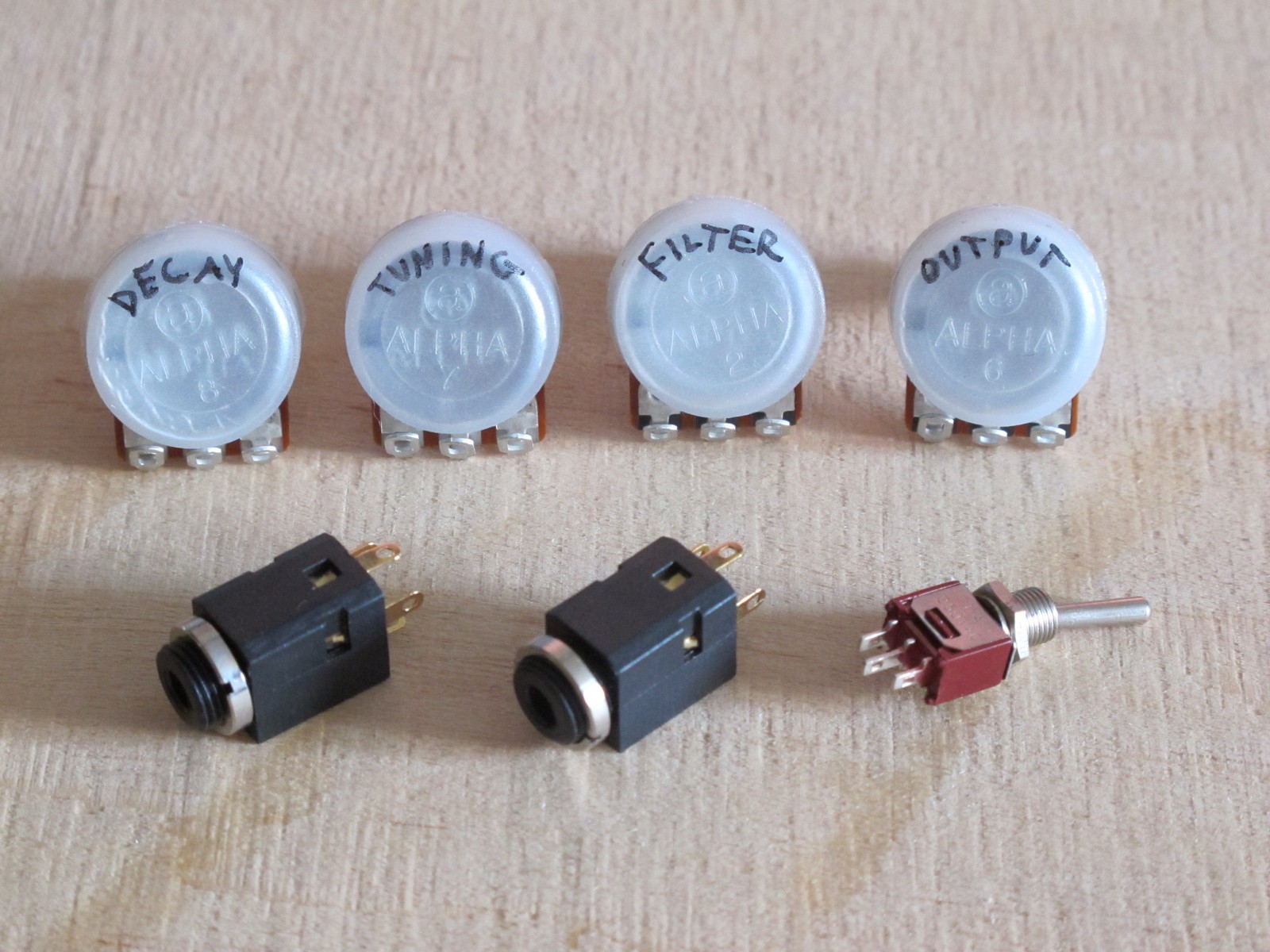
… get all panel mounted devices, check its values and mark their function. There is nothing worst then launching your vanilla module and thinking: “The resonance pot works strange. Do I really used 50k reverse log?”. This way you have one problem less.
Put the PCB to the mounted PCB holder and check the approximate distance between farthest panel element and PCB wire pad, then add 50 mm. For front panel wiring I usually use 200 – 250 mm wires and then cut / strip them if necessary.
To avoid errors (and speed up debugging) I use simple rules:
- blue wire is always GND,
- red wire is always +V; (-V is not very common on the front panel and I don’t want to waste a specific color),
- yellow wire is input or output signal, i.e. all audio and CVs connected to jacks,
- grouped connections (f.e. to one, 3 terminal potentiometer) must use clearly different colors, f.e. black, white, green (not many colors left) – this way you can track them easly, as the common mistake includes switching center and side terminal.
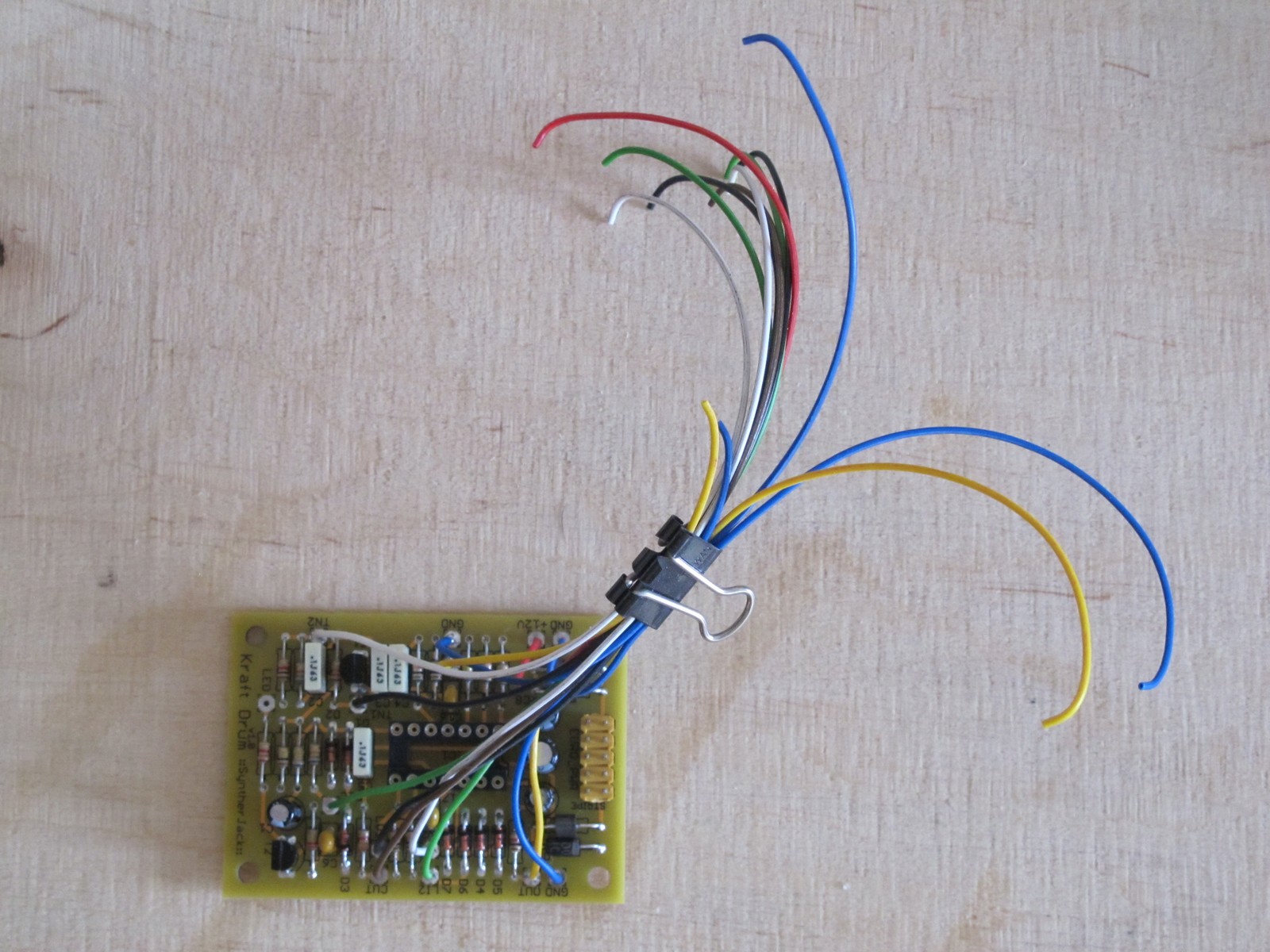
To keep wires tidy while front panel wiring, I simply use office paper clip and take only the wire I need.
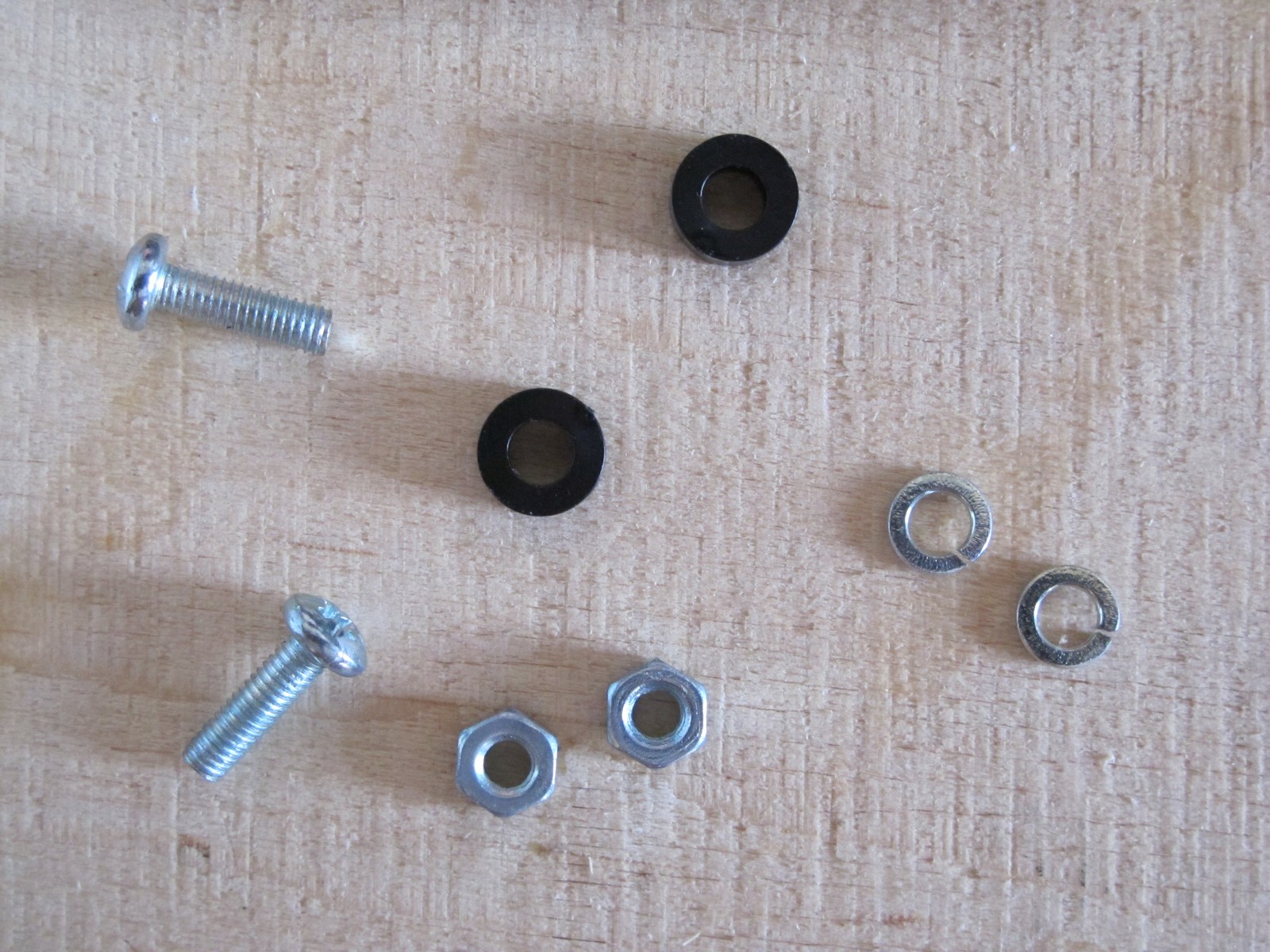
Printed circuit board to holder fixing pack – 10 mm screws, nuts, spring washers (plain will work too) and 2 mm plastic spacers (to ensure the PCB solder side will do not touch the conducting aluminum sheet).
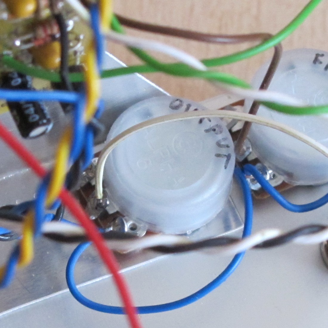
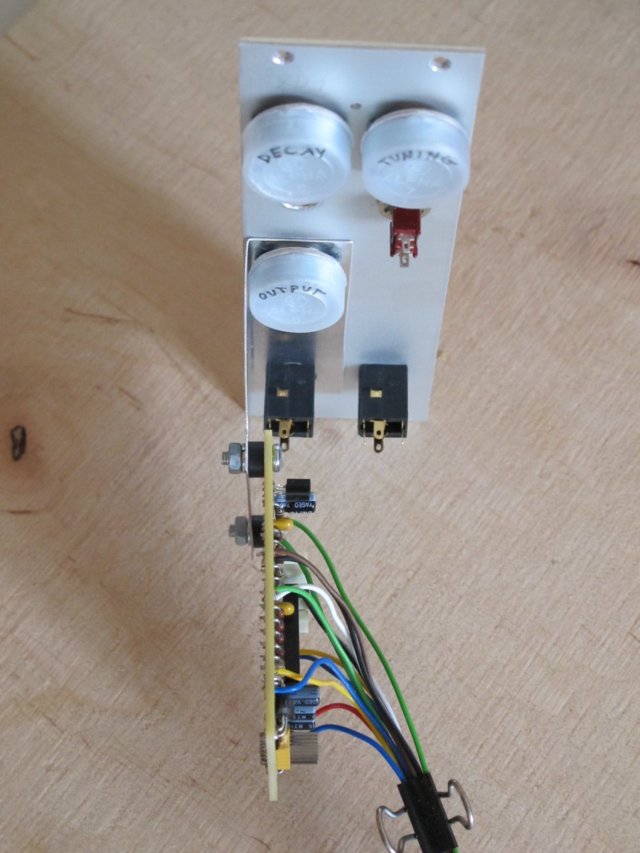
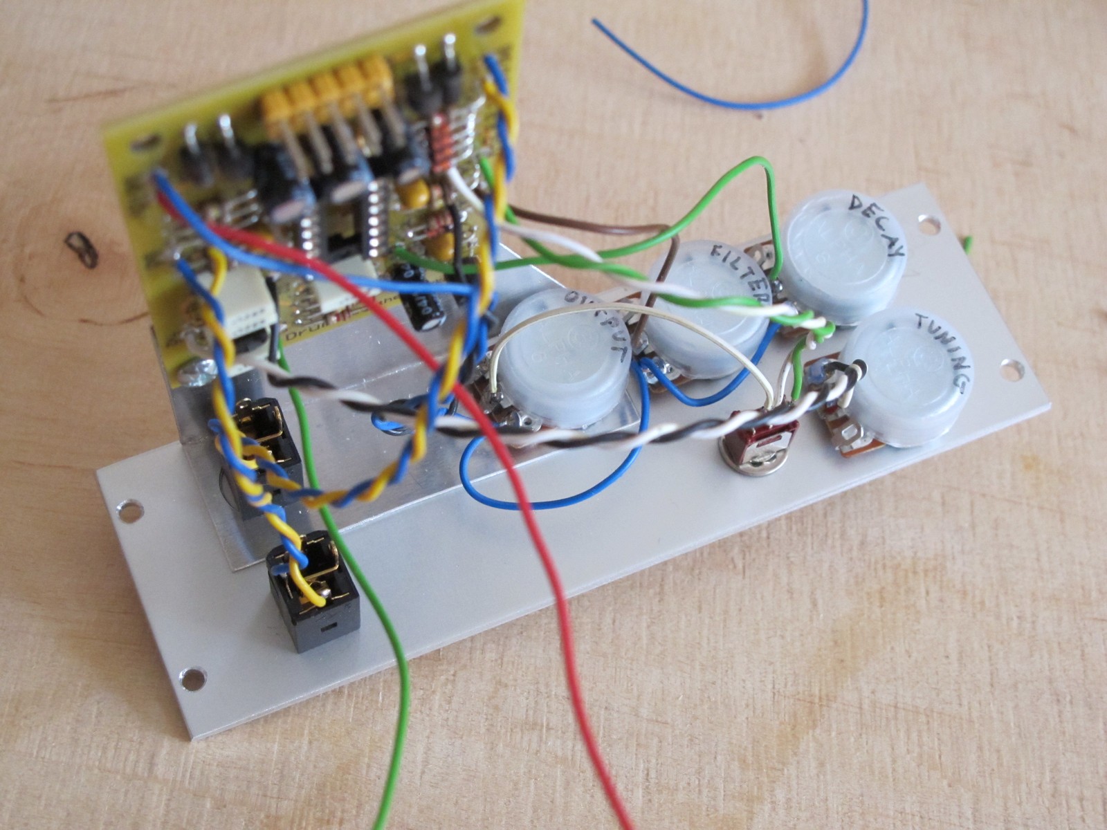
Now we need to put everything together. Unfortunately all pots are 17 mm in diameter (16 mm + 1 mm of anti-dust plastic cover) and there is really tight. To be able to solder DECAY pot (the one on the top left), I didn’t mounted FILTER pot (it should go between DECAY and OUTPUT) to have a free way to DECAY pot terminals. This is no problem for TUNING (switch below it is small) and OUTPUT potentiometers (a lot of place below it, but can also be rotated for better access).
Wiring!
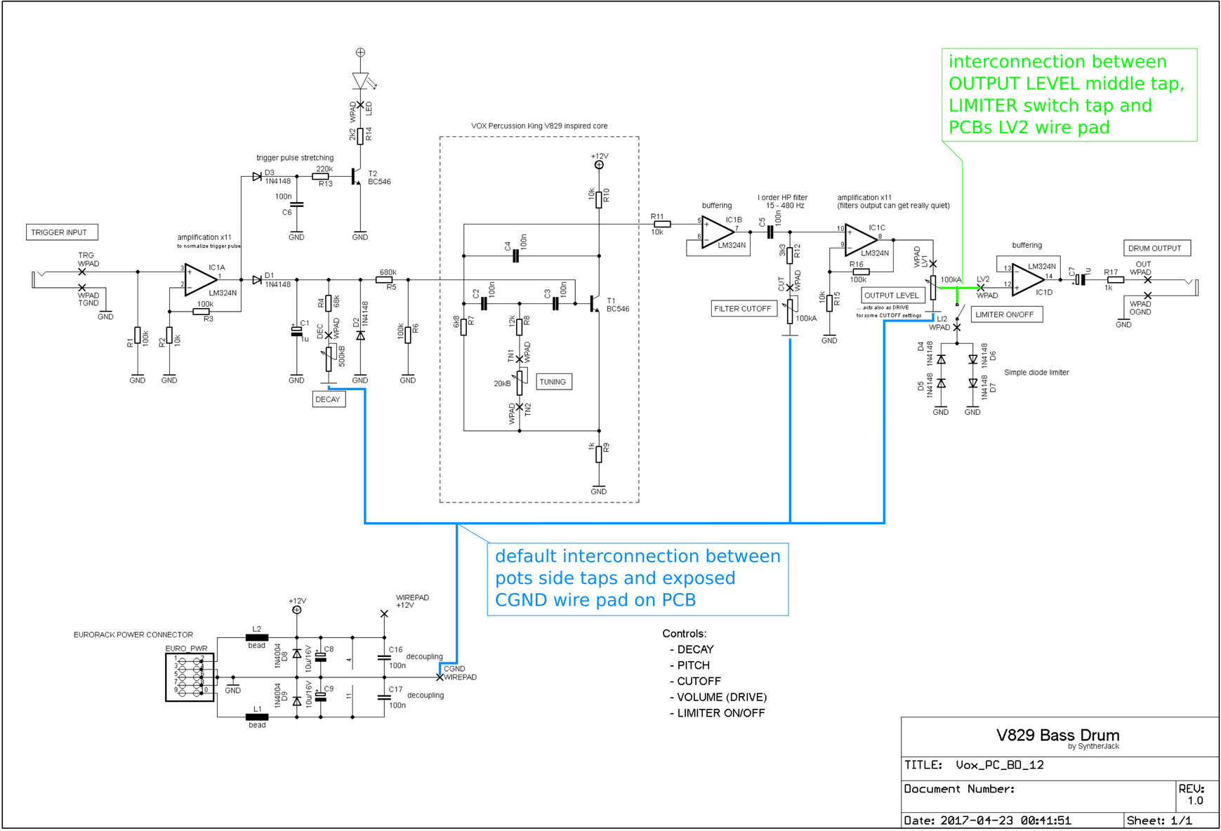
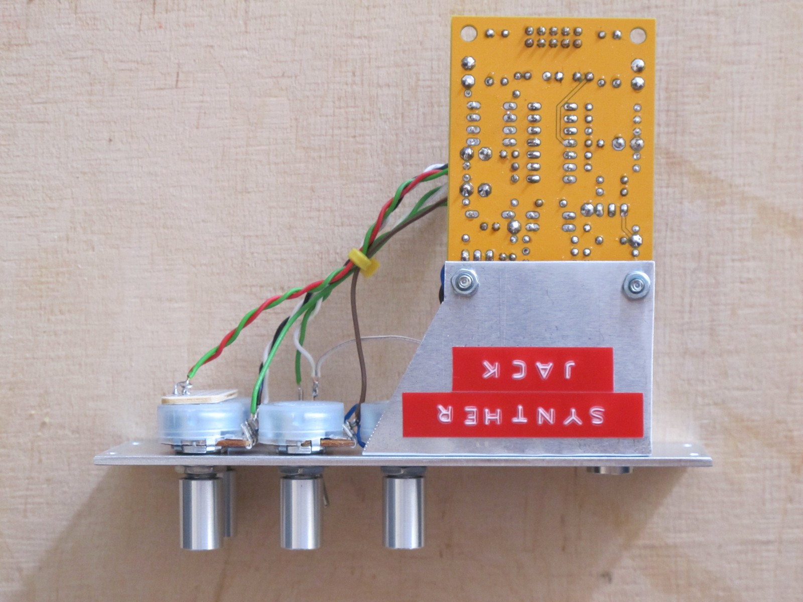
Now we are ready to wire out module! There are only 2 jacks, 4 pots and a switch – quite easy task. Also 2 interconnections on the front panel. There is no additional wiring diagram, so you need to read everything from the schematic. Because the panel mounted elements are outside the PCB, their connections are sometimes marked in a strange ways on the schematic. Generally you are looking for the connections between two front panel parts (potentiometer / jack / switch / LED) – sometimes shown in a direct way (green) or as default connection via power lines symbols (ground, V+ etc, marked on the schematics with blue).
The rest on the connections is straightforward – just some front panel mounted component terminal to PCB wire pad. I always use small jack socket description sheet I made few years ago to not switch the connections accidentally.
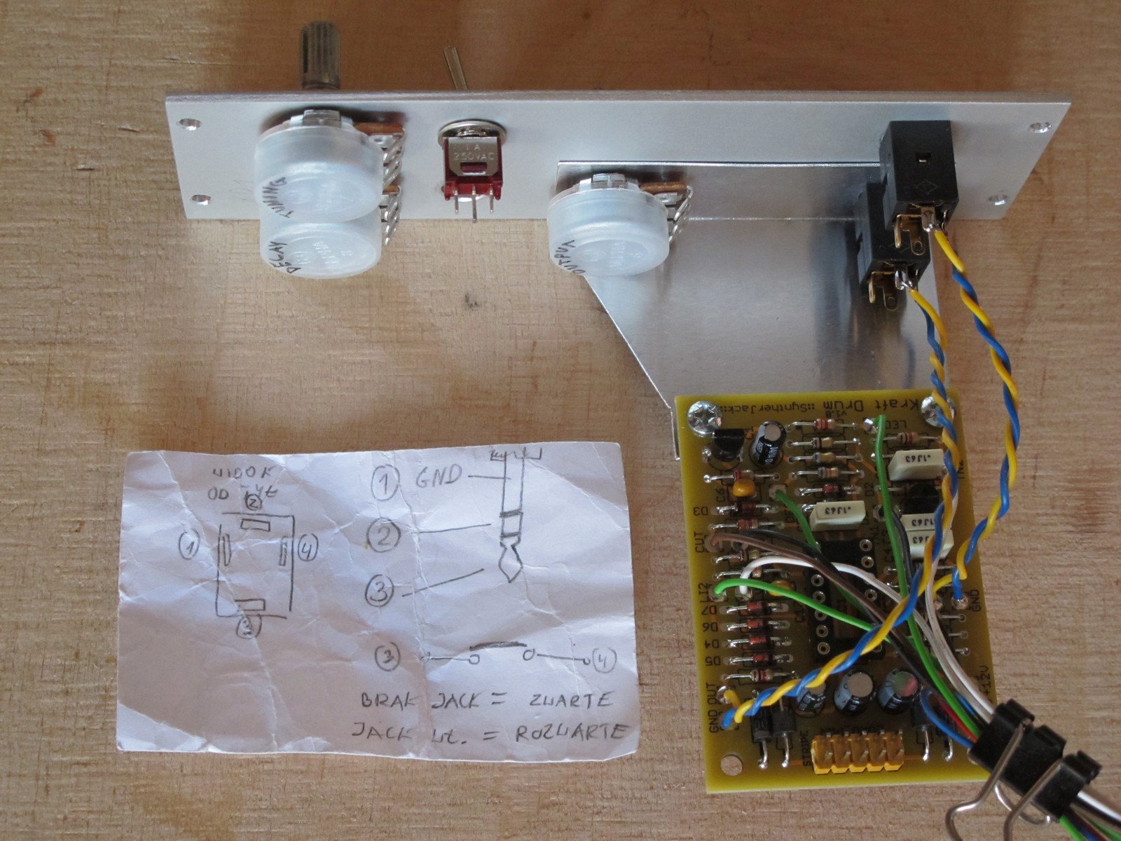
First I soldered the jacks wires, then the OUTPUT pot. Moving in one direction is handy, because there is always enough space for soldering iron. Then I soldered a green wire to DECAY pot, but noticed, there is also a blue GND that needs to go thru the FILTER pot (so I had to install it anyway). Wiring itself is almost pure improvisation 🙂
Almost there…
Trigger LED holder
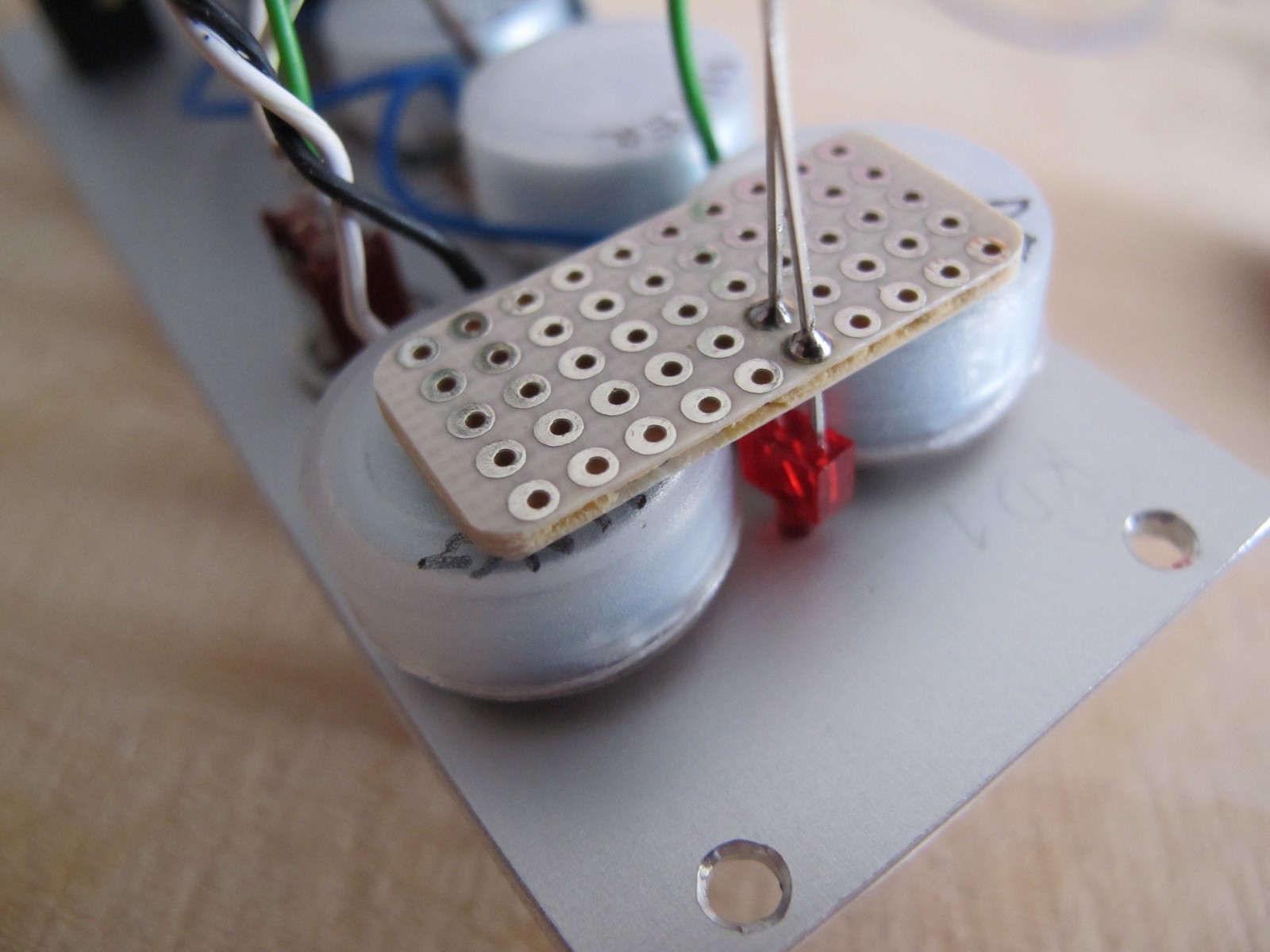
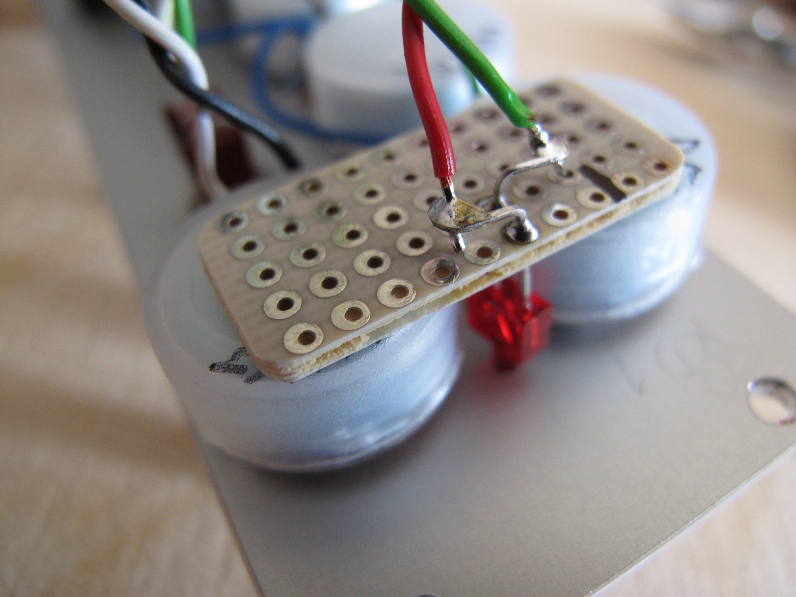
The one thing is missing – trigger LED. It is sqeezed between DECAY and TUNING potentiometer and it needs a little effort to fix it. The way I usually use is to add a small universal PCB and glue it to back of the pots with double sided sticky tape (or just hot-melt adhesive). This way you can disassemble LED later.
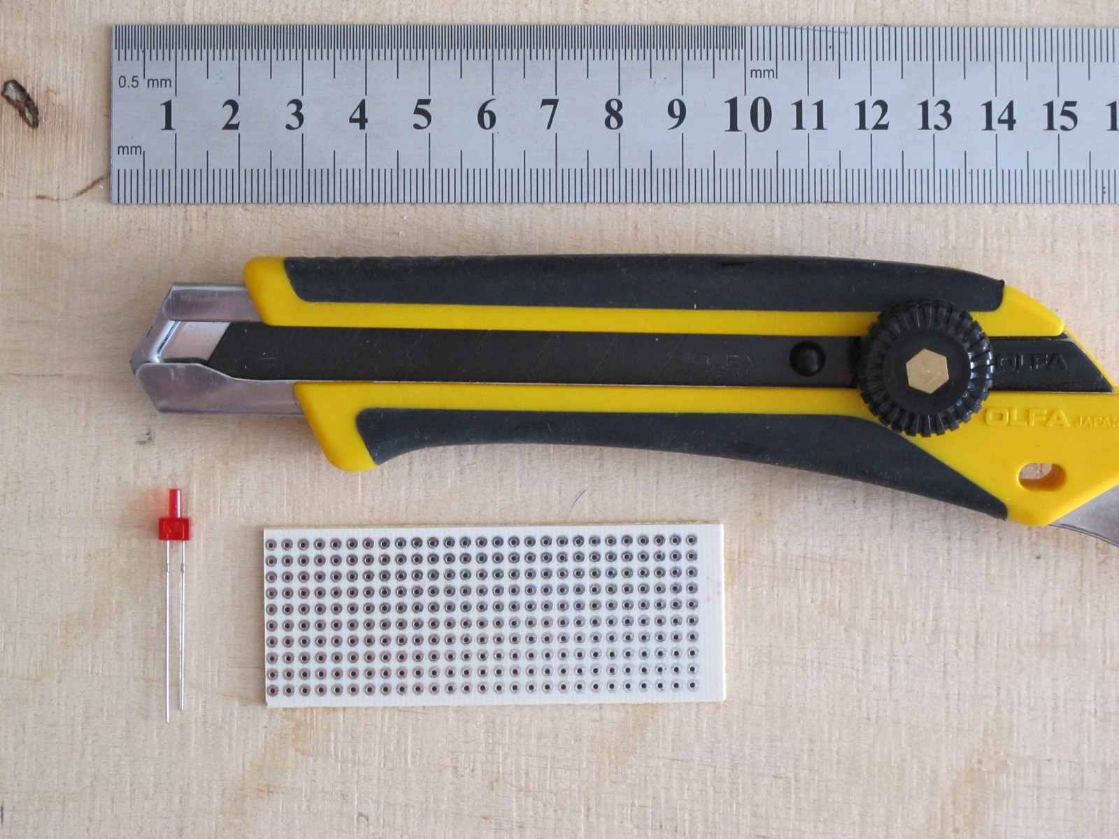
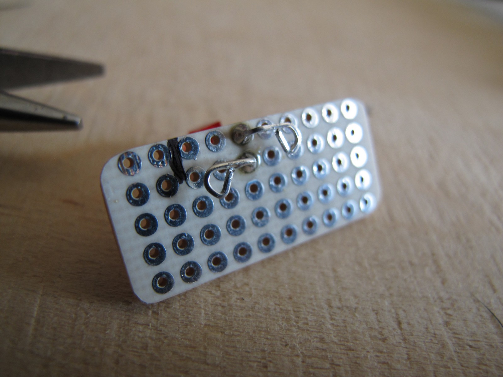
Lets prepare a LED holder with basic tools. For PCB cut I always use a sharp segment knife (Olfa L-5 (~10 euro) with Black Series blades) and a steel ruler. Just few straight cuts from both sides and you can break every PCB with ease.
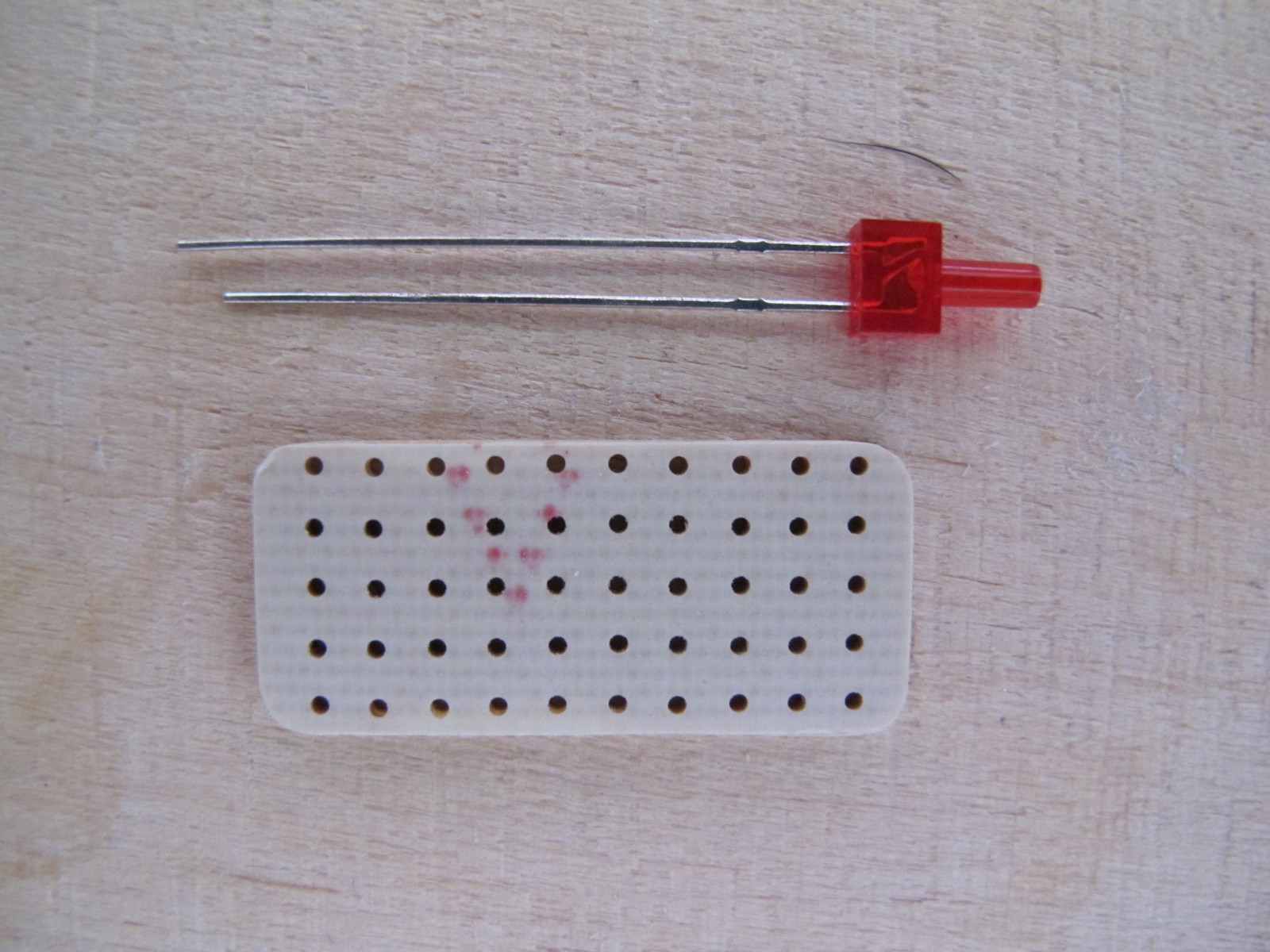
First I put the LED into the front panels hole, then slided a PCB onto it and soldered. This way the position of the LED will be perfect, but you have to be careful not to break throught waterslide decal!
Now mark the LEDs GND (usually* the shorter terminal), cut the both legs and bend them into loops – it makes wire soldering more easy.
*once had a small adventure with SMD LEDs. According to datasheet, the anode is marked with green stripe and I placed them like that. I finished with almost 40 LEDs soldered backwards 🙁 Now I check every LED I solder with a tester.
The last thing – solder the LED and glue PCB to the pots (or not, if LED holds on by itself). According to schematics, the anode goes to +V (red wire), and cathode to transistors collector via resistor.
Finishing touches
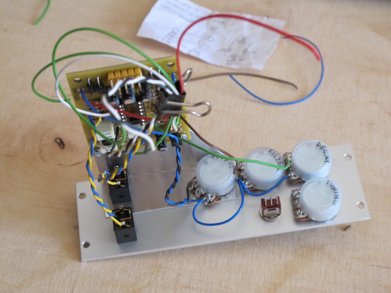
All the wires are connected. It is a good time to check them once again (I love checking things!). Look at the potentiometer teminals, maybe two of them are shorted (happens quite often).
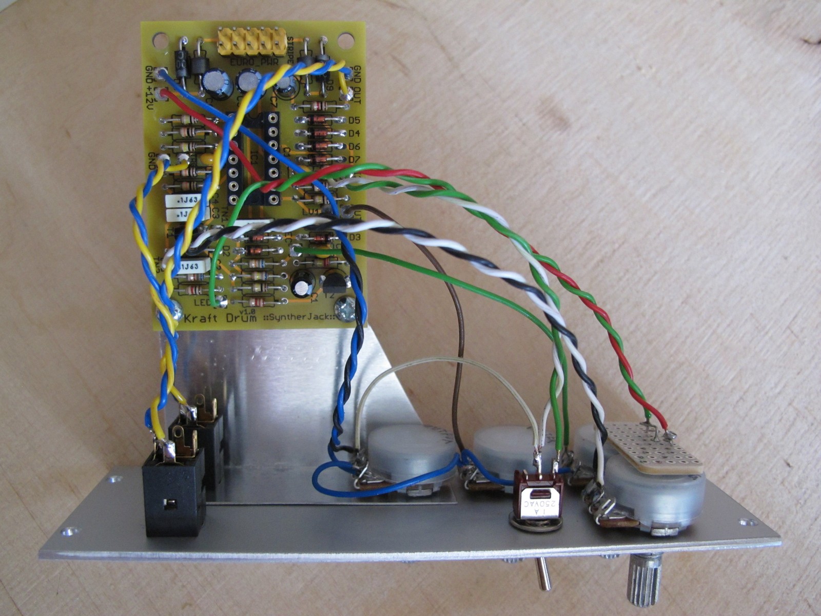
And the last last thing – zip the wires to make your module look even more pro. You can also put potentiometer knobs. I use 10 mm aluminum plated GSL10 type, they have great price/look ratio. Only 0,3 euro per piece.
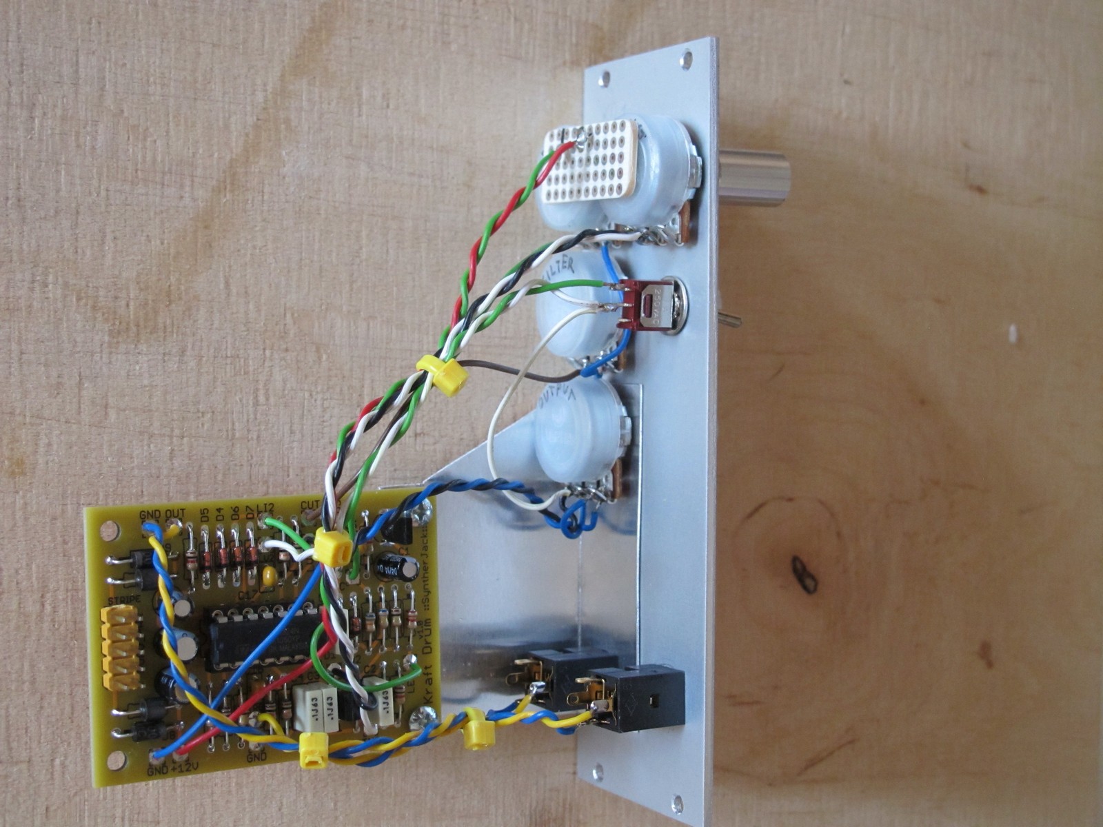
The access to solder side of the PCB is easy in case you want to make troubleshotinge of the module or just modify it.
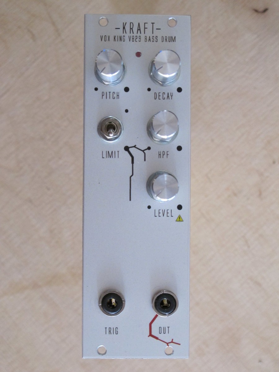
The module is ready!
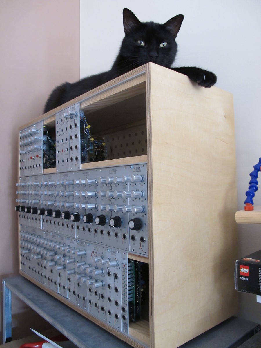
I wouldn’t say it is build like a tank, but almost all of my modules survived a 2 meter drop tests performed by my cat (named Totoro).
Now you should go and make some electrical tests, but it is another story…
Cheers
Jack
great tut on wiring, im about to do something similar, and i cannot stand no more using random gauge, dirty and recycled wire, so, this time i would love to buy some shiny and new 🙂
do you have an advice on what/ where to buy?
have a nice day, and thanks for the tutorial.