On Monday I have noticed, I don’t have a TR808 rimshot module in my drum setup. I decided to make one.
The research
808 sound modules ale very popular in eurorack world, so the first thing I did was some small research. I found modules from Acidlab (8RS), Analog Soultions (RS88 and CL88) and TipTop Audio (RS808). Original rimshot / clave circuit have only LEVEL setting (and RS/CL selection switch). All manufacturers added TUNE control, TipTop Audio went step further and implemented SNAP setting, Analog Solutions was able to split this simple circuit into two very simple ones (separate RS and CL modules). I’ve spotted some more potential in the curcuit, so I gave a try to modify it slightly.
The circuit
Roland made a great job by making clear service manual for their TR808 drum machine. I marked some possible modification points.
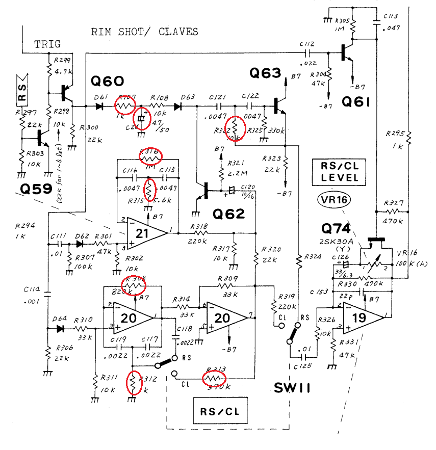
The idea is quite simple: we have two bridged T-network generators (first (GEN1) build around IC21, second (GEN2) around IC20) excited by triggering pulse. For RS output of both generators is mixed, send to VCA (build around Q62) and filter (Q63). Envelope for VCA is formed by R107 and C24 (between D61 and D63). Part of GEN 2 acts as buffer. For CL setting GEN1 has no impact on sound and GEN2 topology is changed by addition of feedback loop (R313). VCA and filter are not used here.
The ideas for modding (marked red) were:
- tuning of both generators (via one of resistors in T-network),
- filter tuning (R322),
- envelope tuning for RS (R107 and C24),
- decay time setting for CL (via R313).
After some time I noticed I don’t know how actually real clave looks and sound like. From what Roland presented, it was some kind of “ping-machine” 🙂 I downloaded some samples, looked at spectrograms and decided to improve CL circuit by adding third generator. It works at the same frequency as original GEN2, so you can use tuning knobs to get detuned oscilators sound. The schematic looks like this:
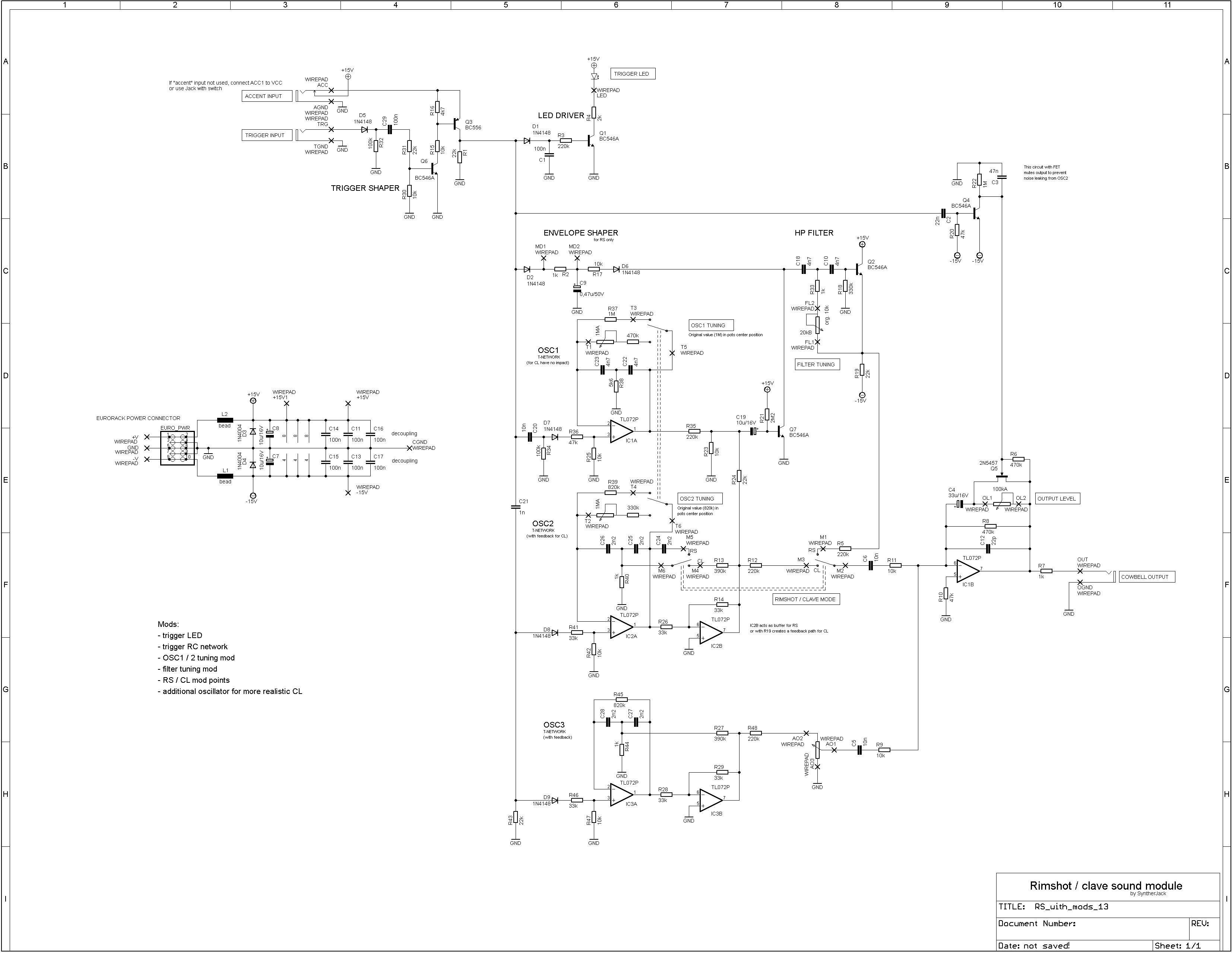
All parts are very easy to get, no obsolete components here.
The prototype
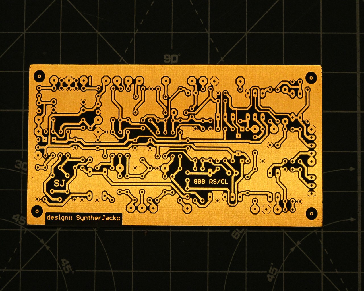
I have designed the PCB with some mod points, etched it, then started to test if all mods have sense. My trusted synth shoebox was very useful.
Most modifications were uninspiring and made “meh” difference, so I stayed with the generator tuning knobs and third extra generator output level. As always I’ve added some trigger indication LED – very handy in the first stages of any troubleshooting (and blinking modular looks also great).
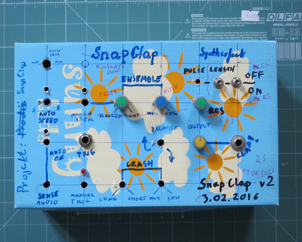
The last thing was to make a front panel, wire the whole thing and put it into my system.
The module
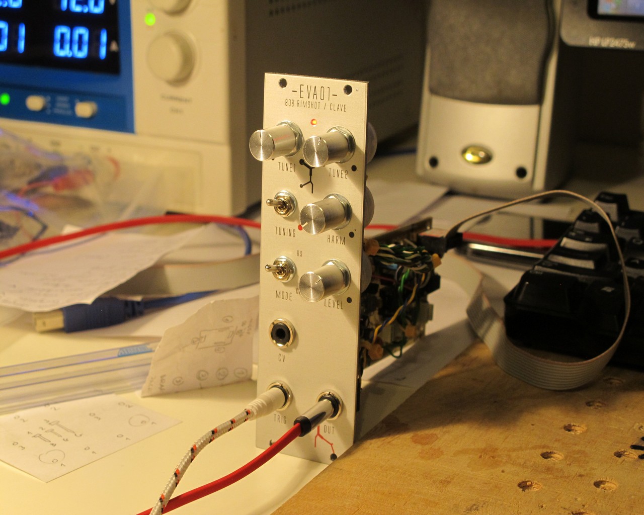
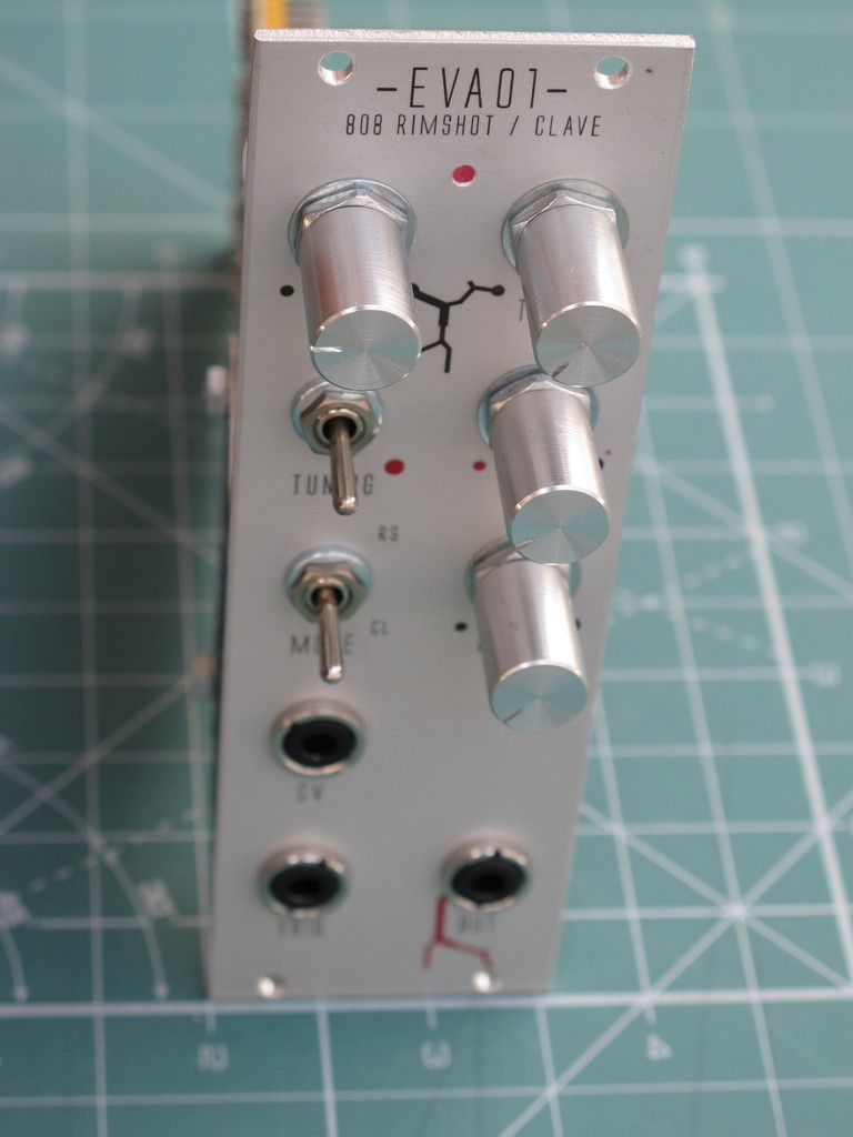
Front panel is made of oxidised aluminum with water decal on it. This combo looks well, is quite easy to make will last for a long time (I hope).

I named the device after one of the Evangelion movie “characters”. There were some little tweaks in the circuit after I soldered the PCB, so some components (resistors) are mounted on the front panel switch (the mods are already on the schematics). The module controls are:
- MODE – RimShot / CLave selection switch,
- TUNING – original / tweaked setting switch,
- TUNE1 and TUNE2 – knobs for generators tuning,
- HARM (harmonics) – third generator level,
- LEVEL – output line signal level.
Inputs/outputs:
- TRIG – trigger input,
- CV – accent signal input,
- OUT – drum sound output,
- trigger LED.
Module works with +/- 12 V supply and draws about 10 mA from each rail.
And how it sounds? Like 808 rimshot. The clave sound is much more alive now in my opinion.
Cheers
Jack
Hey Syntherjack, thanks for posting this insightful article! Here are just some observations I made while playing around with the above circuit. I breadboarded the circuit, but in lack of a +-15V-supply I ended up using a +-12V-supply. Everything is working fine except that the claves do not sound quiet right. I assume that the corresponding bridged-T-network isn’t getting enough feedback to self-oscillate. It sounds more like a woodblock — which is still nice. I think one has to lower the value of R313 (original schematic) for 24V-operation. Furthermore, the choice of transistors in the filter-circuit seems to be critical: BC550Cs (high-gain type) do not work the way they should while with 2N3904s it sounds more like it (these were the two npn types I happened to have lying around). The circuit is a cool addition to a TR-606 or any other drum machine with trigger outs! 😎
Regards
Alex
Thanks for your observation! I will include those in post as additional info!
Hey, in order to confirm my wild guess I replaced the 390k resistor by 220k and now it sounds more like the 808 claves. The network gets considerably louder when it self-oscillates, but I guess this is just normal. (VCFs usually behave the same.)
Regards
Alex
Hi Syntherjack, I had a question: what is the use for the MD1 and MD2 wirepads in the schematic? I assume this is for modification to the envelope shaper, which did not make it in the final design?
Hello, usually I add MoD pads if I hope for some easy and fast to check mod – in this case I probably wanted to replace resistor with potentiometer.
Hiya jack. Do you have a hi res copy of the pcb circuit layout for etching?
Whilst on the subject of etching, are you in the future thinking of adding to your brilliant panel making blog by showing us how you go about etching your boards? Many thanks Ryan
How is the output of this and your other drum modules? Is it eurorack level (10vP-P) or closer to line level 2v? If its line level, any thoughts on increasing the gain? would an increase in R8 increase the gain? Or maybe decrease R9 / R11? Thanks!
> For CL setting GEN1 has no impact on sound and GEN2 topology is changed by addition of feedback loop (R313). VCA and filter are not used here.
Thanks for the write up – it’s really useful! I have one question if you don’t mind. I can see how the filter circuit is disconnected when the RS/CL switch is set to CL, but how come GEN1 and the VCA aren’t in play for the clave sound? It looks like they would still be connected. I’m sure I’m missing something obvious.
Hi, thank you for share this wonderful circuit, I am lost with the conectons to teh switches and pots, is there a conection diagram?
Thanks again
I am trying to work out exactly how you mounted the PCB to the front panel. I can see a piece of metal to which the PCB has been screwed but I have no idea how that piece of metal is attached to the front panel. There are no clues on the front panel either. Can you enlighten me? Cheers Ian