Tetsuo eurorack power supply indicator was my first eurorack module and it detemined the graphics for my entire modular system. It was inspired by “Akira” movie stadium scene, when Tetsuo, sitting on the concrete armchair, sets free his power. To be specific, I made two versions of Tetsuo – one with power socket and one without it.
The idea and first build
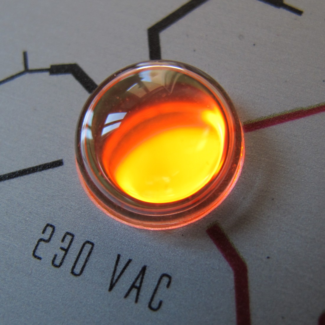
It is just an power supply indicator, so there’s no big thinking behind this 🙂 The neon lamp indicates the presence of 230 VAC voltage on the PSU input and the three orange LEDs shows the +5, +12 and -12 VDC on the synthesizers power supply rails. The first version of Tetsuo (from around 2013) had separated +/- 15 VDC LEDs – I thought somehow the two voltage level system is a good idea (no, it wasn’t).
Tetsuo One was inspired by Q102 power module by synthesizers.com. It was a bad idea – mains cord was very bulky and not handy in eurorack (dotcom format is much bigger and sturdy). The module was 12 HP and I don’t use it anymore – it’s in my Hall of Shame right now).
Tetsuo II
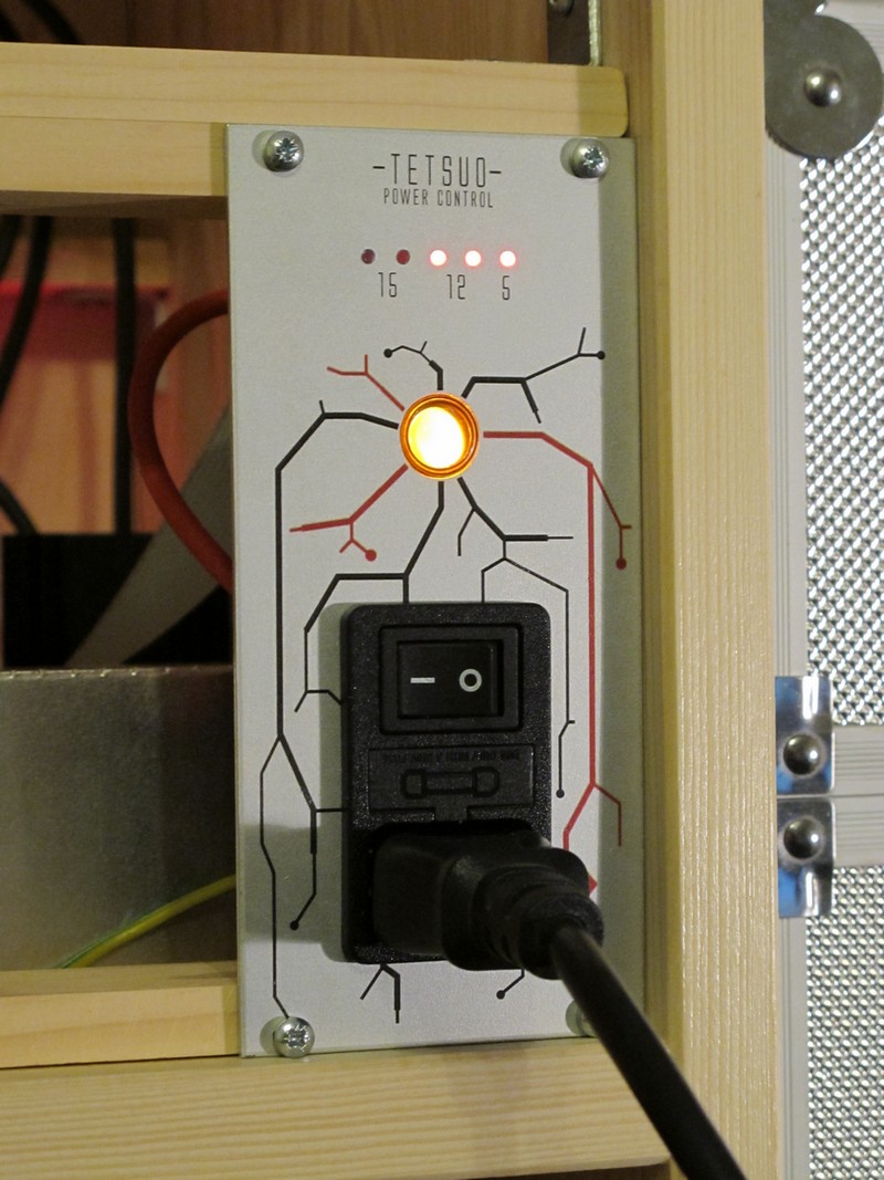
In the second version (from 2017) I’ve got rid of power socket with switch and moved it to the back of my new case. As a result Tetsuo Two was born – the module is 8 HP width and shares a lot of design with Tetsuo One.
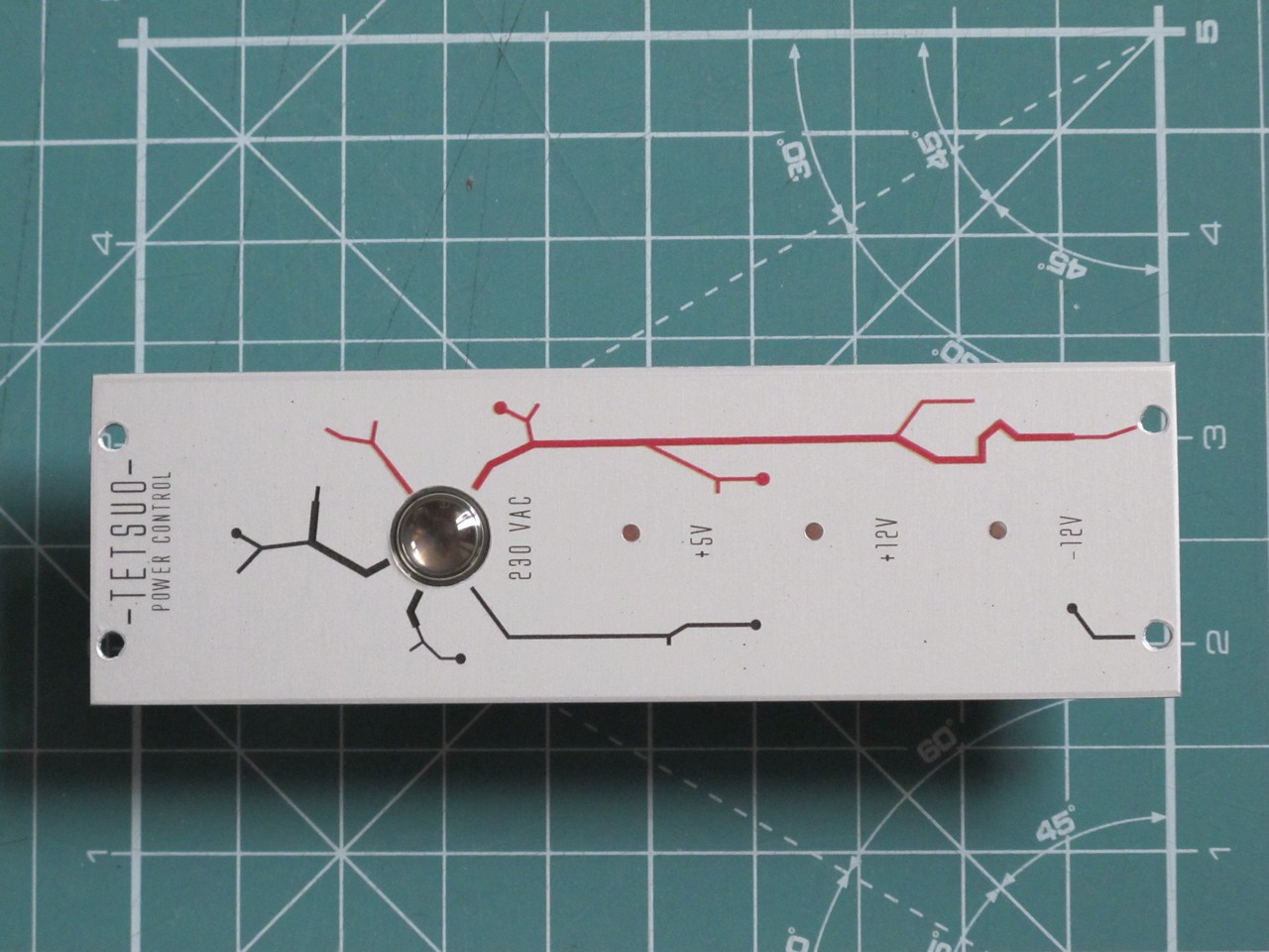
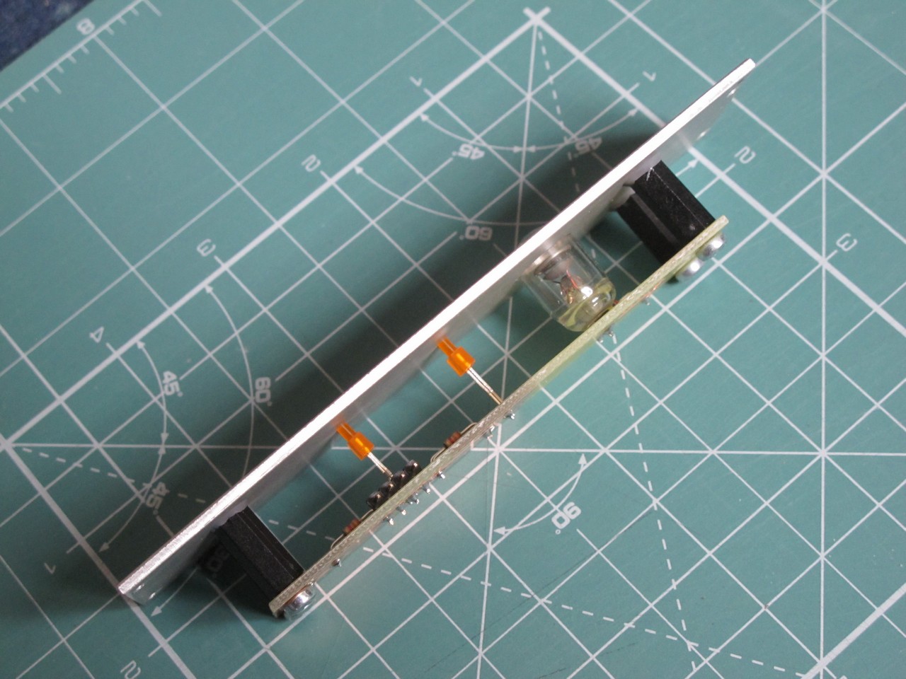
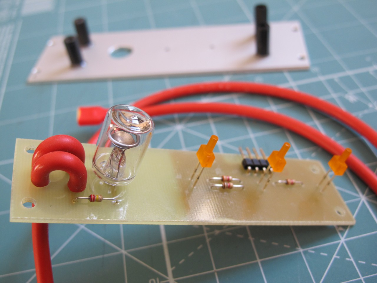
The low level voltages are connected via small 1×4 raster connector (there was no space for standard 2×5 eurorack power connection) and the mains via soldered, silicone polymer / foam insulated wires. The PCB is glued to the panel with AutoWeld adhesive.
The neon lamp (I don’t know the exact type) was a big suprise. I’ve got around 30 of this small beauties and all of them had slightly different diameter and length (!). I realized this after I drilled the holes and put the water decal. From 30 only 5 fitted, and from those 5 only 2 met my tight equality-of-brightness specs. Furthermore I accidentally destroyed one of them – they are really fragile.
Since I build Tetsuo One, I try to keep a certain LED color scheme:
- red for triggers and binary states,
- yellow for level / overdrive meters for audio signals,
- orange indicates power supply voltage presence,
- blue are banned, because blue LEDs look cheap.
So, in second attempt to PSU indicator panel all LEDs are yellow, they also harmonize with neon lamp very well.
Schematic
The schematic for Tetsuo Two is incredibly simple:
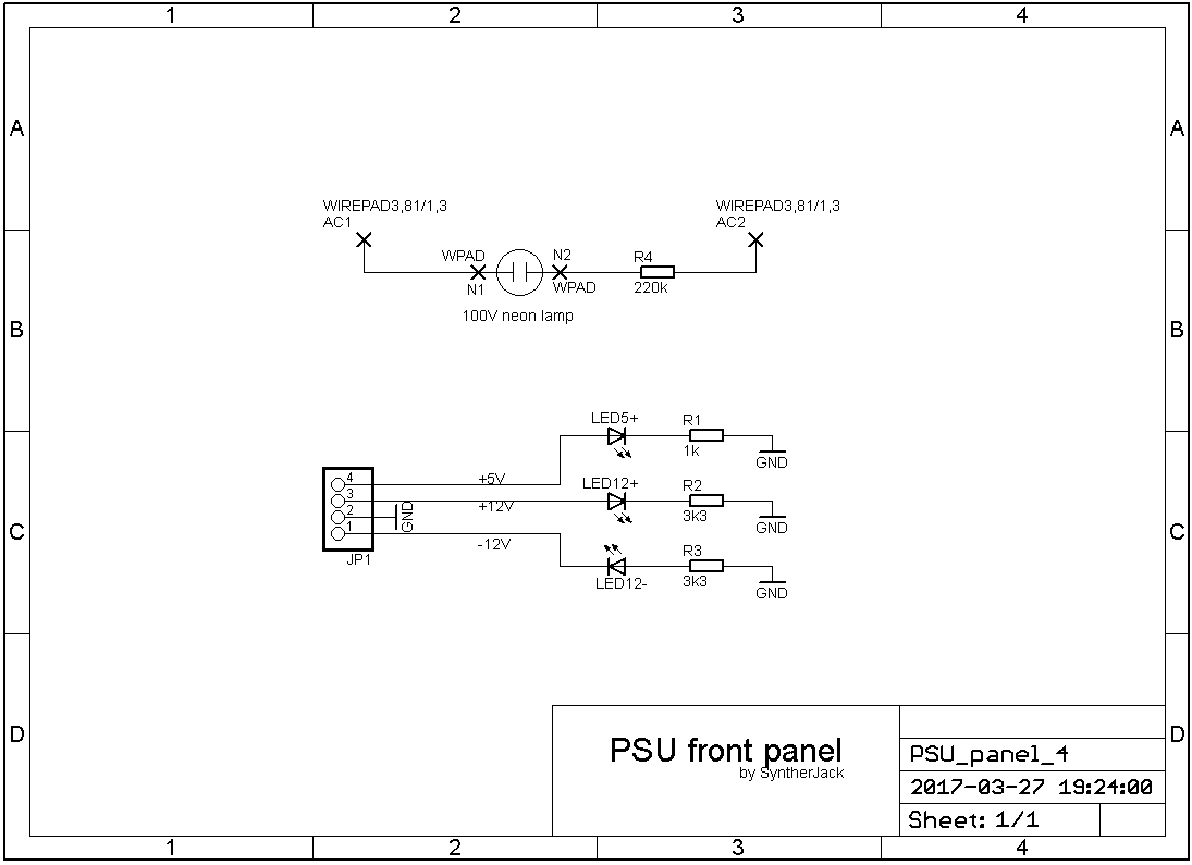
The LEDs are OSO5JA7K94B from Optosupply. The neon lamp ignites at 100 VDC and comes from the ’70, it was used in old polish frequency counter – I wasn’t able to save the meter, so I removed the indicators and nixies. I didn’t want the indicators to use a lot of current, because it is better save it for real synth modules. The resistors were calculated for ~2 mA LED current and ~0,5 mA neon lamp current. As lamp is connected to AC voltage, it blinks with 50 Hz frequency – it is visible, but not annoying.
Safety
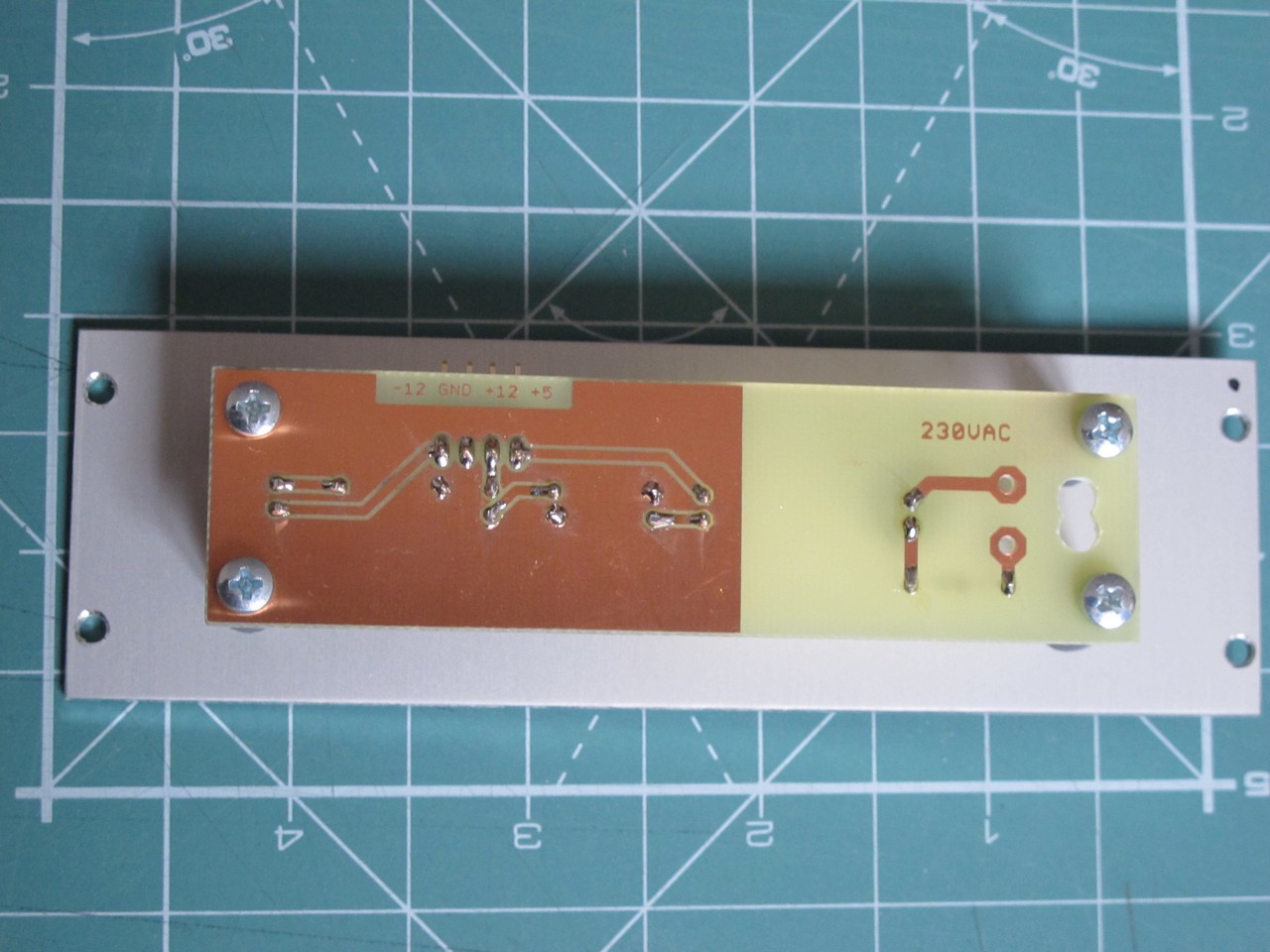
The connection of mains voltage near the front panel is always a bad idea. I’ve tried to make is as safe as possible:
- the PCB high voltage AC section is separeted from low voltage DC section,
- the PCB is covered with Kontakt Chemie Plastik 70, the protective coating (with dielectric strength > 80 kV/mm),
- then the PCB is fixed to aluminum front panel via non-conductive spacers,
- wires are well insulated and soldered directly to PCB.
If you want to inspire with my project, please remember:
Don’t mess with mains, it can kill you or even worse!
Cheers
Jack
This project remind me the HAL9000 eheh! Very nice and the final result is awesome as everyone of your project. You print the PCB by your own?
Thanks! I make most of my PCBs at home with photo-positive method. The PCB design is printed on the foil, then put onto board with photo-positive paint and exposed with UV light. Then board is developed, etched, driller until it became PCB 🙂
How did you come up with the panel ideas?
The basic panel theme for eurorack is based on Akira movie, stadium scene. And to the rest of my synths, I usually look for inspiration in vintage laboratory equipment.