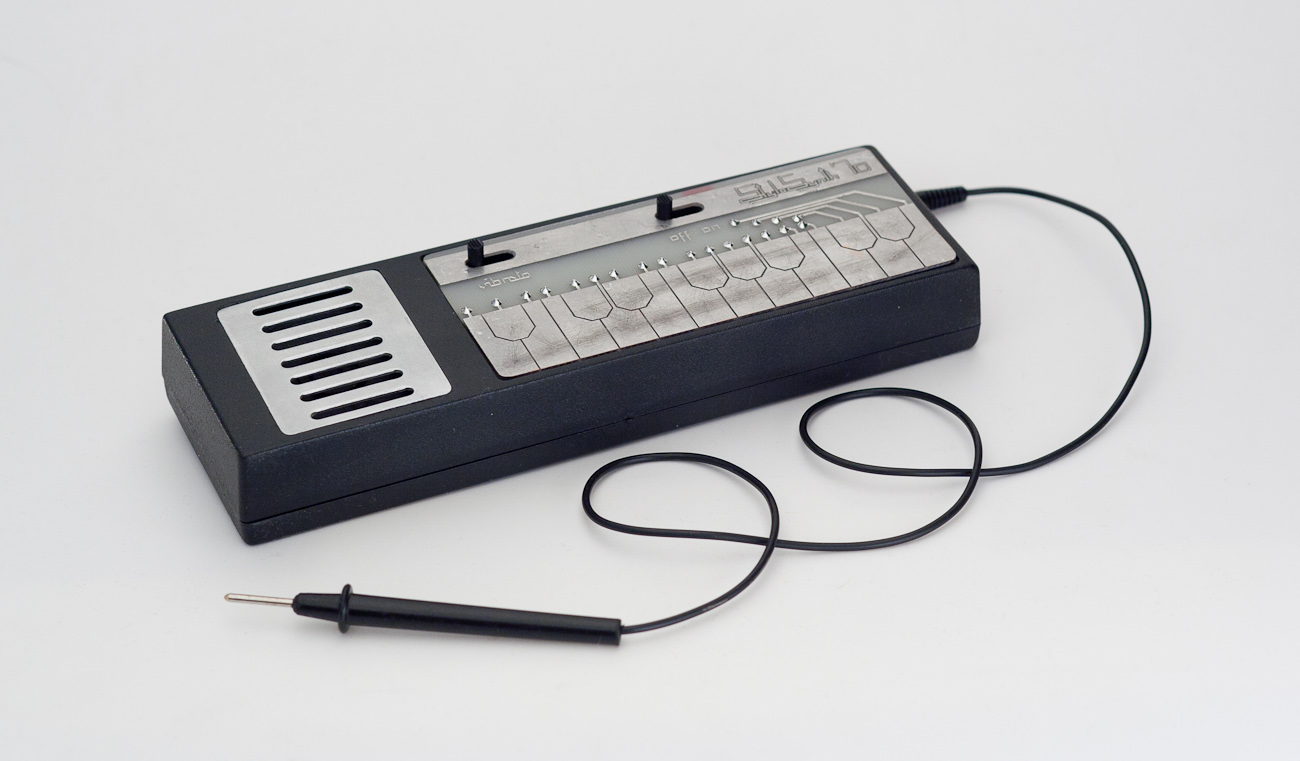
Stylophone is a portable, miniature sound synthesizer, designed around 1967 and build between 1968 and 1975. In 2006 it was put on market again, with some major modifications. Its most recognizable feature is a way of play – musician uses stylus and a metal keyboard. The similar instruments are Gakken SX150 and Dr Bohm Hobbyton.
Before I introduce my device, some history lesson.
Years 1968-1975 – the first, original production batch
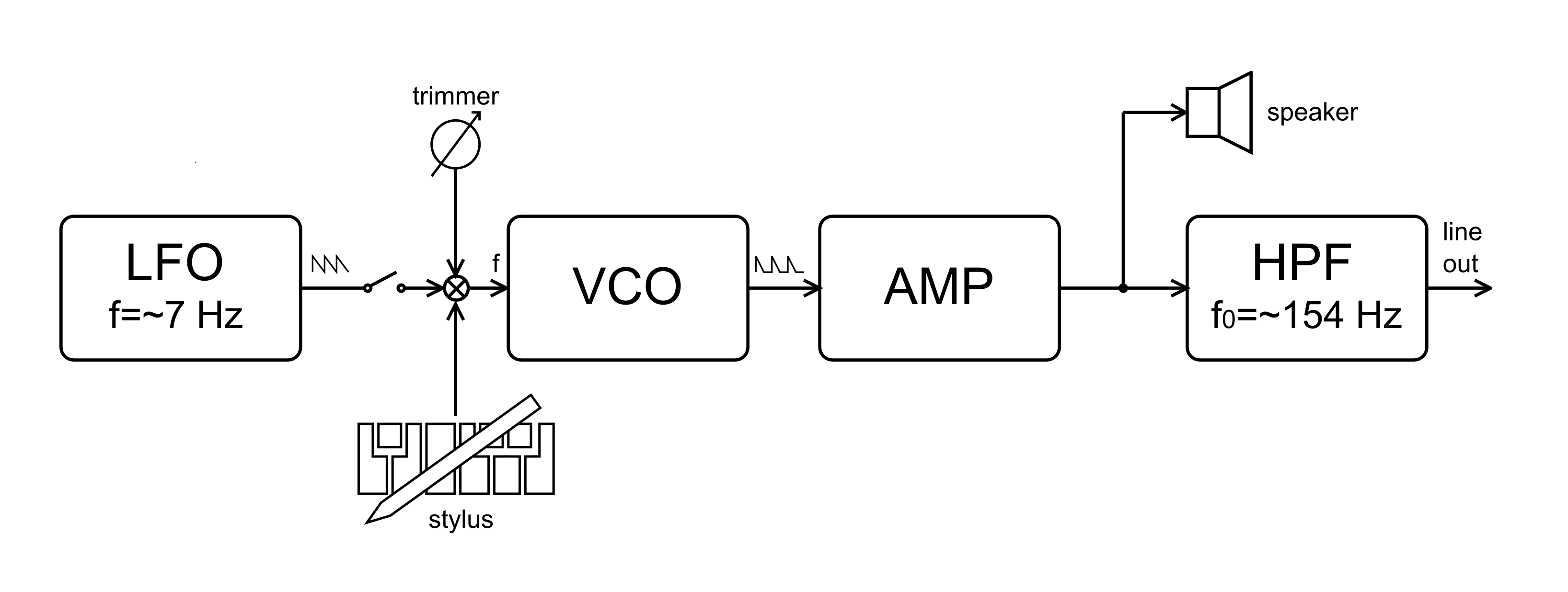
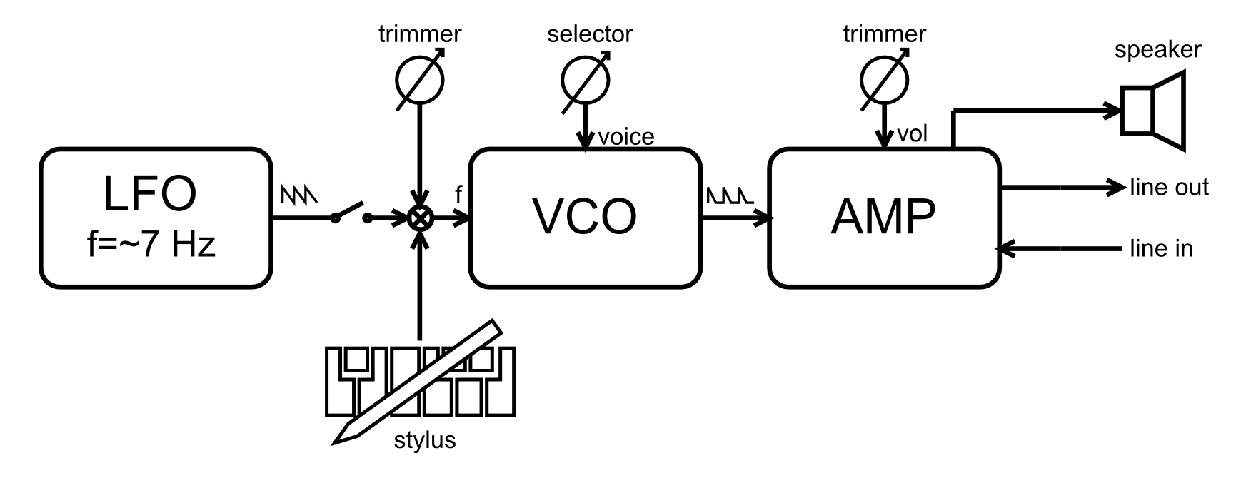
Synthesizer patch contains VCO and LFO. LFO can modulate VCOs pitch, resulting in vibrato effect. LFO frequency is around 7 Hz and the waveform reminds triangle. The user can use additinal pot on the back of the device to tune it – when battery voltage drops down, the pitch changes. The volume control was implemented around 1974 – 1975. In the first devices you just have to cover the speaker with your hand. The block schematics of the synth looks like this:
All devices from ’68-’75 have line output, but because of highpass filter (cutoff @ 154 Hz) put on it, the signal transduced by speaker is different from the one from output. Thats why musicians like to put stylophone speaker to the microphone and not use the line output.
There were 3 different versions produced: standard, bass and soprano – the diffenence between them was only in one capacitor value in sound generator circuit (a simple switch between modes would be a nice addition here).
The stylophone is not a good candidate for circuit bending – it is just too simple, most bends just detunes the generator or causes distortions. The easiest mod is to add volume control or LFO frequency potentiometer.
In the years of production of original instrument (1968 – 1975) the components and circuitry were changed three times – the most changes were related to generator design (please check the edit section under the post):
- first version (1968 – ?) – capacitive diode and unijunction transistor (relaxation generator),
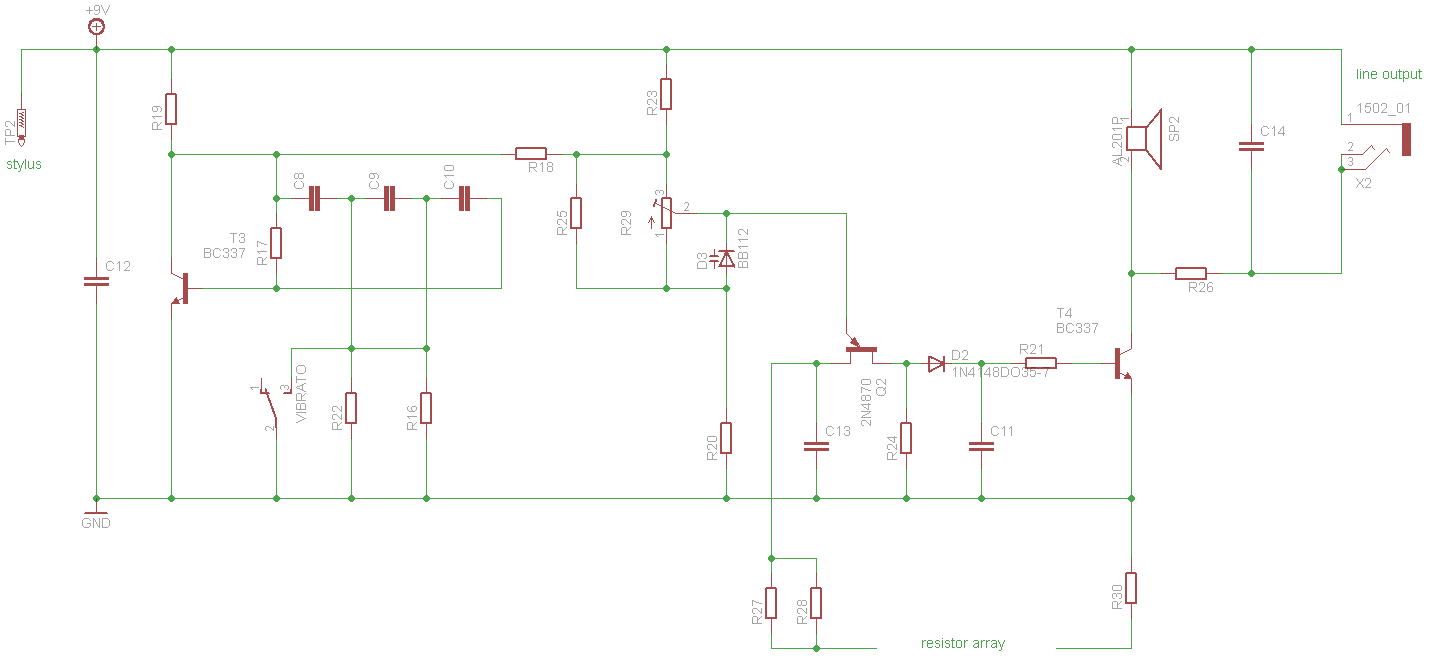
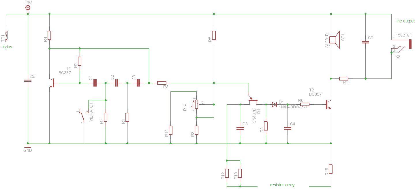
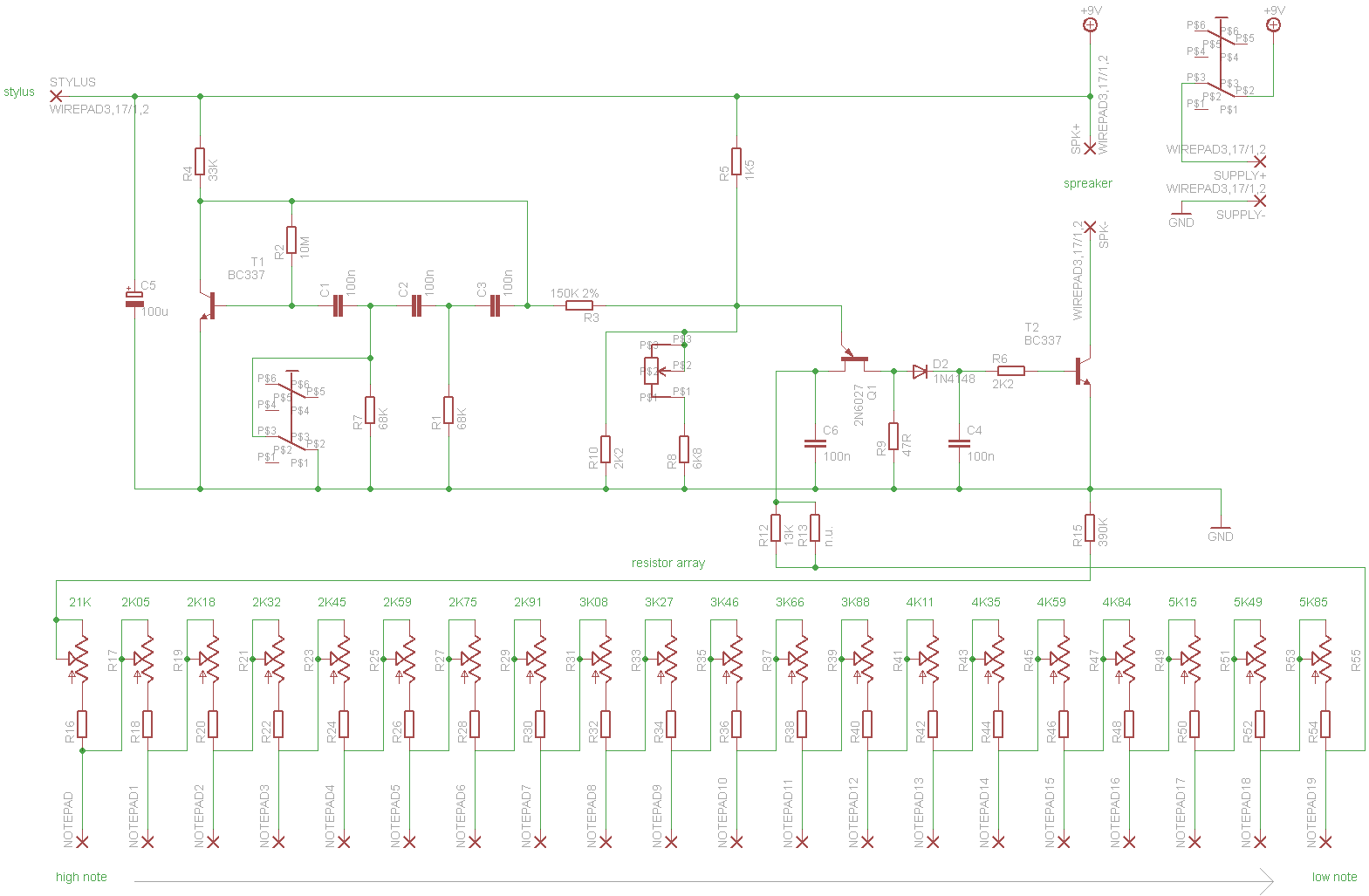
- second version (? – about 1974) – unijunction transistor (relaxation generator),
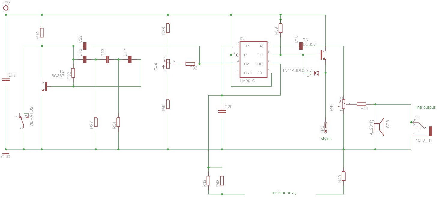
- third version – (about 1974 – 1975) – 555 timer IC.
In the first designs, the resistors in keyboard circuits were created from single resistors (usually non standard values), later single resistors were replaced by integrated circuits (IC contained 10 resistors). You can clearly see – the later the version, the simpler the circuit (some say also worse sounding).
The first two revisions, using relaxation generator, produces quite unusual waveform (for today synth standards), reminding a series of pulses (or sharks in the sea if you change oscilloscope channel amplification).
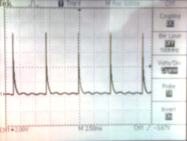
The latest version is just boring squarewave out of 555 🙁
After 2006 – latest batch
In the year 2006 the production was restarted and stylophone (with trademark) was sold as retro-gadget. The generator is based on specialised digital IC (integrating VCO and LFO) and have little in common with original design. The transistor amplifier was replaced with LM386, line input is also here, so you can connect an extarnal sound source. The user can choose from three predefined sounds (better late then never :)). The block diagram looks similar to previous version, but most of it sits in a digital IC.
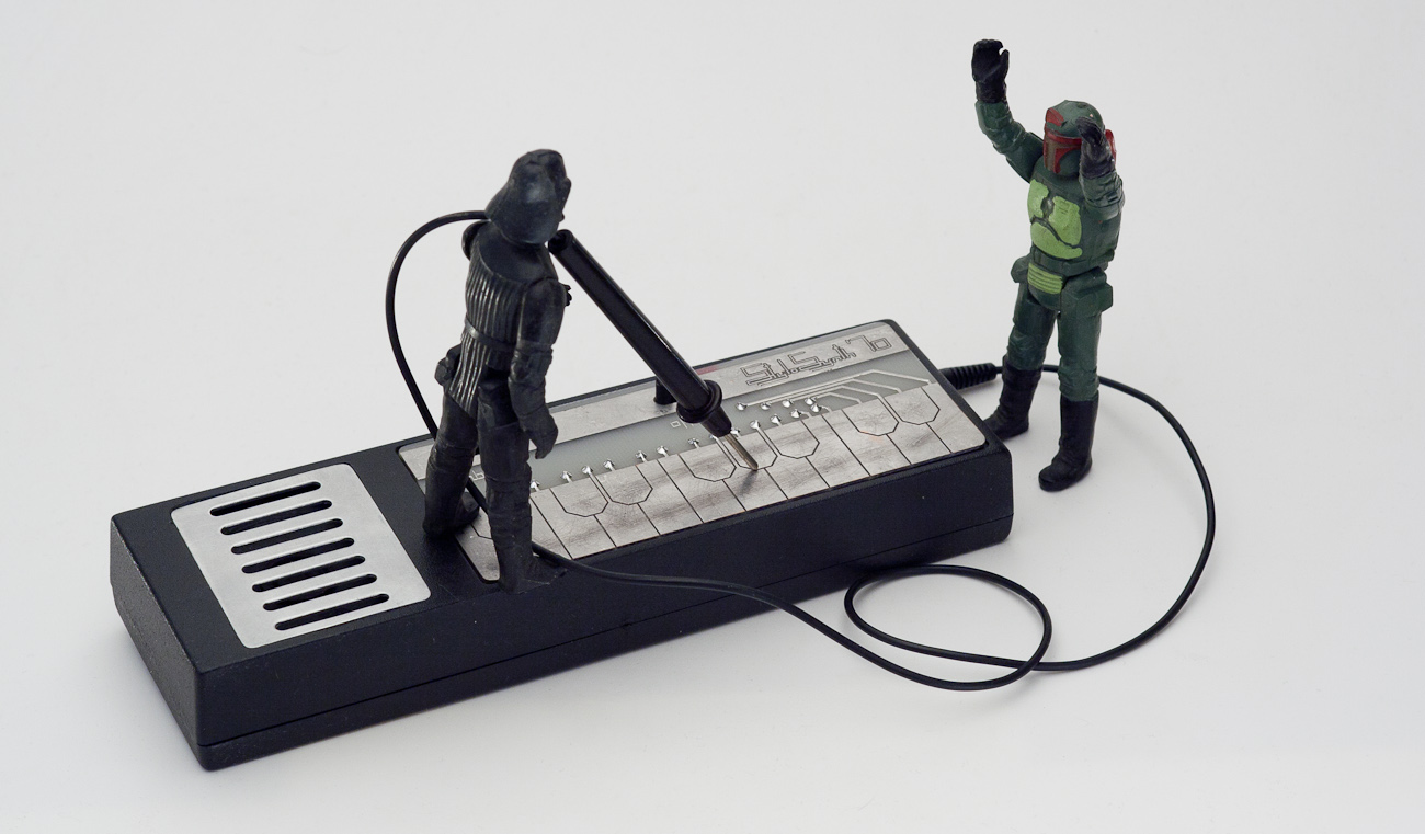
Stylosynth’70
I have chosen the second version – simple, analog and beautyful. I have called it Stylosynth’70. All components were easy to obtain – the only problem was 75 ohm speaker, I have replaced it with 50 ohm one.
Synth was build inside standard “TV remote” enclosure. It has nice separated place for 9 V battery. The front panel was etched in the same way as PCB. The speaker cover comes form an old polish laboratory voltometer.
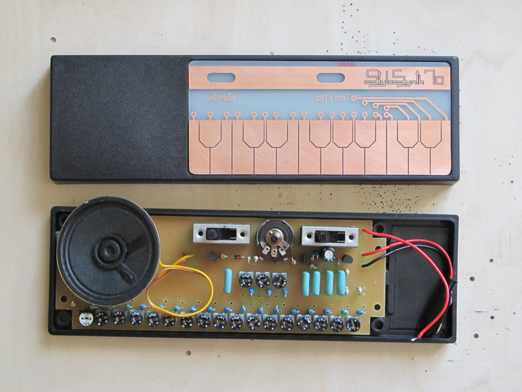
The stylus comes from cheap multimeter. The whole synth price was closed in 10 euros.
And how it sounds? (beware of ancient low quality video from 2011). Recorded using microphone. Rocky theme. Say no more.
Sounds very ’70 :/ Unusual for shure.
Jack
edit 24.06.2017
I’ve got a comment on my old clay/electronics blog:
“You are wrong here. the real 1-st generation Stylos seem to have in fact 2 normal transistors for the main oscillator. You might want to verify that, so here is the patent, see page 5:
https://worldwide.espacenet.com/publicationDetails/originalDocument?CC=GB&NR=1160839&KC=&FT=E
and here are the insides of the 1-st mass-product generation, 2 units (both with the 2-nd and the 3-rd ones).
https://andymurkin.wordpress.com/2012/07/21/stylophones-2-variations/
arent there 2 normal transistors as well, like in the original prototype schematics?”
I totally agree with it. At the time I wrote this article, the mentioned sources were unavaliable. Thanks!
Hi.
What do you mean by cheap multimeter for the stylus…wanted to get a second stylus for my stylophone to play chords potentialluy
Hello, I got some really cheap analog one for below 2 euro. Its quality was awful, the only good things were probes. I just cut them and blunted. Bur now, you can just order probes from Aliexpress or similar for few pennies…
You should take part in a contest for one of the greatest blogs on the
web. I will recommend this web site!
If I find such a contest I will sign in 🙂 Thanks for kind words!
Hello, I’m a newbie at Electronic, so it’s a little difficult to understand the circuit(because I dont know all component’s schematics), but I really want to build it, Do you have any list of what components I need?
Thank you, Lucas
Hey,
I’m trying to figure out what wattage resistors this circuit uses. I’m assuming 1/2W or 1/4W, but I want to be sure. Also, on the keyboard resistors, what is the resistance on each note? Is a 2K75 a 2K potentiometer and a 75 ohm resistor, or a 2.75 ohm resistor?
Hello, 1/4 W 1% should be ok. It was long time ago, but I bet 2K75 is the target resistance you should get, so 1% 2K7 resistor and 100 ohm trimmer. Cheers!
another feature of the real first version (the 4-transistor one) is that “vibrato” is likely tremolo in fact. the thing also lacks any diodes.