This article was updated slightly on 21.05.2018 and includes filtering capacitors change and some output voltage measurements.
Introduction
Every modular synth needs a power supply (except systems containing only blanks and Giskies 12 HP Bottle Openers). Switched power supplies sometimes cause problems (when you have a lot of small modules, all with input power filtering caps), so I moved to a proven solution. My synth power supply unit is based on Doepfers Modular PSU, but has few little upgrades:
- uses more popular, cheap heat-sinks,
- better quality capacitors,
- protection diodes,
- changed connector spacing, for easy operation,
2 x 1,5 A output @ 12 V (tested), but will go to around 2 A on each rail,
- 2 x 2,0 A output @ 12 V (tested) – 21.05.2018 update.
Total cost of the PSU is about 20 euro (with most money “eaten” by toridal transformer).
The schematic
The schematic is very simple – just a popular linear power supply based on LM317/337 pair. I used 2 x 15 V, 2.1 A, 60 VA toroidal transformer. Notice there is no fuse holder on PCB – it should be right after mains socket and before on/off switch. Filtering capacitors C1-C4 can be 25 V rated which is correct if PSU is loaded. If no current is draw from outputs, the input voltage can get close to 25 V, therefore is is a good idea to use higher rated electrolytic capacitors, f.e. 35 V (which was marked on the schematic).
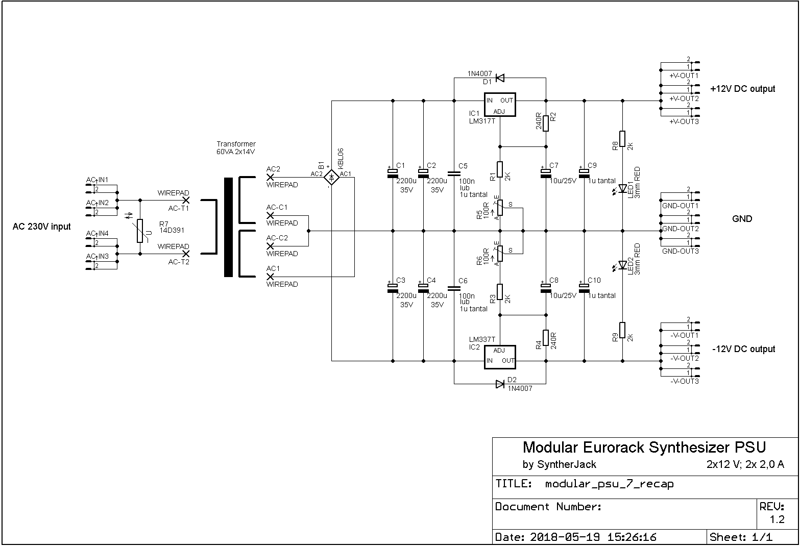
For LED resistors R8 and R9, any value between 1 and 5kΩ should work. 2kΩ is only to reuse R1 and R3 value and consequently make BOM (Bill Of Materials) a little shorter. R7 (yellow disc) is a 14D391 varistor and acts as overvoltage protection.
The PCB
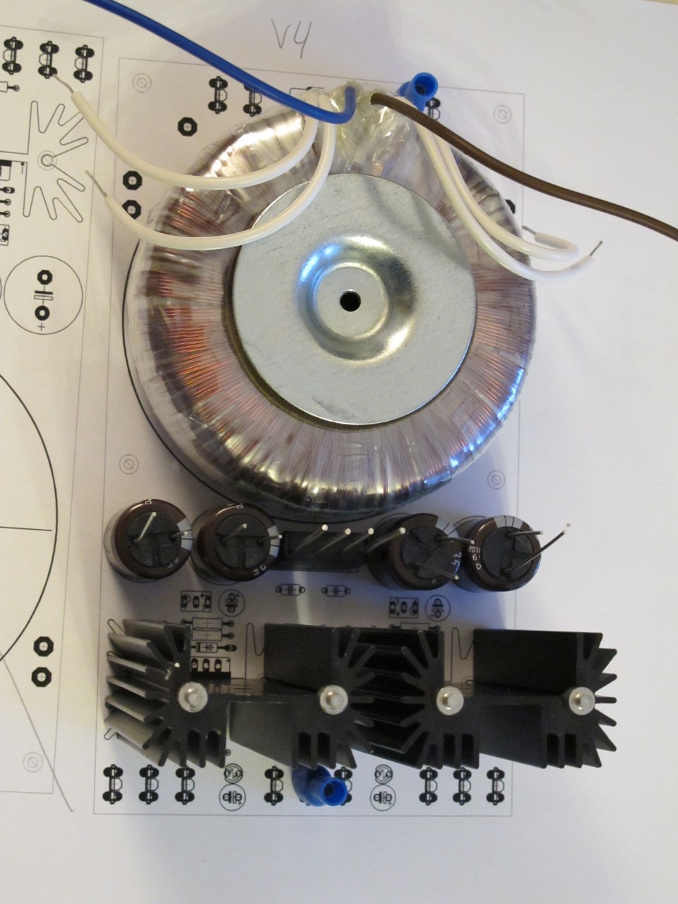
I always start the PCB design with fitting major components on printed PCB layout. There is nothing more annoyng then see that componets don’t fit after you spend 2 hours on cutting, etching and drilling. It takes only few minutes and can save a lot of time later.
I made a PCB with Bungard FR4100X160/3500 laminate with light-sensitive coating (I don’t use Positive spray after a cat has chosen me as his owner – fur everywhere). Size of the board is 100 x 160 mm. All project files are added as attachement at the end of the post.
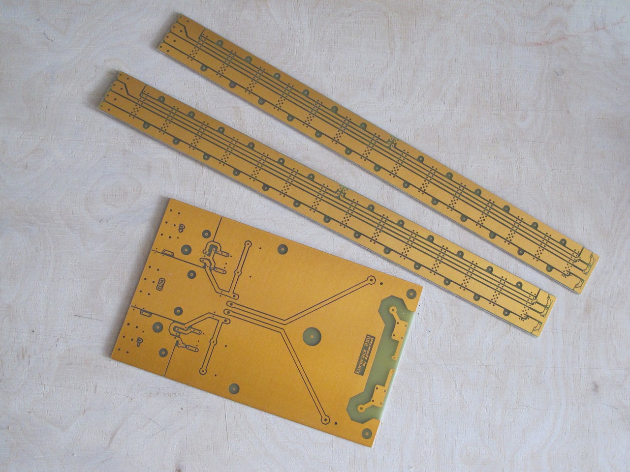
If you are interested in making your own busboads (simple, but reliable), you may want to read this short article.
The build
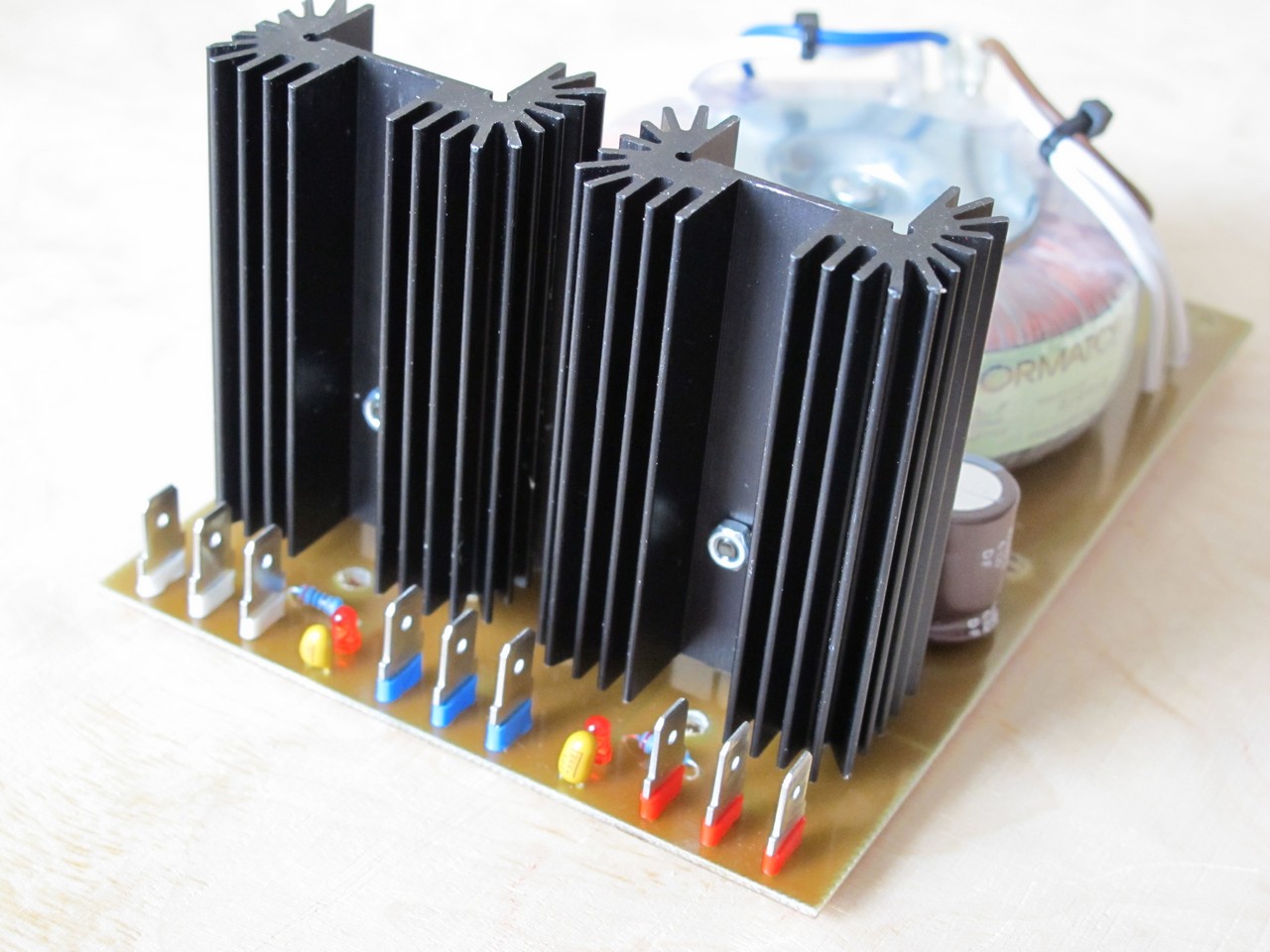
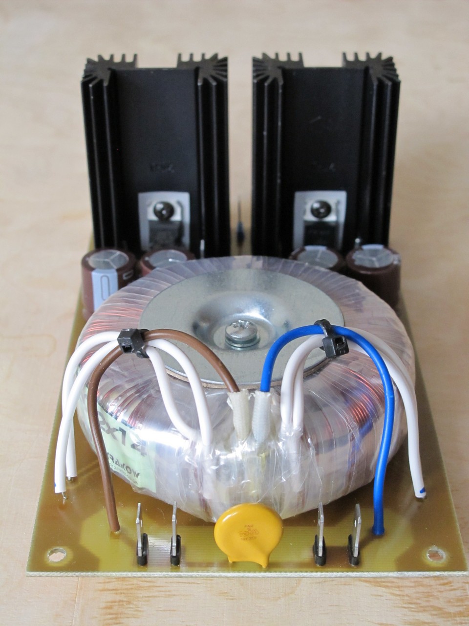
Vertical-oriented heat sinks make PCB size smaller, but at the cost of its hight. Most of the PCB is occupied by toroidal transformer. There is a place for 6 screws to keep this quite heavy device on its place.
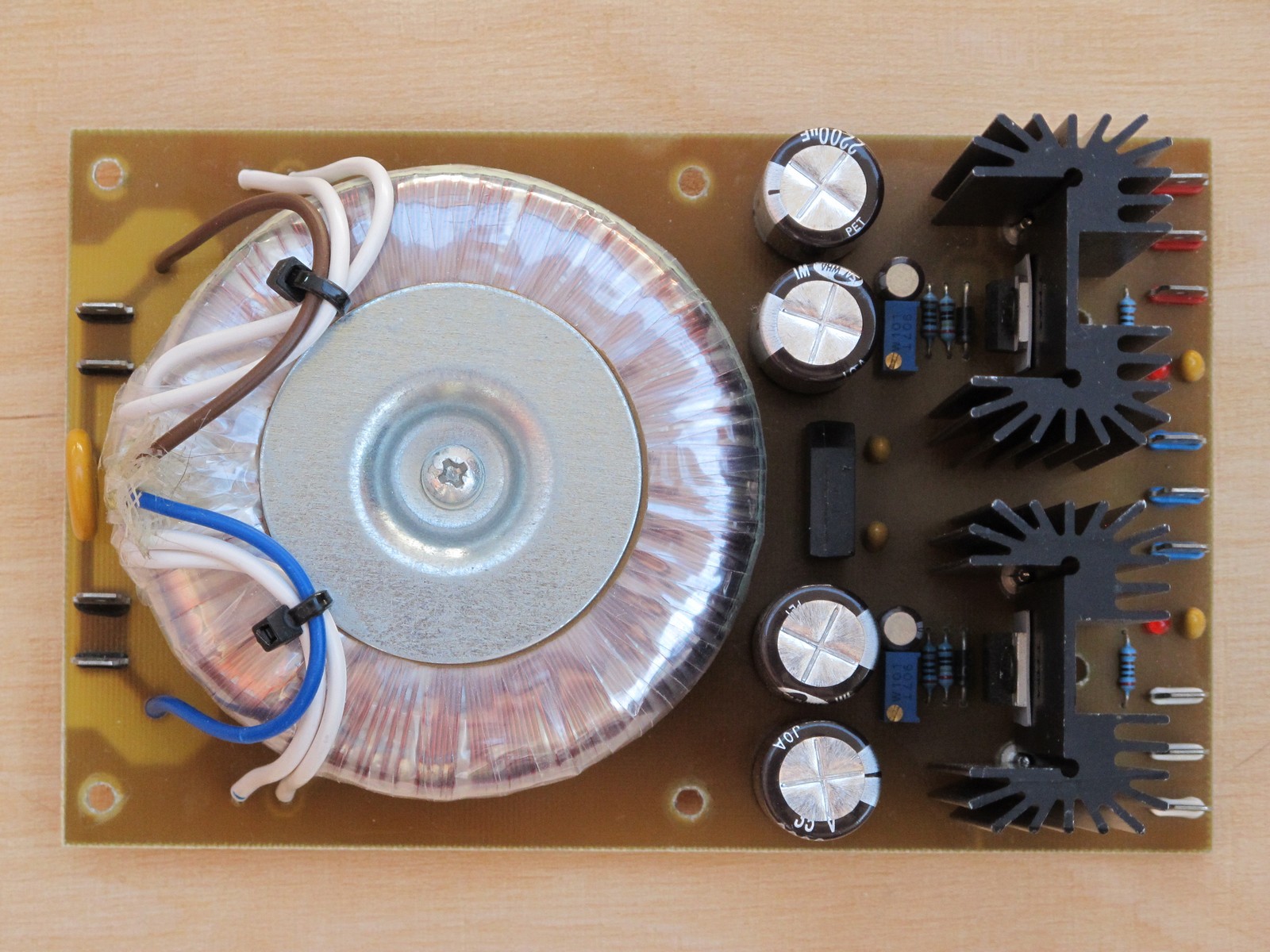
6.3 mm outputs are marked with pieces of heat shrink. You can connect up to 3 bus boards. The small red LEDs inform you that there is something on power output, but what is more important, they let linear voltage regulators work properly when nothing is connected. The also help to discharge filtering capacitors if no load is applied.
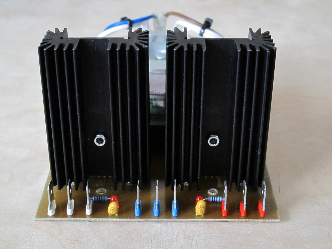
Silicon isolators under linear regulators ensure there is no eletrical connection to heat sink. They are not needed if you are 100% shure that the heat sinks will never touch. But you never can be 100% shure 🙂
The measurements (added on 21.05.2018)
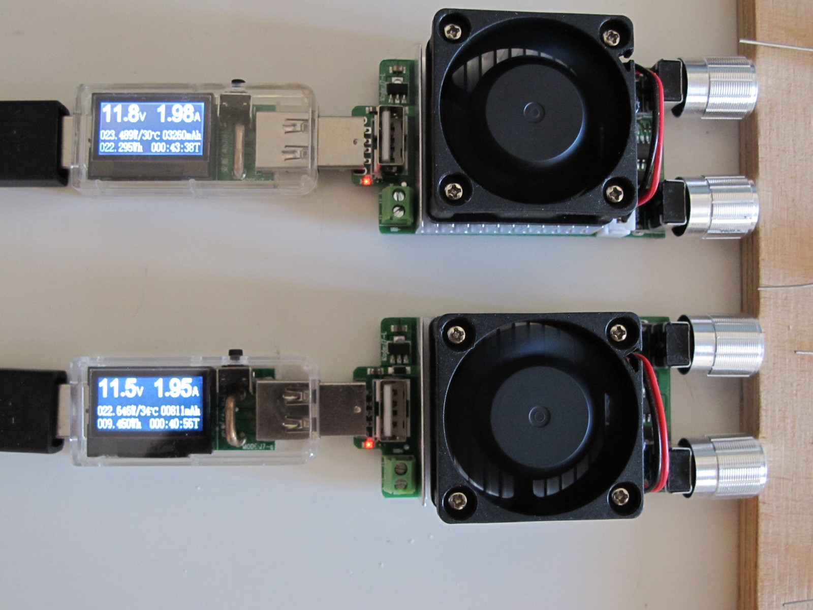
Now lets look how the output waveforms look like. I made a simple testbench for my synth power supply using USB multimeters and electronic loads. Later I have repeated the measurements with old-school resistor load (4x 2Ω, 10W) as I had some problem with electronic load.
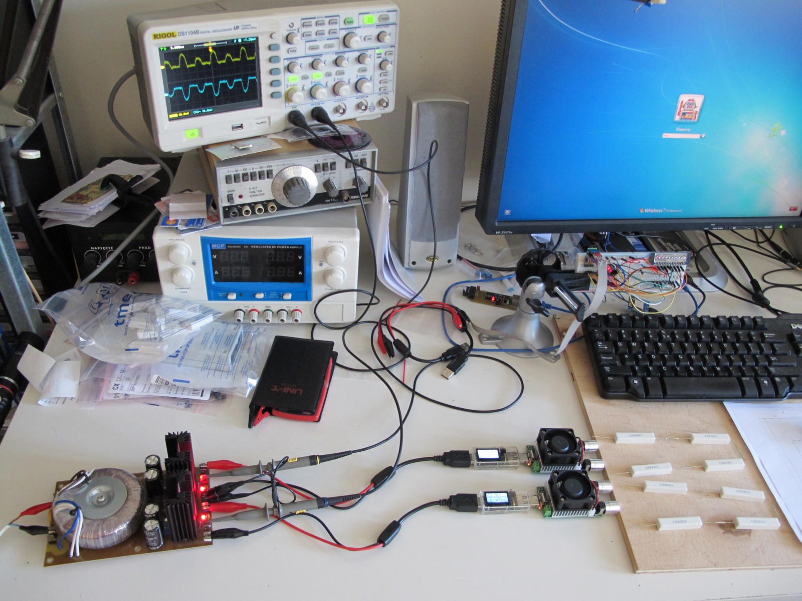
All voltage/current values were double-checked with the adult Brymen multimeter. USB meters are not very accurate (especially voltage measurements – in reality for both channels output was around 11,9 V).
I made measurements for “old” 2x 1000 uF input filter (a,b) and “new” 2x 2200 uF filter (c). The recorded output signals for both positive and negative rail look as follows:
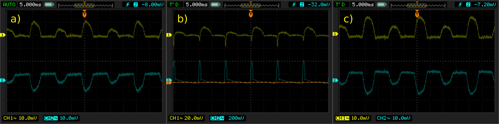
When using 2200 uF filtering capacitors, for 2,0 A current draw from each rail the ripple voltage is below 20 mV p-p. Not bad, but also not the cleanest output ever – still OK in most cases.
Hope you will make somethig useful with this knowledge, but remember:
Before you do anything, remember: ~230 V can kill you with no problem. If you don’t have experience with mains voltage, leave it to someone who has. You are using the project files for your own responsibility.
Cheers
Jack
Hi
Thanks for sharing ! 🙂
Do you have the pcb typoon of the bus board ?
oooops…. i answer myself , just found it browsing your website !
https://syntherjack.net/modular-synth-busboards/
thanks !!! 🙂
Hey! If you change R1 and R3 to a 2k7 and put on a 2x18v transfo, Can you make this psu into -/+ 15v? 🙂
Hello, if you calculated R1 and R3, it should work. Don’t forget to change capacitors rating to 35V!
Thanx! Your site is a diy goldmine 🙂 Keep up the good work!
Thanks! And don’t forget to check the PSU output before you connect any module!
Ever thought of making a PSU with +12/-12 AND +5V outputs?
Not really, for eurorack I use 5 V adapter: https://syntherjack.net/5v-eurorack-power-adapter-for-1-euro/ But in the past I’ve build small portable PSU for analog circuits testing with +/-12 V and 3.3/5/9 V selectable. Cheers!
Thanks for sharing this. Big fan of your site.
By any chance do you have PCBs for this PSU? Or do you think it would work if I adapt it to stripboard?
If I were to make it external to the case and use triple core wire to connect to it, would it be a problem? I still don’t fully understand how impedance would affect this, if at all.
In my build I use 2200uF/35v, but my output voltage is like 12,9V, how I can decrease this value to straight 12V?
What kind of fuse would you recommend to use?
Hello i want to Bay a pcb board front your clapsnap but i can not see IT one your site van you help me please Gr bas van Rossenberg