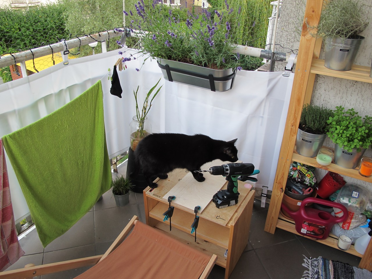
One day I decided to move my modular drum synth into bigger case. The main reason was my girlfriend wanted to use my previous Ikea Rast style case as an balcony table. I had no choice.
The plans
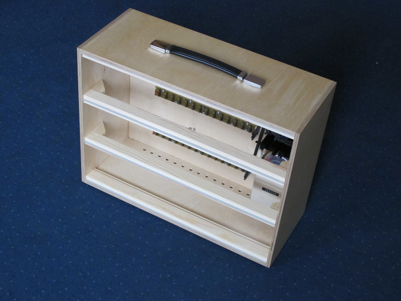
The design is based on Doepfers A-100 Low Cost 9U case. I made few “improvements” to suit my needs and initial sketches. The most important assumptions are:
- 104 HP width = 529 mm inside (I was not limited by usually sold 84 HP aluminum rails),
- height of the one module can be up to 129 mm (its a DIY, it would be hard to keep 128,5 mm as Doepfer says),
- depth of 220 mm to fit “Clangora” module (by Thomas Henry) – it’s my biggest one,
- the alu rails were switched to wooden with alu inserts – to keep the costs low,
- use of 10 mm plywood to keep the case stiff and rugged,
- no visible screws and therefore internal reinforcements,
- air vents to achieve a reasonably low temperature inside.
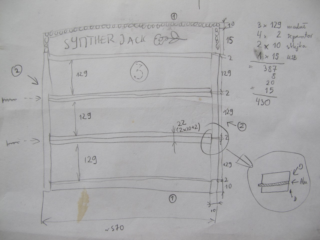
I don’t know why I wanted a add an neon or something similar on the top op enclosure (this thing with SYNTHERJACK and flower). It was a stupid idea. So, after whole planning I got the shopping list:
- hardwood plywood for box (theoretical dimensions) *:
- 2x (10 x 529 x 220 mm),
- 2x (10 x 415 x 220 mm),
- 1x (10 x 529 x 395 mm),
- wood/alu rails:
- 2x (10 x 30 x 2100 mm) squared pine **,
- 1x (2 x 30 x 2000 mm) anodized aluminium flat bar ***,
- 1x (2 x 30 x 1000 mm) anodized aluminium flat bar ***,
- reinforcements – 3x (10 x 10 x 1000 mm) squared pine,
- matte acrylic wood varnish,
- wood-wood and wood-aluminium glues,
- sand paper – P60, P120, P240.
* theoretical, because I have added 2 mm to each dimension, I will explain it later.
** get the straight one, without knags with nice pattern (you have a choice, go for beauty). And yes, they come in 2100, not 2000 mm.
*** 104 HP (529 mm) is a little bit inconvinient dimension, because you cannot make 2 rail pieces out od 1000 mm long material, that’s why I have to mix 1000 mm and 2000 mm lengths.
The preparations
Very important thing is I have almost no skills at woodworking, no real workshop, and my most sophisticated wood tool is cheap dovetail saw with miter box and coping saw – I had no chance to cut plywood at home. The best way was to outsource it to some “Home Depot” style place. Of course, it would be better to hire a carpenter, but I think you have noticed I wanted to cut the costs. I knew, they will f*** it up (I build one smaller enclosure earlier, +/- 2 mm cutting accuracy is a standard), so I made every dimention 2 mm larger – I could always grind the redundant material. At the best I could have perfect cut, at worst 4 mm too big.
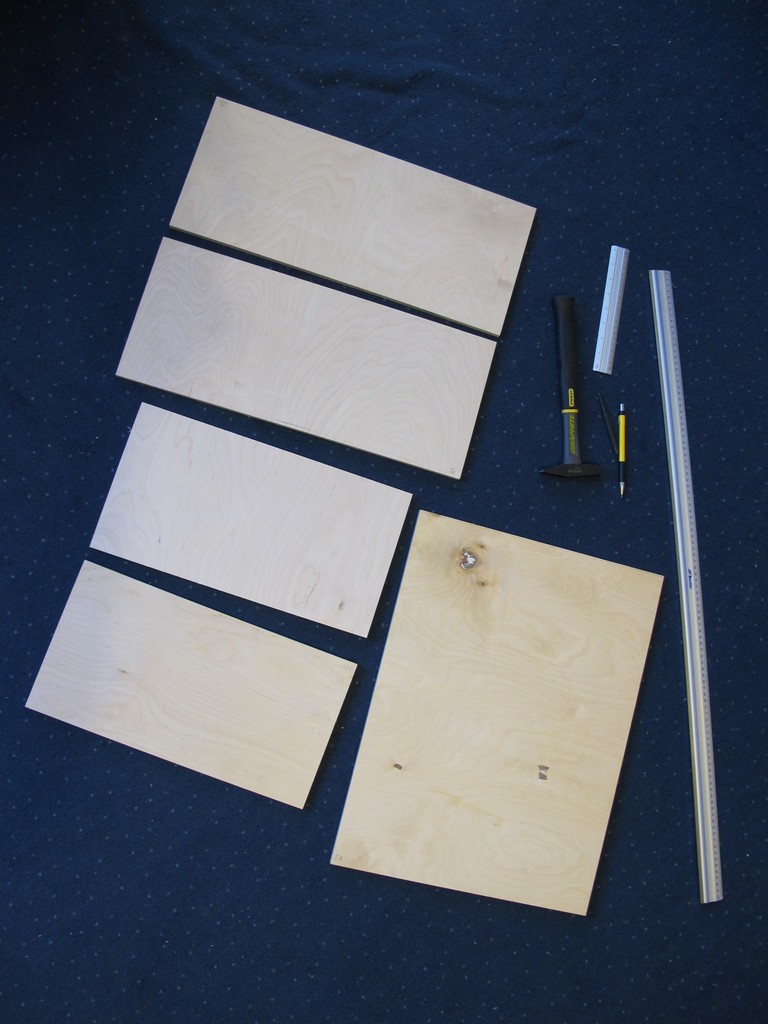
So, the first step was to check all dimensions. They cut every single piece of plywood 4 mm to big! (so, somehow perfect). The good thing is, the “depth” dimention is not as I planned (should be 220 mm, is 224 mm), but still same for side and top panels – so the case will be 224 mm depth. The width and hight of the box will be a bigger problem (but not as big as I thought).
I looked at all pieces carefully and chosen “external” and “internal” wall of each plywood panel. Some (like the back piece) had big ugly fillings and knags and I didn’t want them to be visible. I put the box together “in the air” and marked internal top left corner of each panel with caption (LEFT, RIGHT, TOP, BOTTOM, BACK) to knew its position in a box. It is easy to make an error while drilling / glueing.
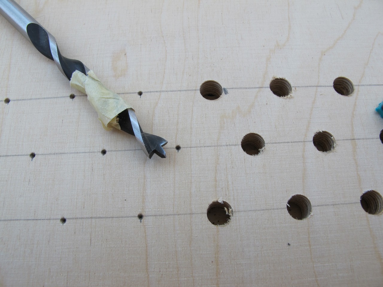
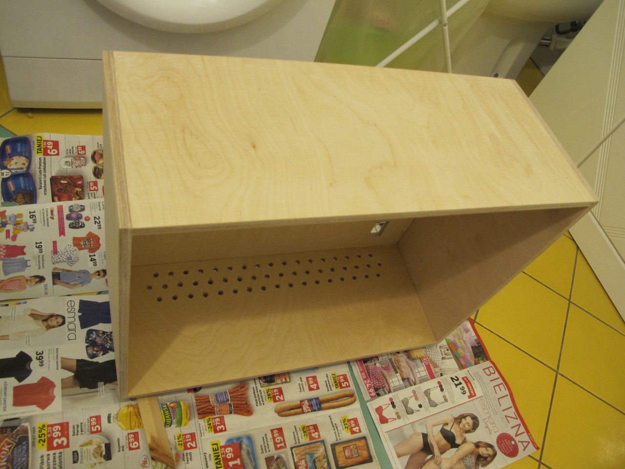
The first serious step was vent drilling. There are 104 of them – 52 on the BOTTOM wall and 52 on the top of BACK wall. The diameter is 8 mm (the largest wood drill I own). I used electric drill to make them. You can find different methods of drilling in plywood – some uses f. e. masking tape or drilling thru other wood piece. The best I found: highest rotation speed (1600 rpm for me), steady hand, moderate pressing force and drilling from the visible side (input of the drill is always very clean). Before drilling in my precious future case, I made about 20 holes in spare plywood piece to get correct force and movement. The results were quite good.
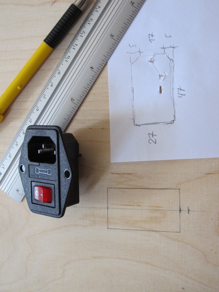
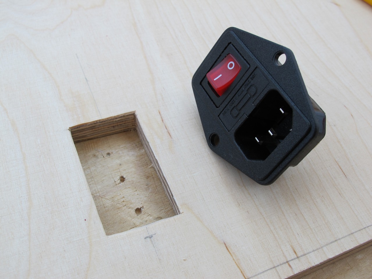
The next was to make hole for power supply socket. It is rectangle and requires some simple tools. First, I got the measures and marked hole position on the plywood.
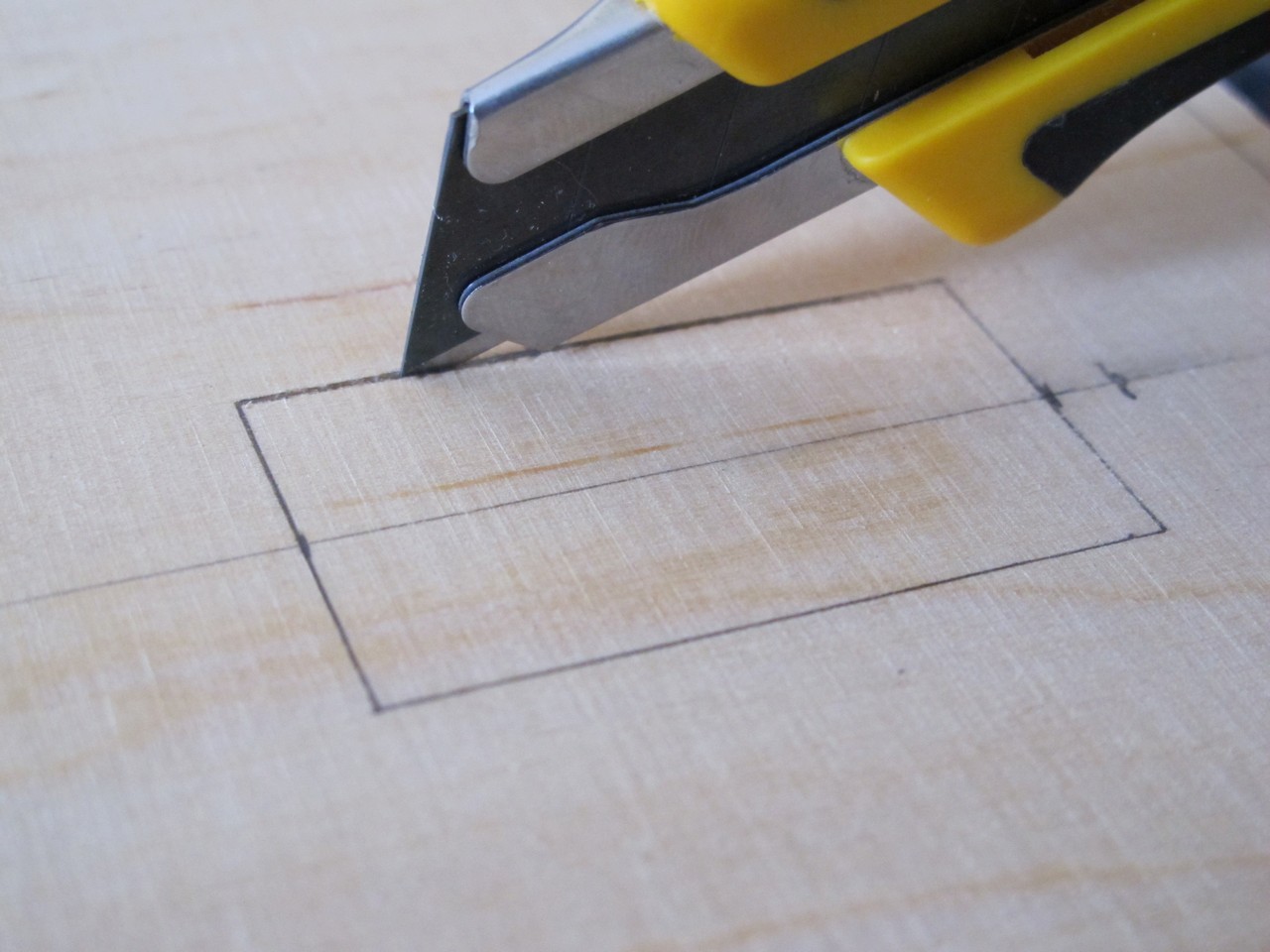
Plywood breaks easily. To get some control over it, I cut the first layer with the segment knife. The resulting groove also helps to guide the coping saw.
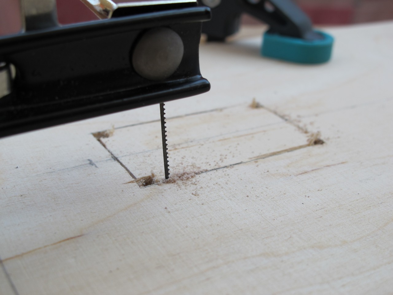
I drilled small holes in the corners to fit saws blade and start the cut. The PSU socket covers about 2 mm of each side of the hole, so it needn’t to be perfect (and it wasn’t :)).
Plywood piece came out easily. I grinded the hole with sand paper – whole module sits very tight inside. I secured it with screws later.
Glueing of the box
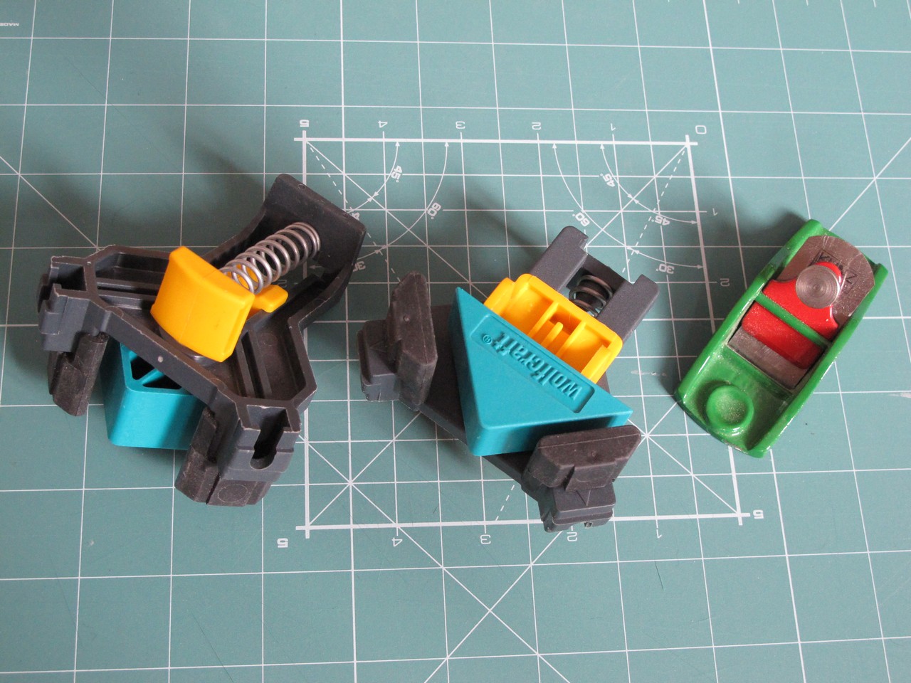
As I mentioned, all dimensions were 4 mm to big, so I had to get rid of 4 mm of 10 mm plywood. It is not an easy task without proper tools. Grinding, even with very coarse sand paper (P60) was very painful. After watching some YouTube videos, I bought myself a small plane. Corner clamps are very helpful, I borrowed them from a friend.
My girlfriend screamed when she saw what I did to my hands after a day of planing. I told her it is a modular synth case, it must be done.
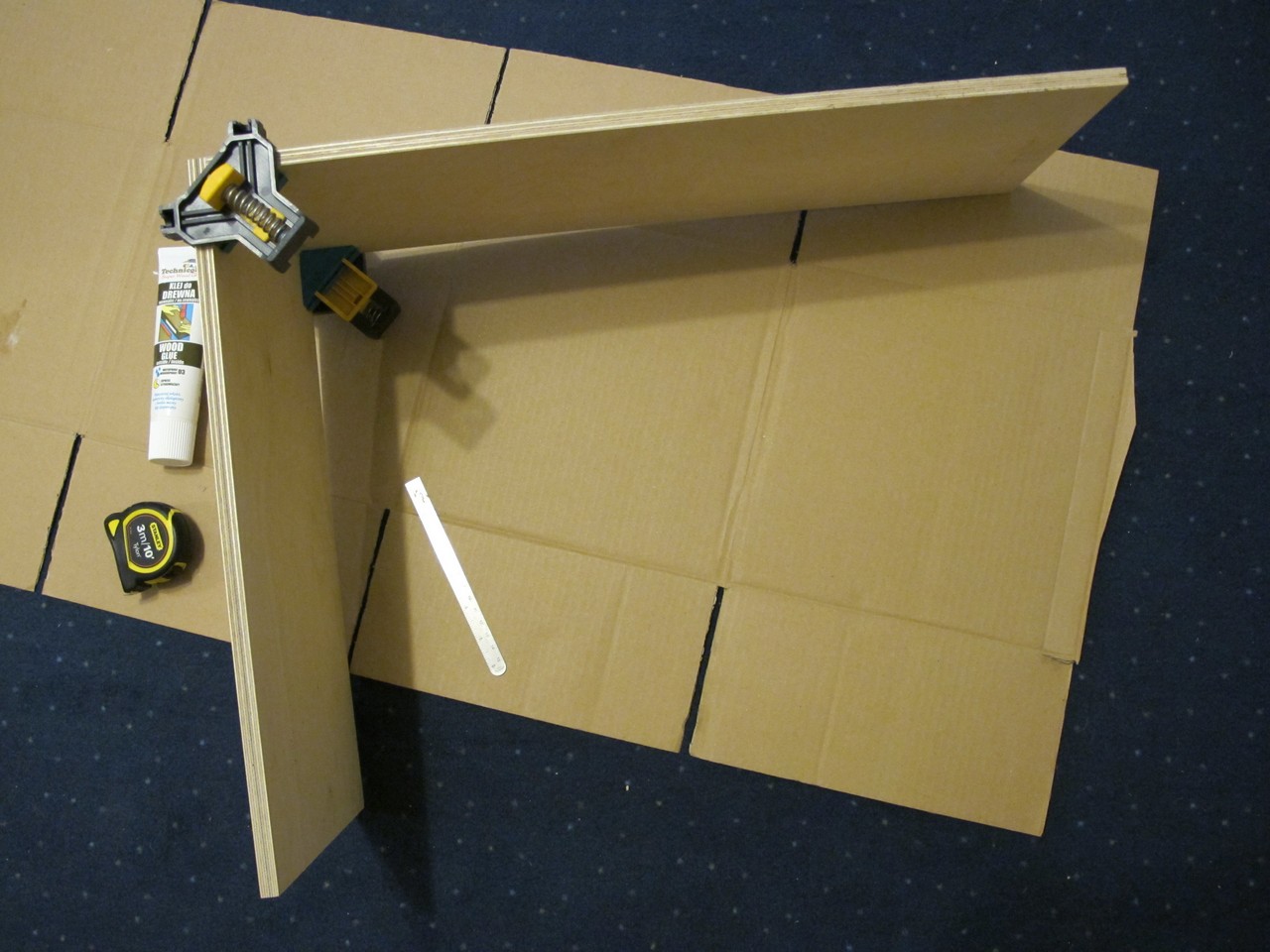
The BACK piece is crucial, while it determines hight and width of the final case. I cut it to exactly 529 x 395 mm. I also cut TOP and BOTTOM to 529 mm – they need to be exactly the same. After preparations I got to first glueing – TOP and LEFT. Corner clamps are really helpful – it is very important to keep exactly 90 degrees between panels – if not, the whole construction will be crooked. I used Technicqll Rapid 10 wood glue.
The next day I notice, it is not exact 90 (close, but not 90). It caused problems to the end, because on every following step I had to slightly bend the structure.

Tip: while the glue is drying, clean the excess if it immediately – I used cardboard piece. When it’s fully dry, it is much harder to remove, even with knife and sandpaper. I didn’t make it in the first step and I had a problem to glue the reinforcements correctly.
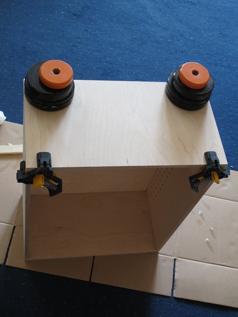
The box is taking shape. I used clamps, weights and tape to fix everhing while the glue dries. Because of lack of 90 degrees in the first step, I had to use excessive force to slightly bend the box to keep it straight.
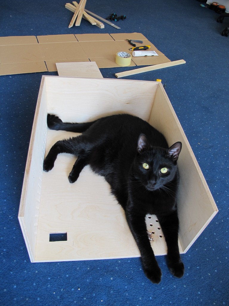
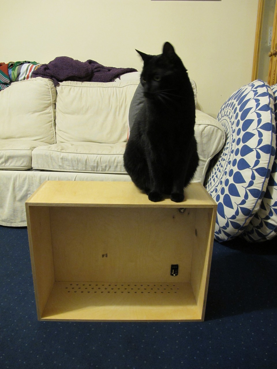
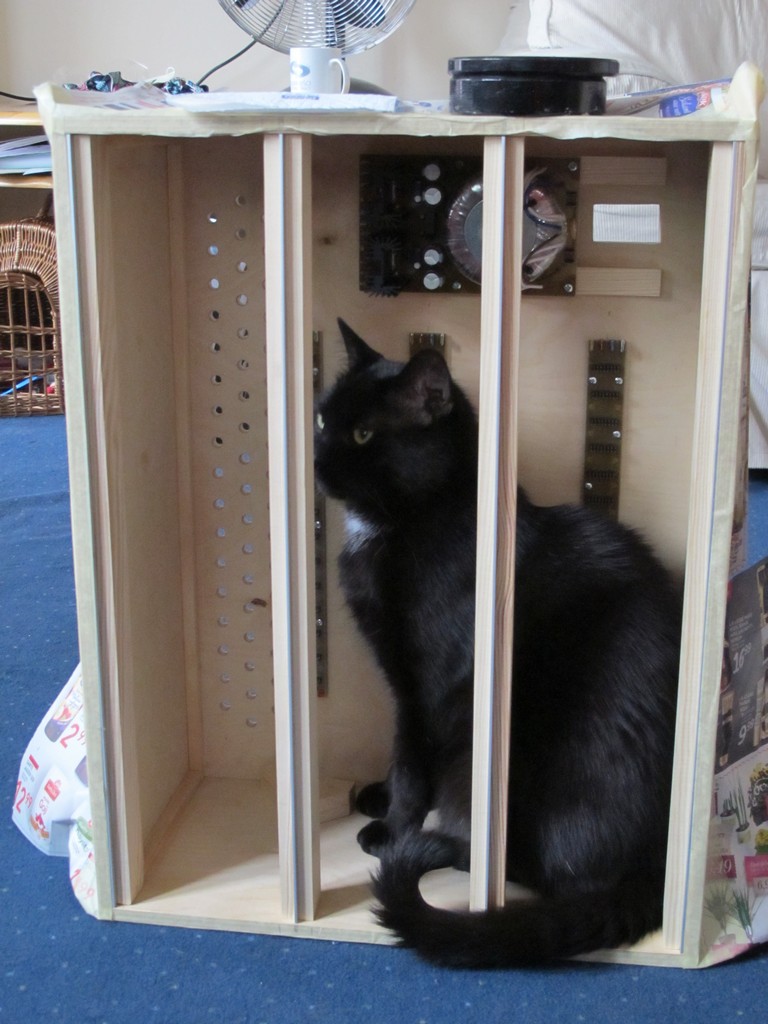
Quality control is very important. The earlier you see the error, it is easier to fix. My cat knows it. Time for the big final glueing step.
It came out really neat. The glue dries about ten hours, so I could do only two connections a day (one in the morning and one in the evening). Getting to this stage took me 2 days.
Painting
Now it’s time for painting. First, I grinded the box with P60, then P120 sand paper. I sanded so long until I coudn’t feel a connection between the panels under the finger. Don’t forget to clean all the dust with the vacuum cleaner. I skipped this step and it got into my girlfriends plants on the balcony. I had to run.
Before painting, I made two this little “devices” – made of leftover boards and two screws. Using them I was able to put the coating in one approach.
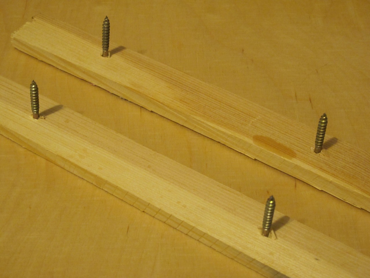
This is how it works:
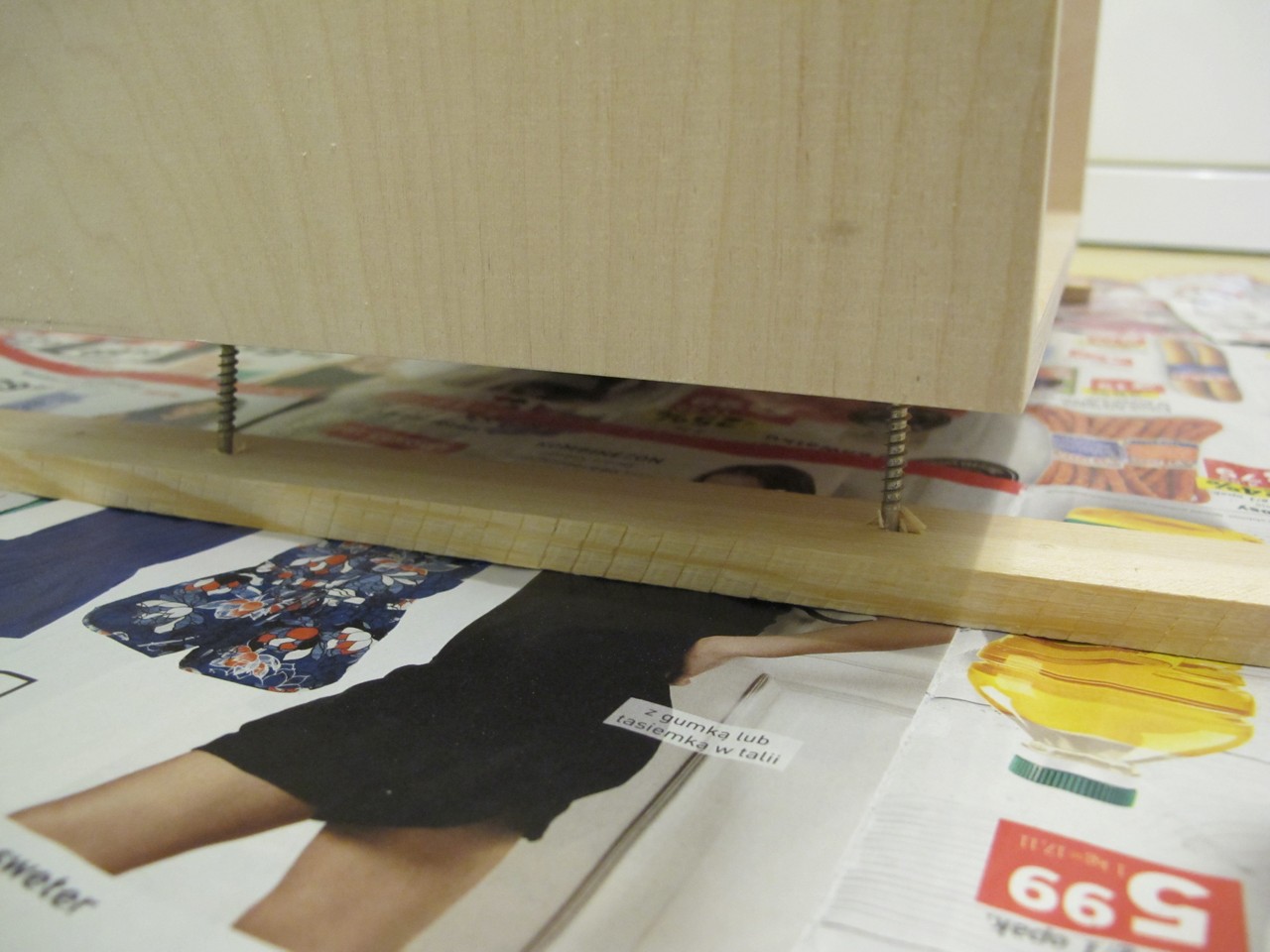
- put the box on the distances (tip of the screws) – they will made a little marks in the BOTTOM, but almost invisible,
- paint LEFT, RIGHT, TOP, BACK side,
- put the hand inside the box, pick it up, rotate (I can be done with one hand) and varnish the BOTTOM,
- ensure there are no bruises, it not, spread the excessive paint with brush,
- put the BOTTOM side on distances again.
I put 4 layers of Syntilor Aquarethane Matte varnish. Each layer (except last) was sanded with P240 paper to get rid of air bubbles, then cleaned with paper towel. I made a small error – I should have painted it also on the inside (I put varnish only about 10 cm from the edge, so all internal walls are almost uncovered).
The rails
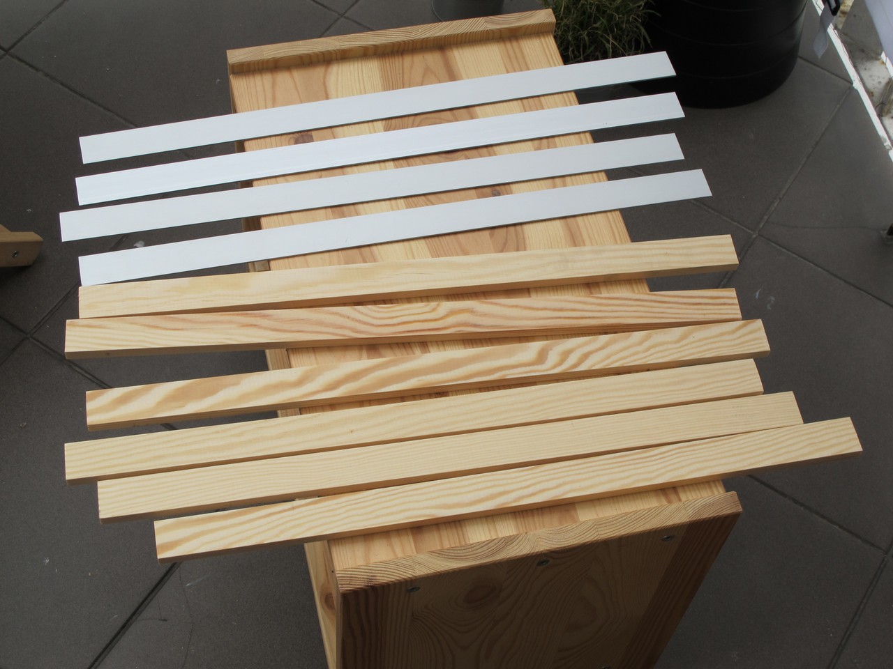
To make a rails, I used wood squared pine and anodized aluminium flat bars. I cut 10 sections in total:
- 6x (10 x 30 x 529 mm) pieces cut from squared pine,
- 4x (2 x 30 x 529 mm) pieces cut from anodized aluminium flat bars.
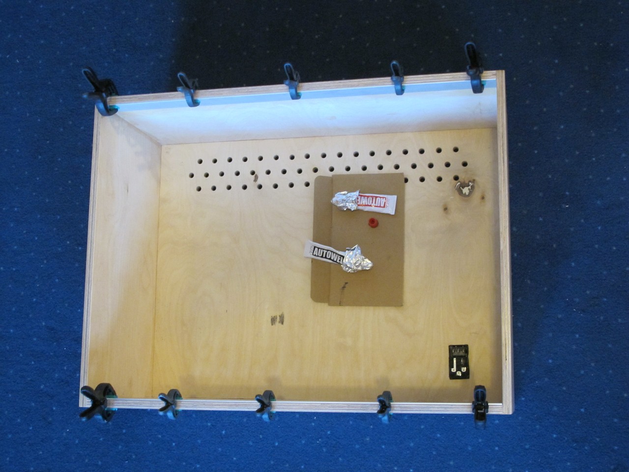
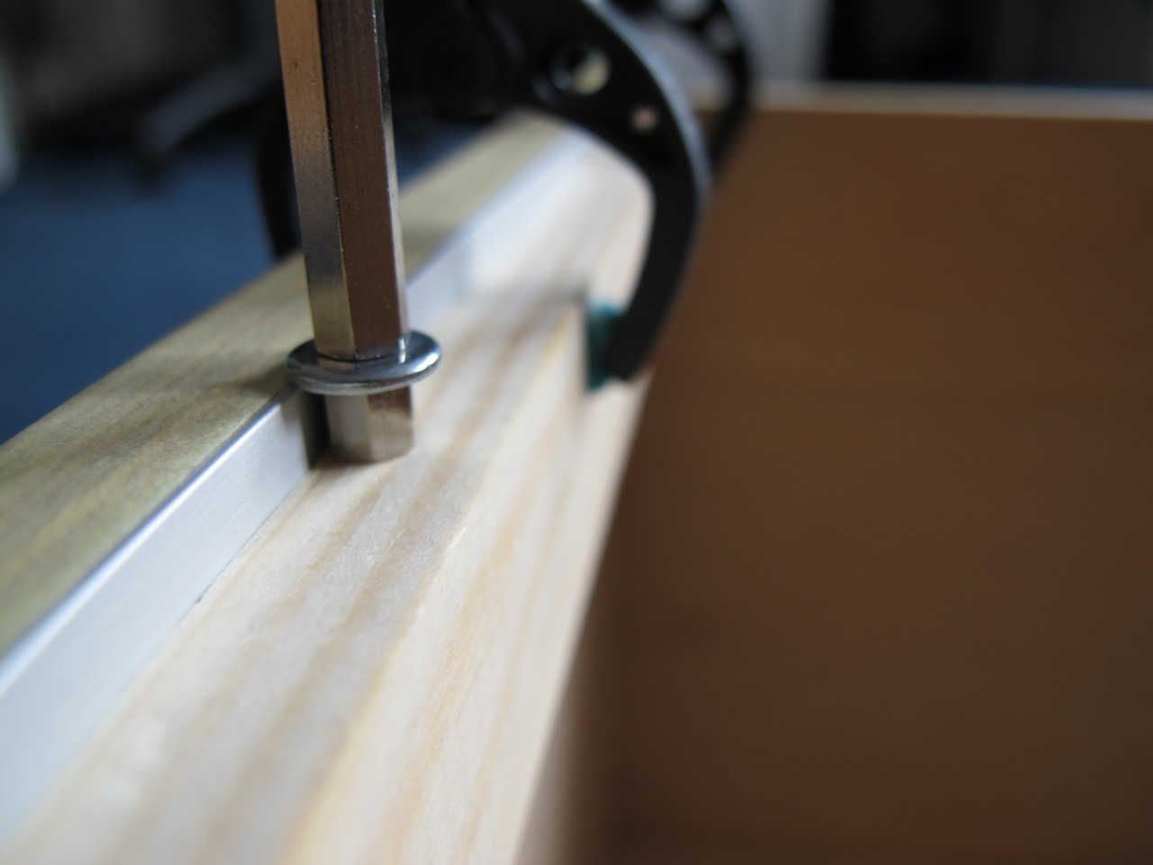
First, I glued aluminium bars to the wooden box with AutoWeld CX80 and fixed with clamps for about 10 hours. The trick is to put not to much glue, in other case it will flow on the front edge of the box – and it is very hard to clean. Remeber to degrease the metal!
To get even distance from the edge (5 mm) a made this small tool – 5 and 30 mm metal spacer with washer in between. This greatly improved the repeated measuring process.
Meantime I decided it is a good idea to protect the sides with paper. Without it, the box is easy to dirty with glue. It is already in cats fur.
This is a good moment to add the reinforcements on the internal edges. With middle rails installed, the access will be limited. Reinforcements are made of 10 x 10 mm squared pine. I just took fast measurements and fit them inside. They perform two tasks:
- strenghten the connection between TOP side and LEFT / RIGHT / BACK – with handle installed, it has to withstand the weight of a case, PSU and modules,
- strenghten the aluminum / wood connection of the top and bottom rail.
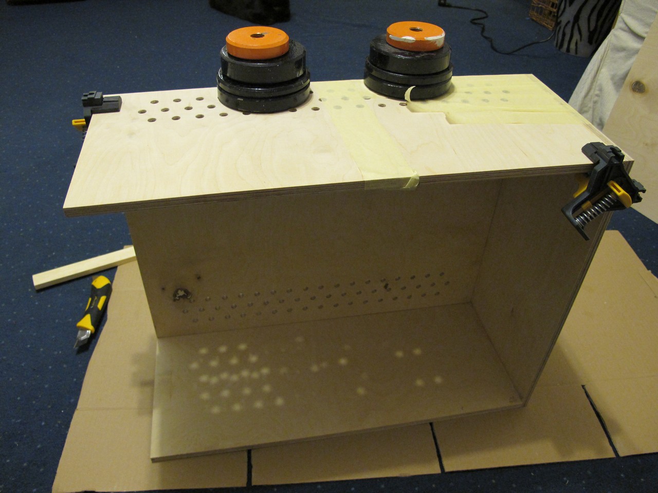
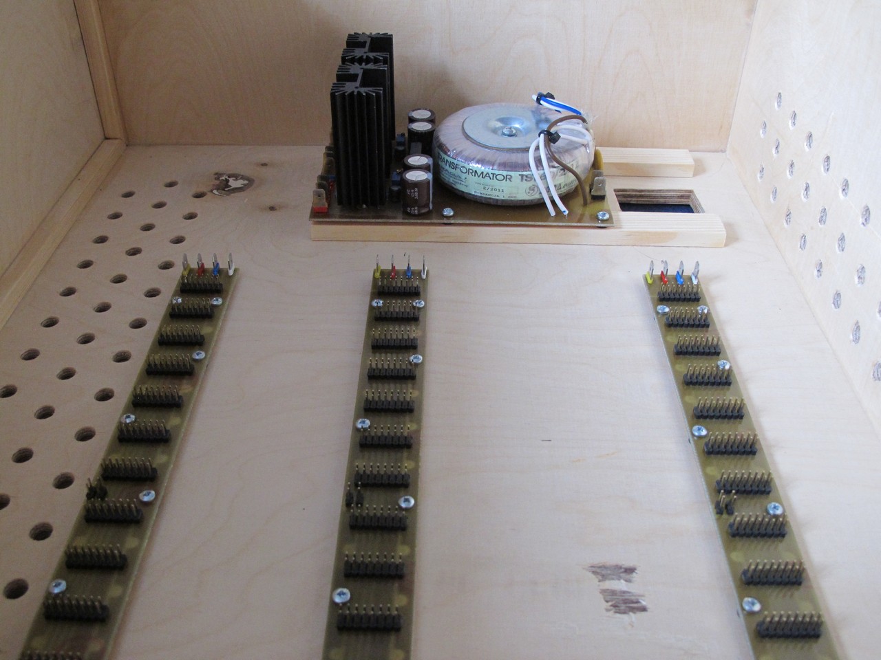
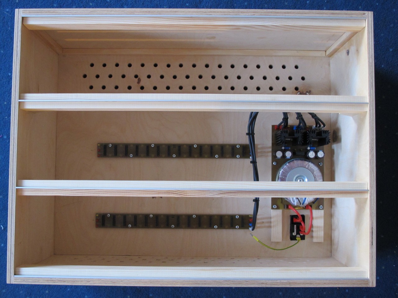
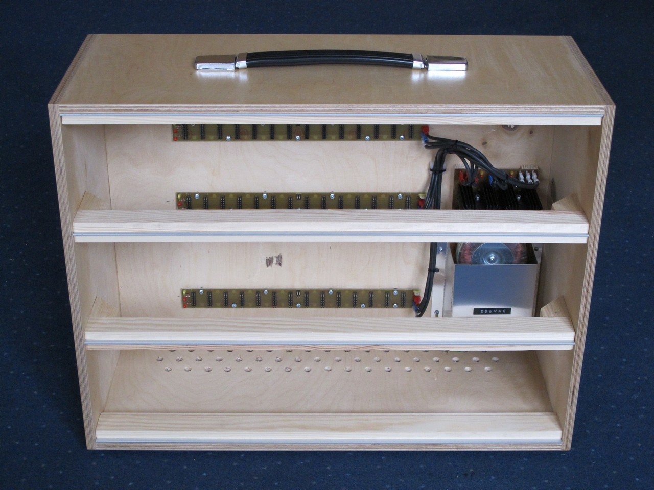
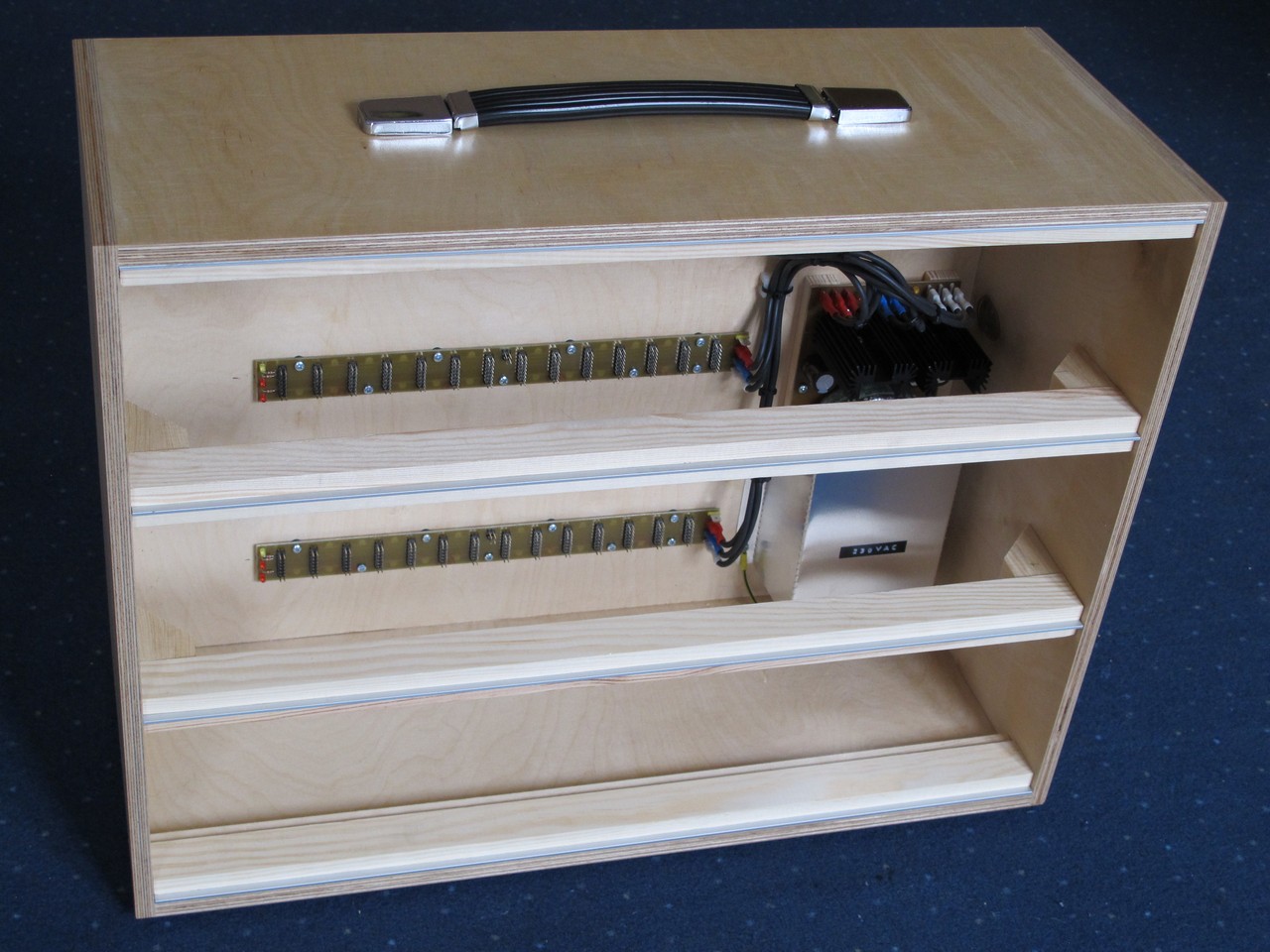
When middle rails are still not there, it is time to install PSU and busboard. I have added some wooden spacers under the power supply – it is quite heavy and needs long screws to stay in place. The plywood is only 10 mm and I didn’t want to go thru it like Doepfer did.
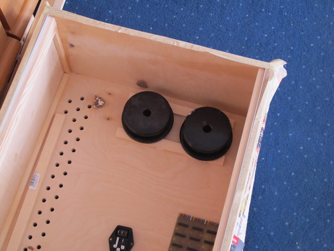
I had installed the PSU and busboards I built earlier. I used 20 mm screws for PSU and 10 mm for busboards. Later I will install protective cover over mains part of the circuit.
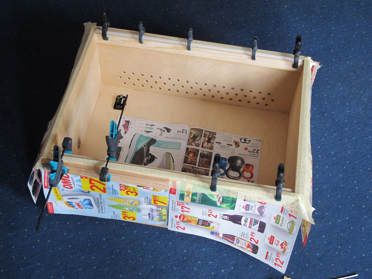
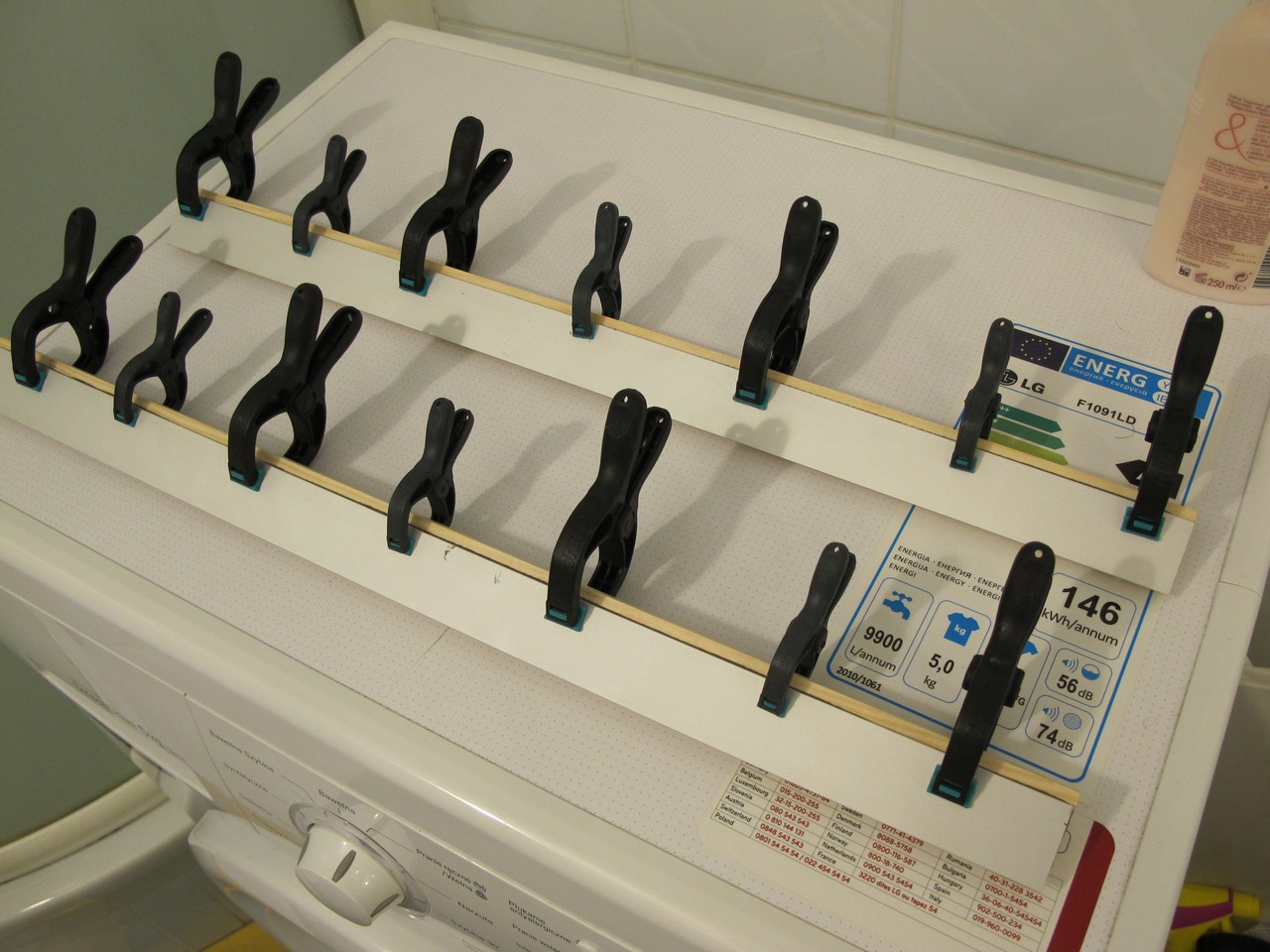
Time to make middle rails – I also used 5 mm spacer tool here. Taking the opportunity that my girlfriend was at work, I use washing machine as a workbench. Remember, the wooden pieces have to be perfectly straight to keep 129 mm distance all along between rails.
Before fixing middle rails to box, I marked its positions on the edge (you can notice pencil marks). Space between aluminium inserts is equal to 129 mm. I took a lot of measurements here to ensure everything is fine and moved some blank euro panel up and down to check the distance one more time. I put weight on top to make shure the connections will be strong. The cat is there because he wants to.
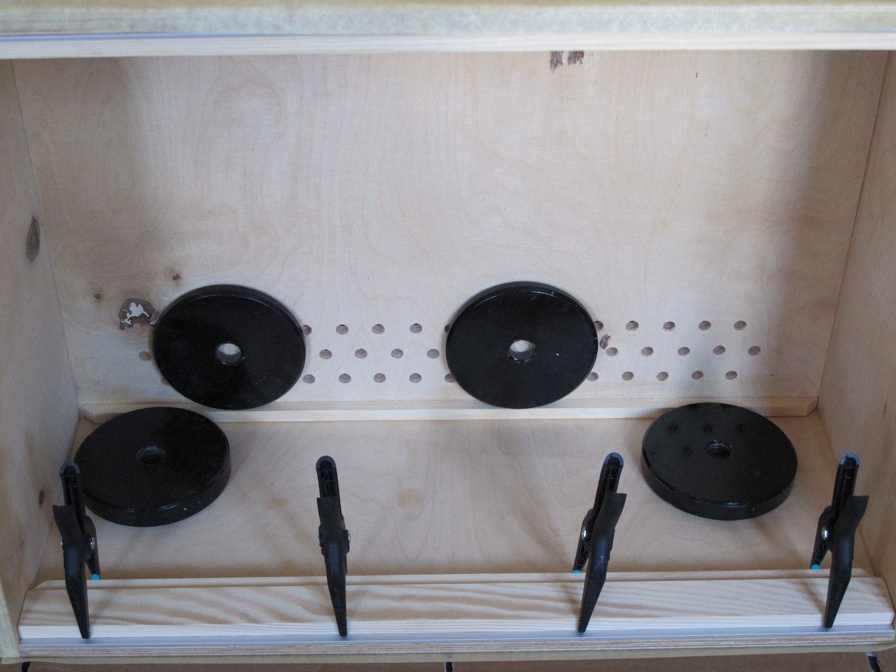
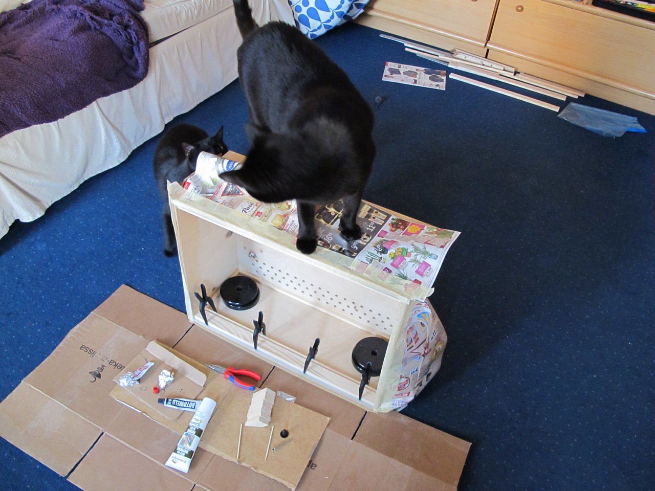
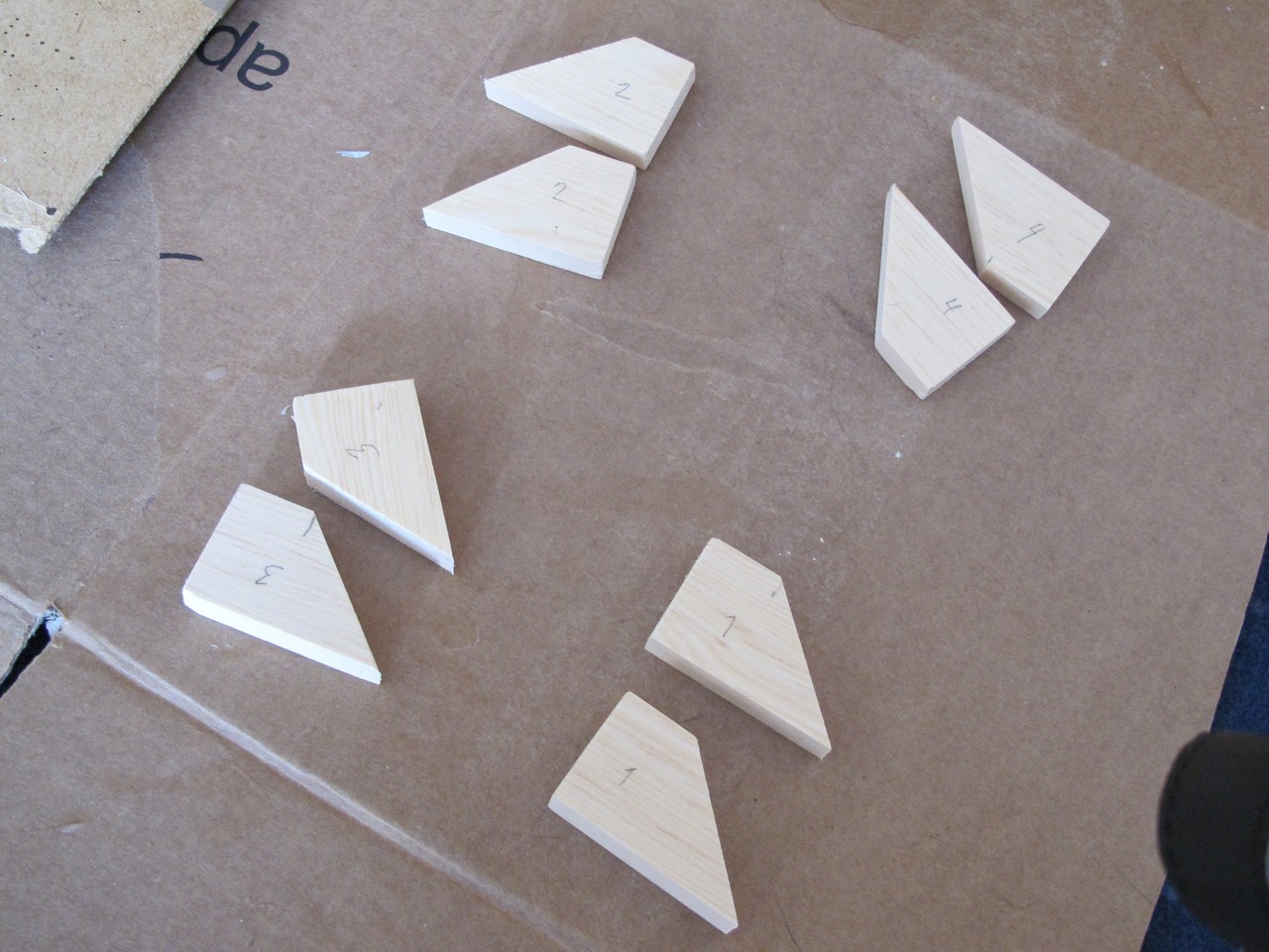
But it’s not over. The surface of connection between middle rail and a box is only 6 cm2. I decided to add more reinforcements to keep rails on place when panels will be screwed to them. I used leftovers from 10 x 30 mm squared pine to cut somehow triangle-like shapes, then glued them together in pairs to get 4x 20 mm thick pieces.
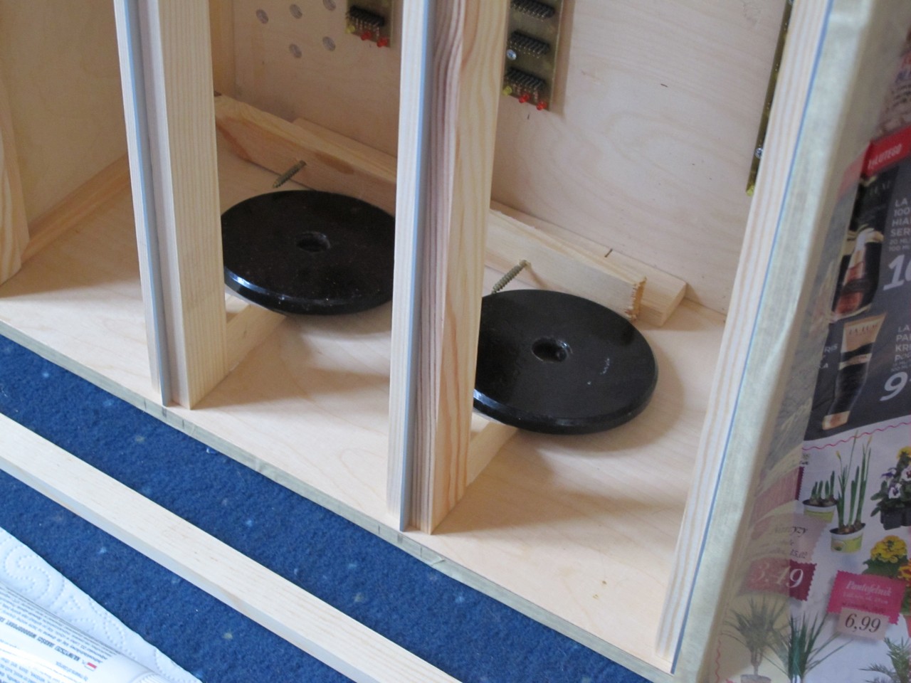
Then I used weights to fix reinforcements in place, two on each side. The rails are connected so strong, you can raise whole case with one hand holding one of them. The last thing is to fasten the handle and rubber legs.
Finish!
At the end I’ve added handle (Adam Hall 4900) and rubber legs (Adam Hall 4900).
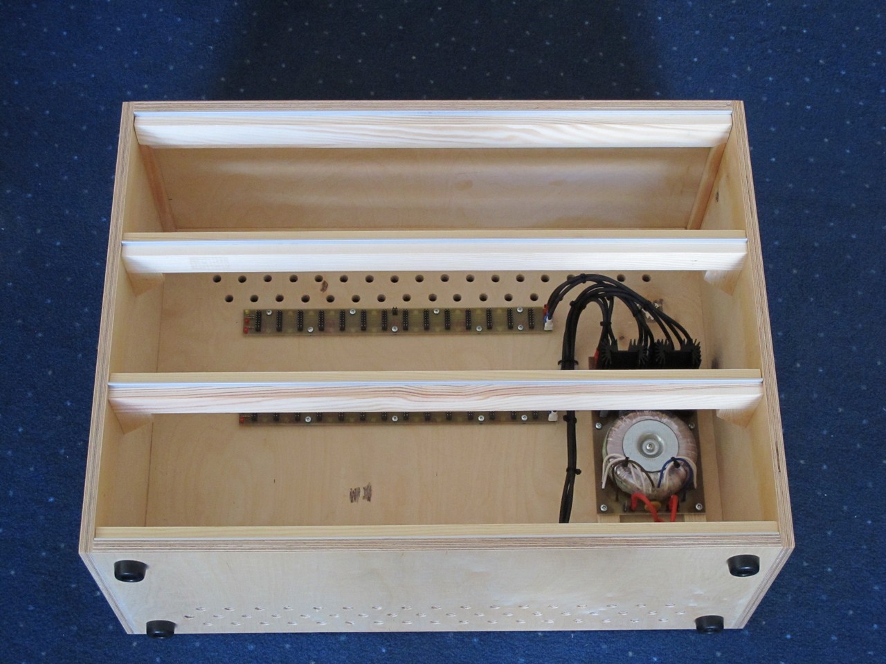
Later I’ve installed cover for PSU 230 VAC section. It is connected to protective earth (PE).
Summary
The estimate cost of the project:
- hardwood plywood wth cutting – 10 euro,
- squared pines – 6 euro,
- aluminium flat bars – 8 euro,
- handle (Adam Hall 3419) – 7 euro,
- rubber legs (4x Adam Hall 4900) – 1 euro,
- acrylic varnish (Syntilor Aquarethane Matte, 0.25L) – 7 euro,
- wood glue – Technicqll Rapid 10 – 2 euro,
- universal glue – AutoWeld CX80 – 4 euro,
- sand paper (P60, P120, P240) – 3 euro.
Total: about 50 euro, but you will not use all the glue and varnish for shure. With PSU and busboards, it will get closer to 90 euro.
No cats were harmed durning woodworking.
Cheers
Exhausted Jack
It took me 14 hours to write this post.
killin’ man…
14 hours well spent on this post (not to mention days worth of time making the case). Inspiring and very helpful!
I’m very glad it was helpful!
your website is incredible, many thanks to share your work with the diy makers!!!!!!
Thanks, I try to do my best. I took a lot from other people, now its time to give something in return 🙂
thanks for the great writeup (as usual. 😉 ). i am gonna adapt some ideas of yours to fit my diy case. found a big plastic cd case in black wood look taking two rows of modules in height almost perfectly. 🙂
I’m very glad it helped! I know, the enclosure is not perfect and it can be improved :/ Cheers!