I was making synths and stuff, while my girlfriend played on Youtube a Manu Chao live performance. I noticed some familar sounds I knew from my childhood – the Executor keychain, true classic (there is also an Android app thats imitates it).
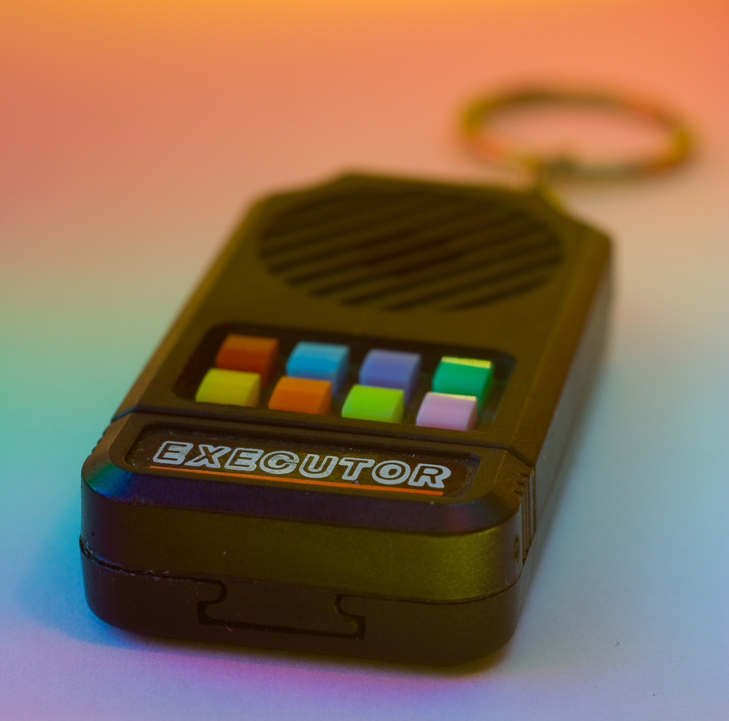
I made some research and I found a specialized, proffesional device destined for this kind of lo-fi, arcade-like sounds: the dub siren. The set of sounds from Rigsmith was very similar to Executor, so there sould be an avaliable IC that makes all the work. On Aliexpress I found a small kit called
Before I touched the soldering iron, I looked at original Executor waveforms and read the specs of IC from NES game console as additional inspiration.
So, what have I done? I finished with somehow strange device, something between advanced digital dub siren and drum module with modular synth connectivity.
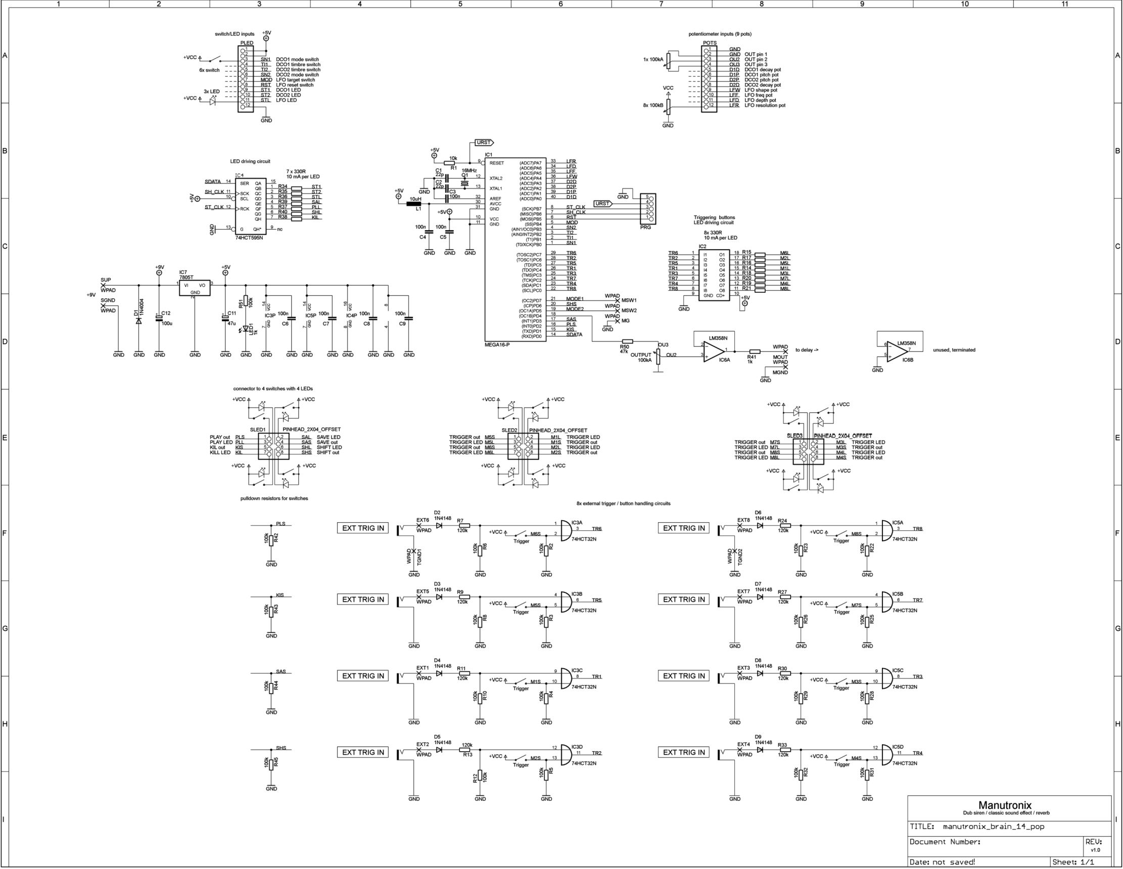
The circuit
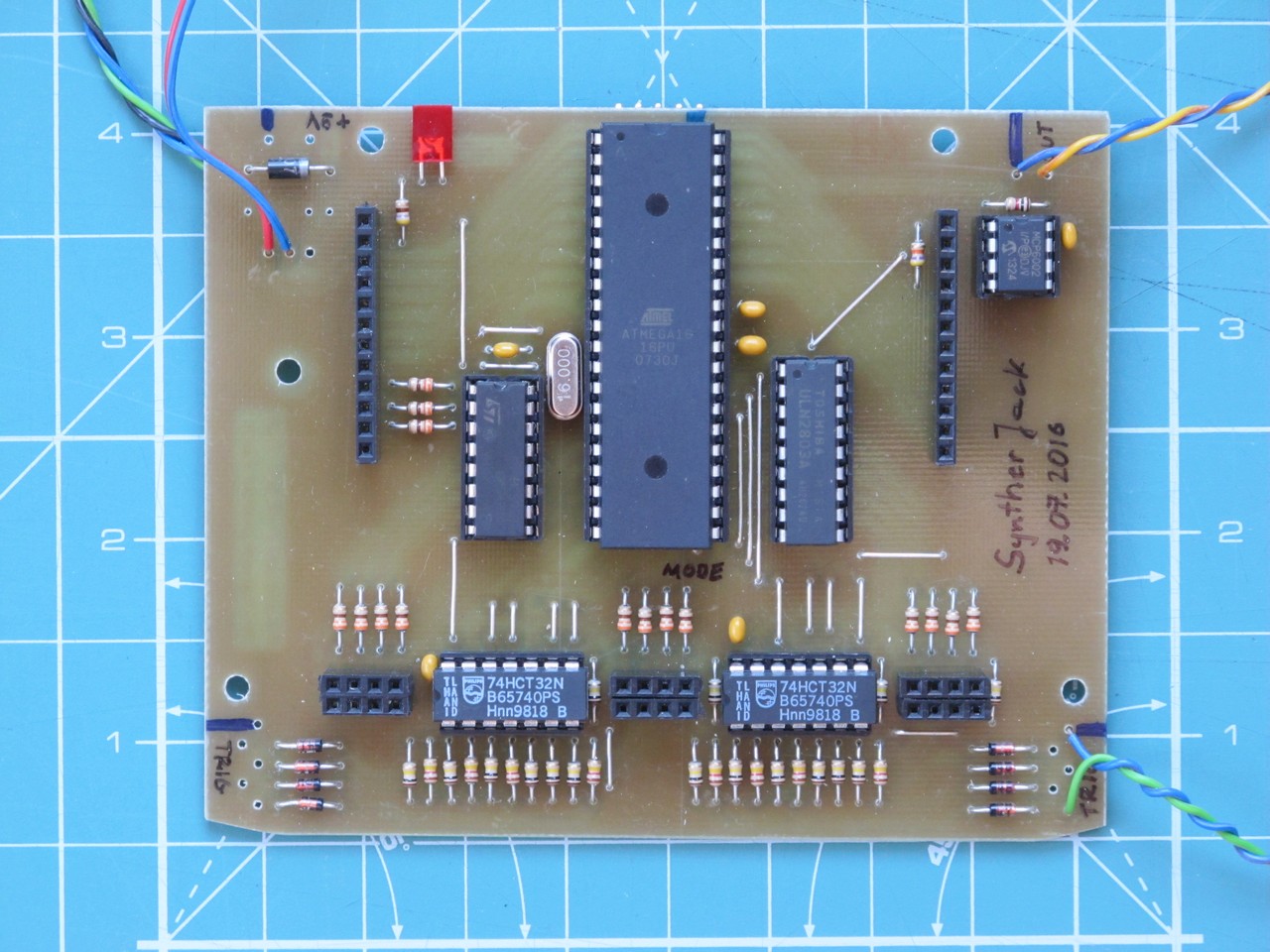
The device is based on Atmel Atmega16A running at 16 MHz. The microcontroller is responsible for:
- sound synthesis,
- reading all pots positions via ADC,
- reading state of all buttons,
- handling the (it drives LEDs).
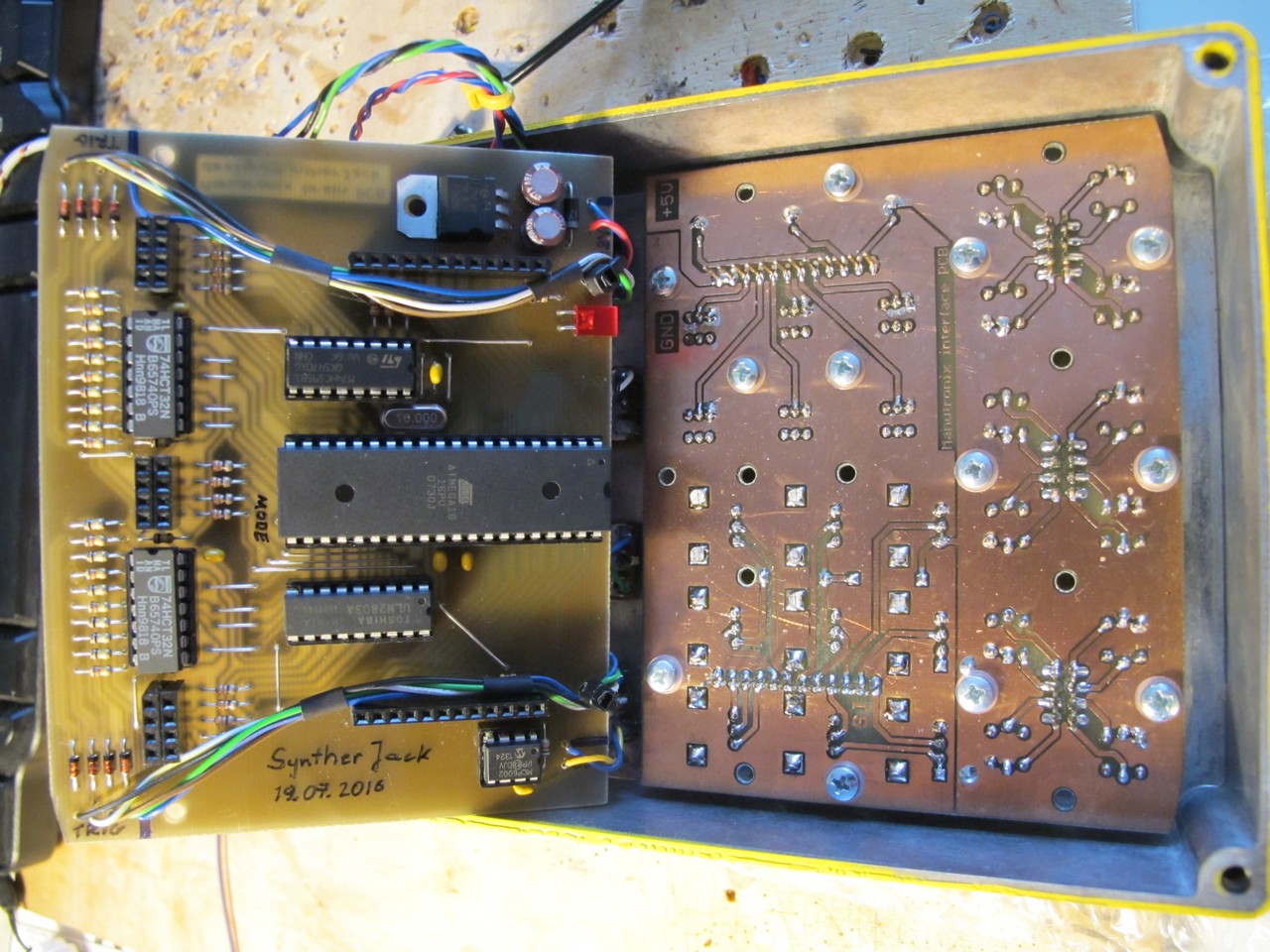
74HCT32 sums the external trigger signal and button value that finally reaches microcontrollers pin. ULN2803 is responsible for driving trigger buttons LEDs. The output is buffered via opamp. The circuit is divided into 2 PCBs.
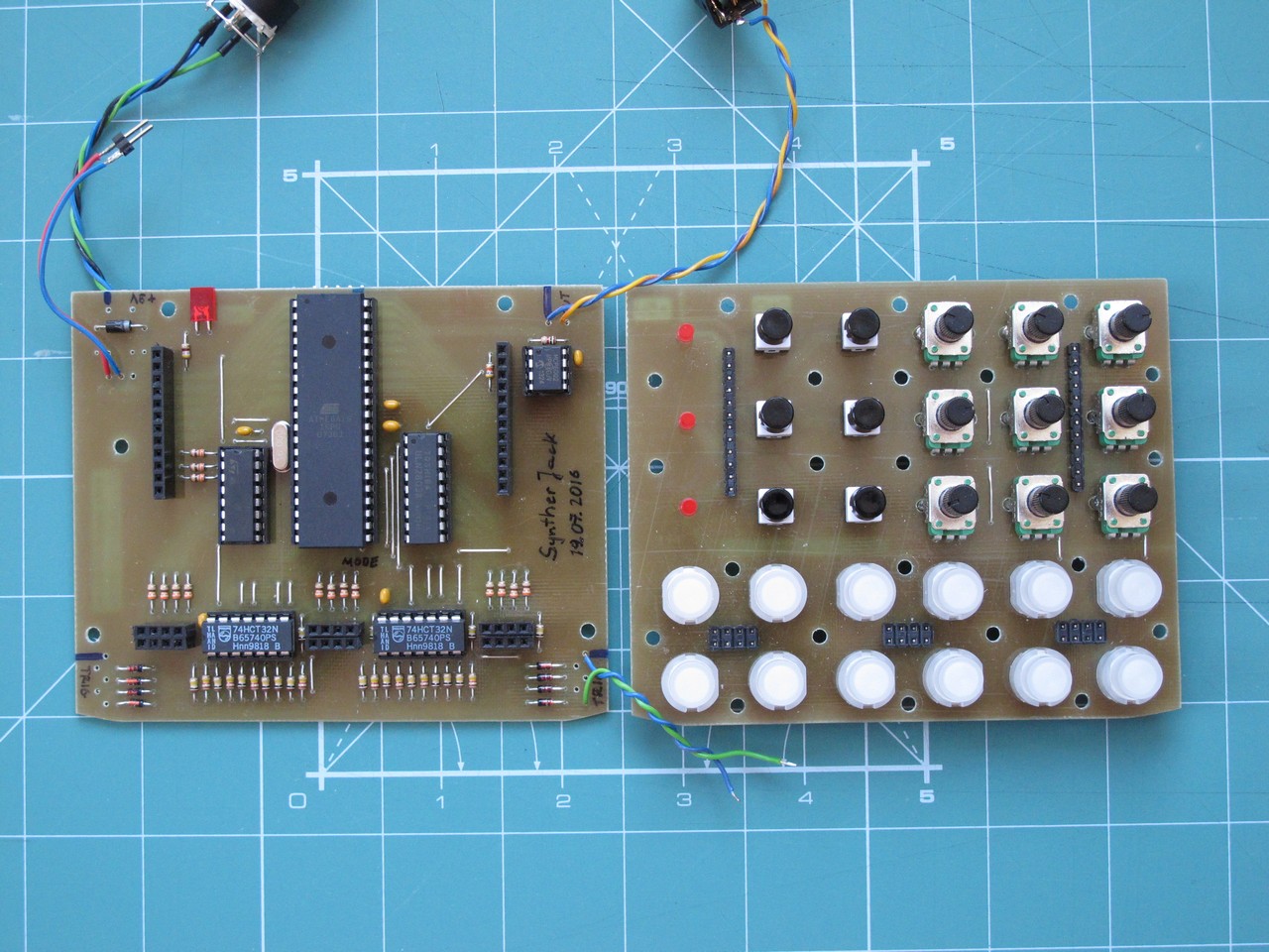
I made a partial prototype on breadboard. There are many repetitive parts of the circuit, so I checked only if idea is ok. Making a full prototype would be very painful – too much pots and switches. I have divided the circuit into 2 parts: “interface” (knobs, switches etc.) and “brain” (ICs). All PCBs were home made and I don’t like to make double-sided circuits, thus a lot of clamps.
The “interface” and “brain” PCBs are connected with 2,54 mm pin headers. The pots are Alpha Taiwan, switches with LEDs – Highly.
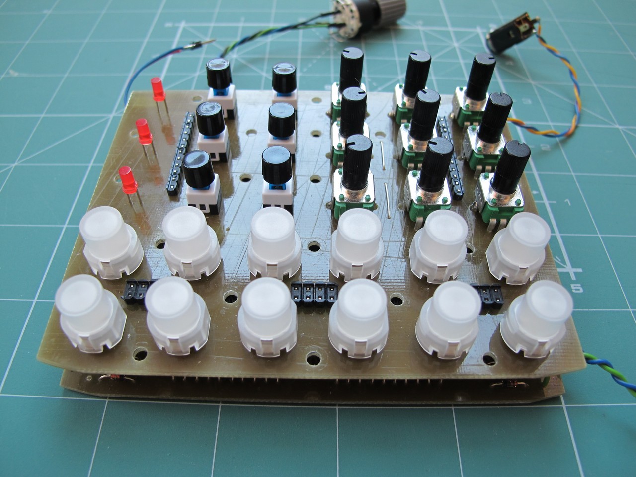
Both boards have the same size and fit together like a sandwitch. “Interface” PCB has a lot of holes to mount it to front panel, especially near the buttons – a lot of force can be applied here while jamming.
The tests went quite good, I didn’t make any significant errors – except lack of 4 pulldown resistors (but the schematics are fine).

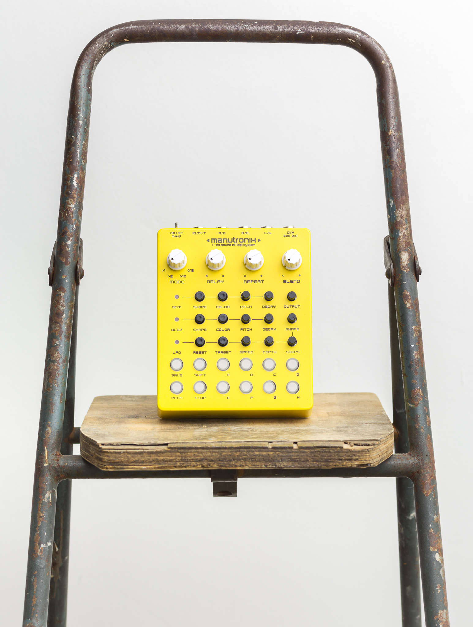
The enclosure
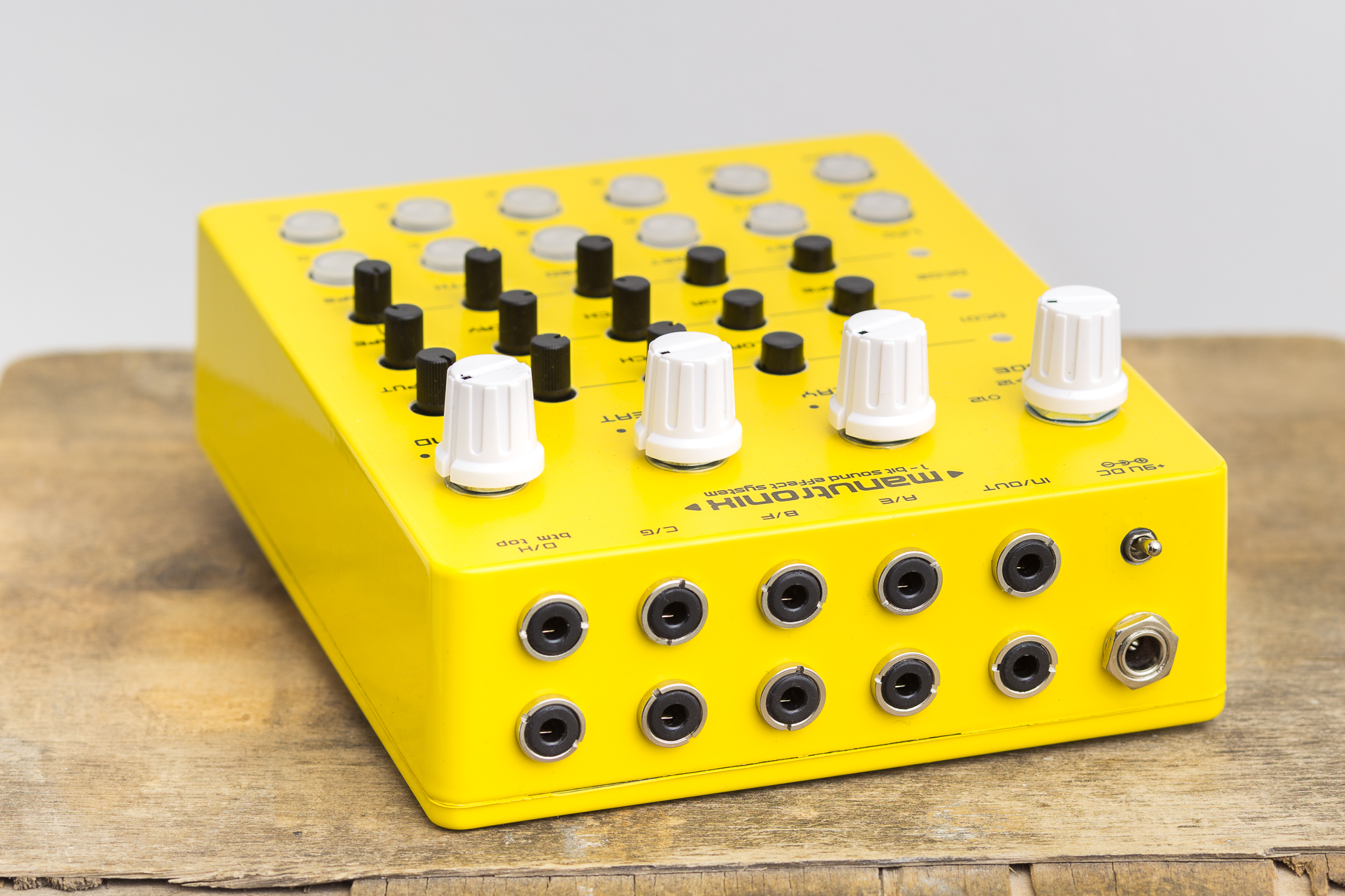
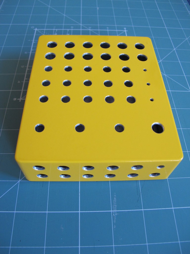
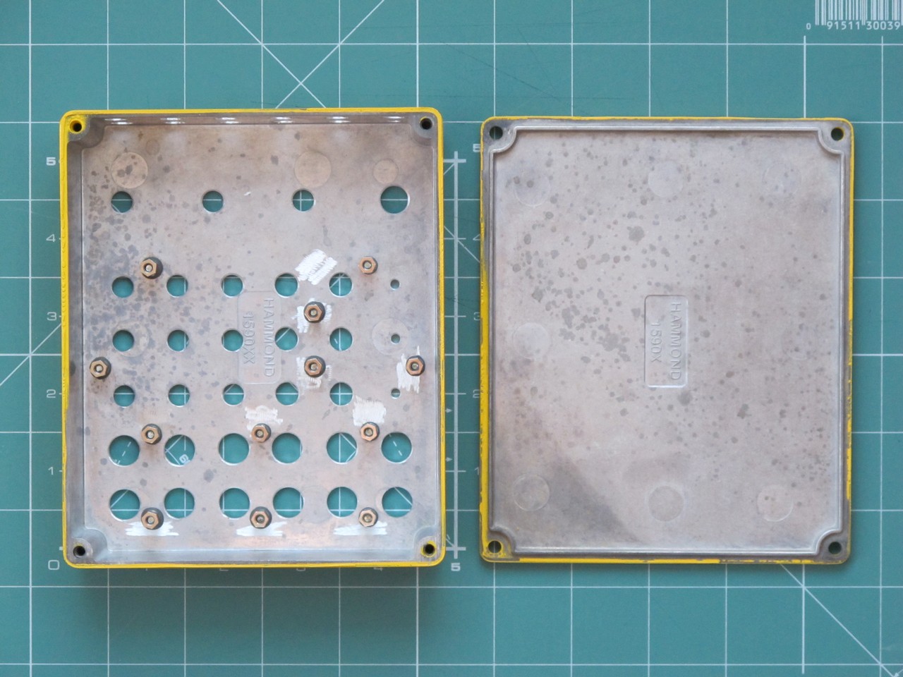
I have used very nice yellow Hammond 1590XXYL enclosure. The factory painting was very good and I had no problems while drilling.
Inside I have glued a metal spacers to hold the “interface” PCB with AutoWeld adhesive. Not all holes in PCB were used, but it is fixed very well.
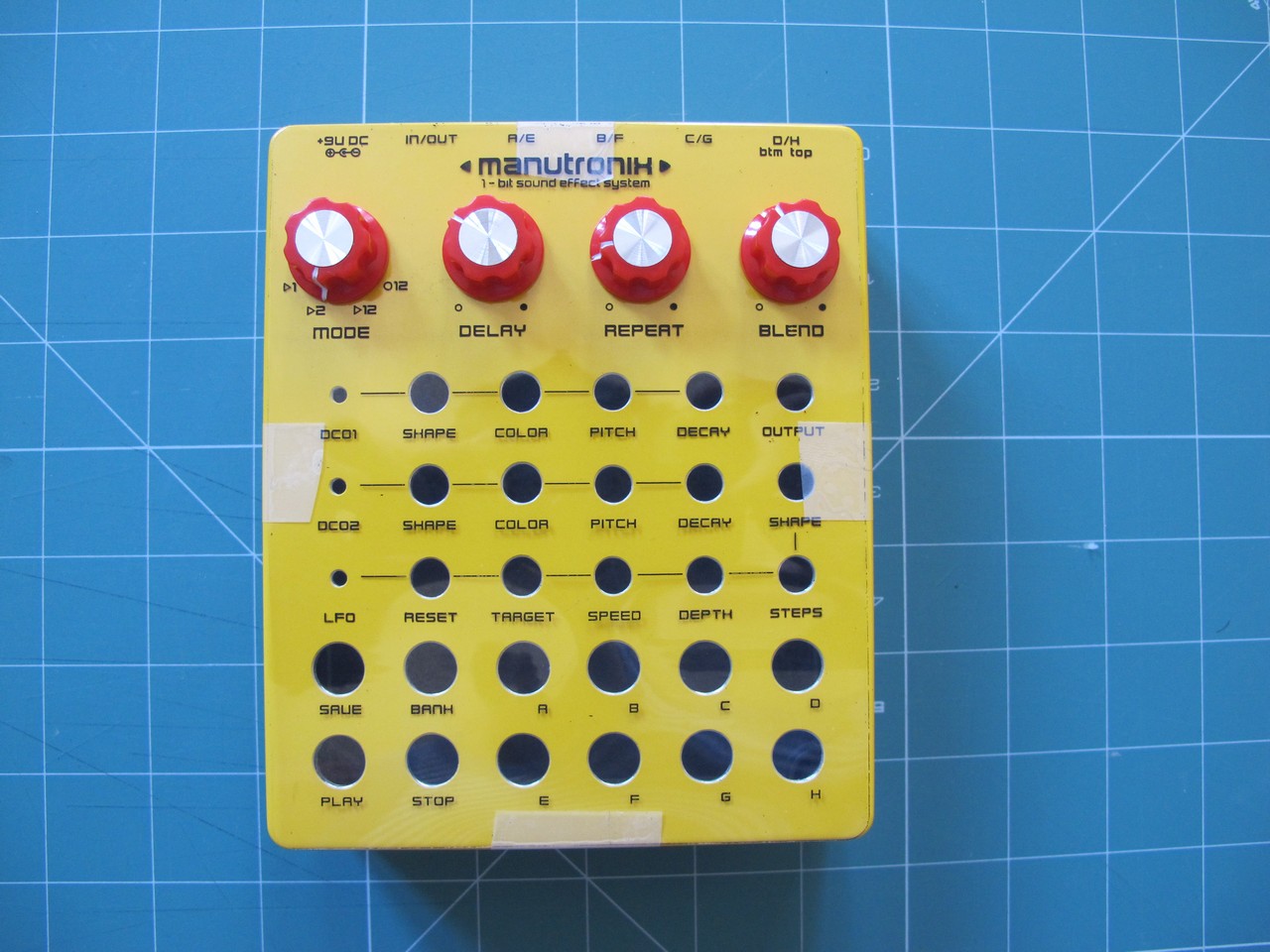
Later I made some test to choose the perfect knobs (those below were definitely not good enough). I also printed the front panel design to test if everything is clear and no text in covered by knobs.
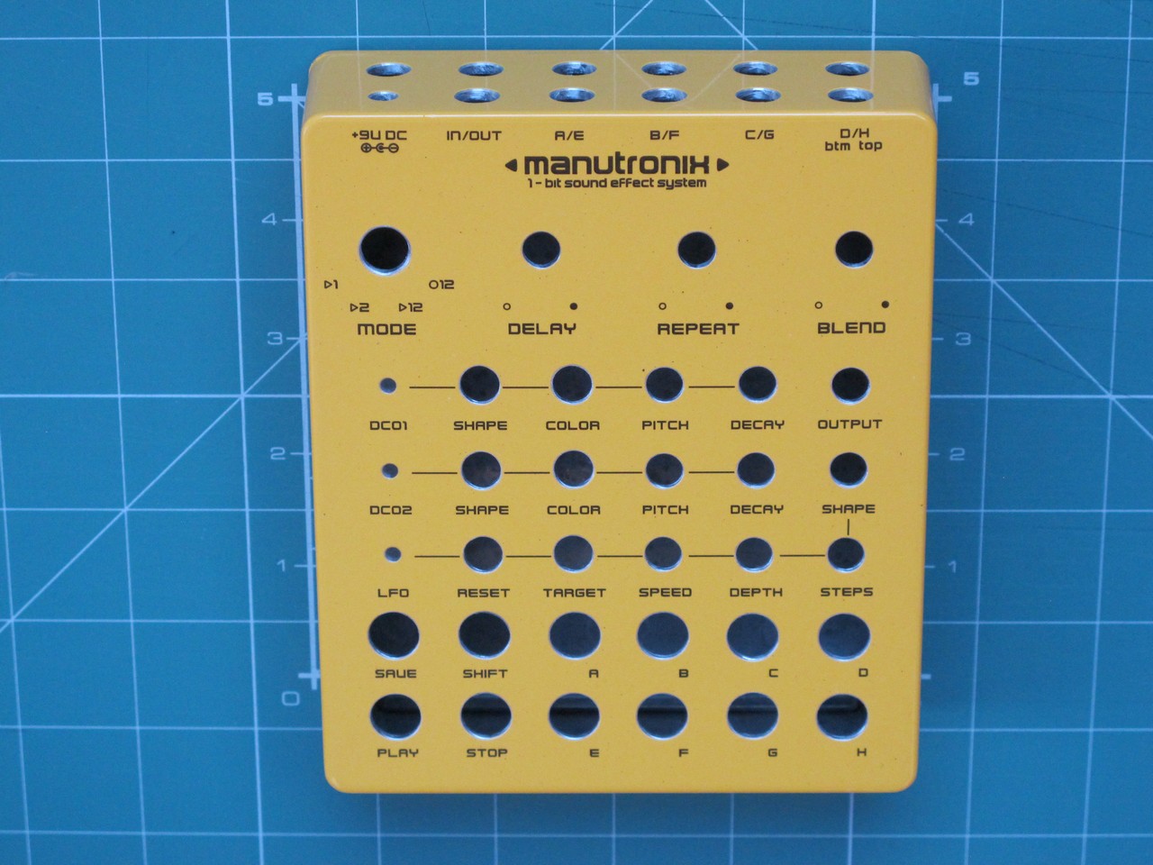
Then, at last, I put a water decal on the front and secure it with transparent acrylic paint, then fixed it in an oven (~175 Celsius). The enclosure was ready.
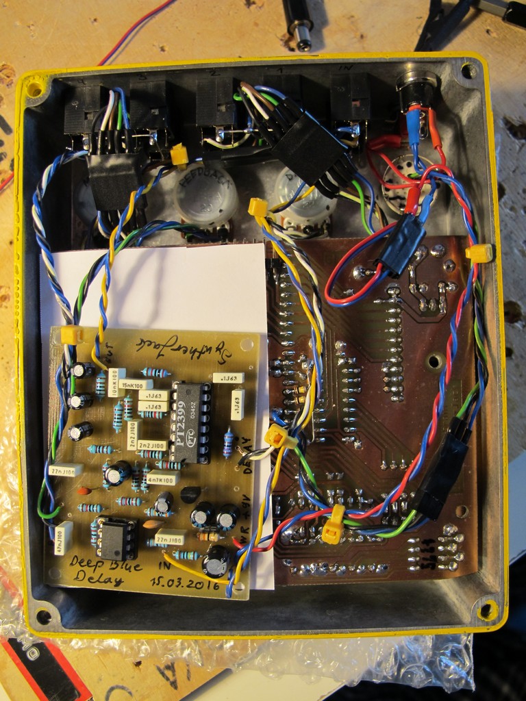
Only the “interface” board is screwed to enclosure, the “brain” holds only on pin headers, I made a stupid mistake and placed external trigger pads on the wrong side of PCB – I had to add long wires to connect them to jacks :/ Small LED on “brain” PCB indicates the presence of power supply.
All 3 PCBs (with delay) fitted almost perfectly. Wiring is a little tight and I had some problems to close the enclosure. There are additional connectors near jack sockets, so I could remove a PCBs for troubleshooting without soldering.
The synth engine
As I said, the sound generation is 100% digital, with 1-bit output (common for all generators). The engine uses: squarewave generator, noise generator and low frequency generator – quite simple structure.
Squarewave generator:
- frequency range – 0,5 – 2,5 kHz (it was defined by recorded then measured Executor waveforms),
- pulse width 25 or 50% for arcade flavour (inspired by ),
- synthesis is based on system clock division (it uses only counters),
- sampling frequency od 16 MHz (system clock frequency).
Noise generator:
- based on LFSR (Linear Feedback Shift Register),
- variable register lenght – 8 or 16 bits,
- clock frequency – 630 Hz to 80 kHz.
Low frequency oscillator (LFO):
- modulates squarewave generator pitch or LFSR clock frequency,
- waveforms – positive sawtooth, negative sawtooth and 13 triangle-like between them (total 15 generated waveforms),
- frequency range – 0,25 to 15 Hz,
- variable resolution of the waveform – from 8 to 1 bit (32 levels in total) – using this function you can make square from triangle waveform,
- phase reset option,
- DDS synthesis based.
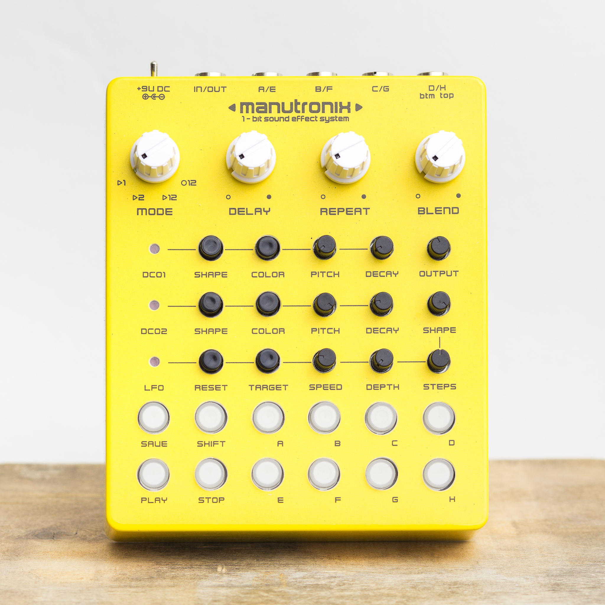
The user interface
It is not WYSWIG and can be a little hard to understand. In general, there are three main sections:
- decay settings (big knobs) – parameters of the Sea Urchin delay,
- synth engine control (all black elements) – you can create a unique sound (and save it later),
- memory / trigger buttons (all white / milky elements).
Each sound can contain 1 or 2 stages (for example: 1 second of squarewave – I stage, then 0,5 second of noise – II stage). Stages, marked on front panel as DCO1 and DCO2 can be loaded in one-shot mode, in series or looped.
All controls are described below in details .
- first row (white, big knobs):
- MODE control switch (explained later)
- DELAY, REPEAT, BLEND – build-in delay settings.
- second and third row have common elements connected with thin line – they are responsible for squarewave and noise settings for preset 1 and 2:
- DCOx – LED indicates, which setting is loaded,
- SHAPE – noise or square,
- COLOR – 8, 16 bit LFSR for noise and 25, 50% PW for squarewave,
- PITCH – noise / square pitch,
- DECAY – for how long setting should be played
- fourth row – LFO settings:
- LFO – LED indicates, if LFO is working,
- RESET – reset LFO waveform phase if sound playback is triggered,
- TARGET – preset 1 (marked as DCO1 on front panel) or preset 1+2,
- SPEED – LFO waveform generation speed,
- DEPTH – LFO modulation depth,
- STEPS – resolution of the LFO waveform,
- SHAPE – generated waveform shape.
- buttons:
- SAVE, SHIFT – for memory handling,
- PLAY, STOP – sound playback,
- A-E – “load from memory and play” triggers.
There are 4 modes of sound playback, or in other words, how front panel interface is read by synth engine:
- MODE 1 – play only preset 1 (DCO1) for DECAY1 time, then stop,
- MODE 2 – play only preset 2 (DCO2) for DECAY2 time, then stop,
- MODE 3 – play preset 1 for DECAY1 time, then preset 2 for DECAY2 time, then stop,
- MODE 4 – play preset 1 for DECAY1 time, then preset 2 for DECAY2 time, then return to preset 1 etc (looped mode).
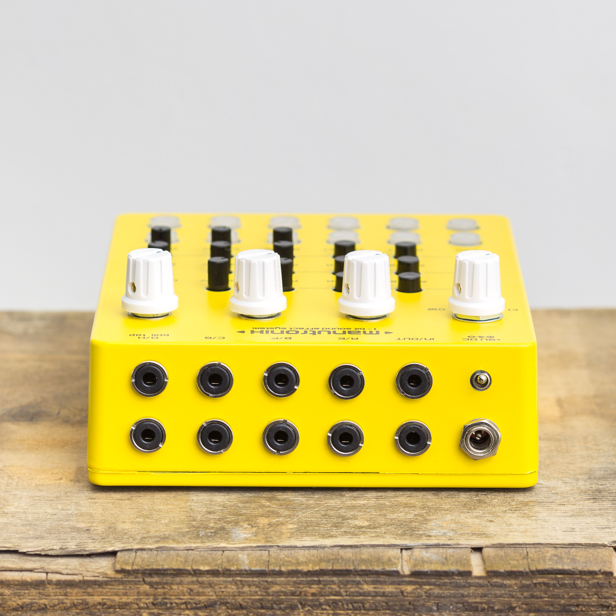
There are also mini jack connectors on the top of device – you can trigger saved sounds with f.e. Beatstep or modular system:
- line output,
- decay effect input (disconnects synth section),
- 8 external trigger inputs.
Amazing sound demos
Example of creating “bomb” sound:
- set MODE 3 (preset 1 + 2 in series),
- set preset 1 to 50% squarewave with highest PITCH and about 2 second DECAY,
- set preset 2 to 16 bit noise with low PITCH and about 1 second DECAY,
- set LFO to negative sawtooth with 32 steps, about 0,5 Hz SPEED, highest DEPTH, LFO reset and modulation TARGET to preset 1.
The sound is crisp and clean as hell. Believe me, my cat checked it.
Cheers
Jack
Can you make and sell me one please
It was a big pain to make this one, I don’t want to repeat it 🙂
Hi,
Please Can I buy this from you!?, I am willing to pay well for it! .. I have been looking everywhere for this with no luck!
Hello Friend,
All right ?
I saw your schematic and I am interested in selling this equipment here in Brazil … Are your projects open source?
I found this project extremely interesting!
I await your contact.
Best regards from Brazil
Luccas Silva
do you have a PCB layout for the manutronix dub siren? arduino code? i’ll pay
Is the code for the uC published anywhere? Would really love to see how you’re doing the synthesis if you don’t mind sharing. Really love all your projects!
this is an amazing project! definitely needs more documentation and code before i could attempt it tho 🙁
Hi, Awesome project Sir.
I have Atmega16A laying around and want to learn about the code.
Is it open source for the Code? Can I have and try it?
Thanks
Sounds great! How did you design the sounds for the microcontroller? Do you have any references you would recommend checking out? Thanks